C-8
I/O Registers
KPCMCIA-12AIAOH User’s Manual
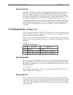
Analog input offset correction
The input to the A/D converter will be shorted to ground if bit 14 (MSB) is set to 1 while the inter-
nal channel selection of bits 8 through 10 specifies internal channels 4 through 7. (Bit 11 is not
used and therefore should be considered as “don’t care.”) This can be used for analog input offset
correction.
Control register (base + 2, write only)
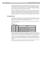
The control register specifies the pacer clock source and pre-scaler, the expansion mode, A/D
interrupt enable control, and part of the A/D trigger control. The bits are explained in Table C-9.
Clock source
The external clock source, if selected, must not exceed 5MHz with a minimum pulse width
greater than 100ns. The external clock frequency can be as low as DC, and there is no limit on the
maximum pulse width.
Expansion mode
Bit 5 has to be set to 1 if there is one (or more) expansion card(s) connected to the KPCMCIA-
12AIAOH PC card. This setting also indicates that all digital output lines (bits 0 to 3) will be used
for external channel selection and two of the four digital input lines (bits 1 and 3) will be used for
external gain selection.
A/D interrupt enable
Bits 3 and 4 are used for the A/D interrupt enable control. The EOS (end-of-scan) interrupt is
enabled (disabled) by setting bit 4 to 1 (0). Setting bit 3 to 1 (0) enables (disables) the data FIFO
interrupt when the A/D data FIFO becomes almost full. (Data available in the FIFO reaches the
almost-full threshold.) Since the EOS and FIFO threshold events are latched into the status reg-
ister, temporarily disabling the interrupt and then enabling it will not lose an interrupt as long as
no events are repeated during the time the interrupt is disabled.
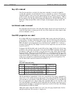
Table C-9
Control register bit definitions
Bit
Function
Explanation
7-6
Pacer clock source and
pre-scaler
00 : External clock
01 : Internal, 5MHz
10 : Internal, 1MHz
11 : Internal, 100kHz
5
Expansion mode
0/1 : disable/enable
4
EOS interrupt
0/1 : disable/enable
3
FIFO interrupt
0/1 : disable/enable
2
Trigger mode
0/1 : one-shot/continuous
1
Trigger source
0/1 : internal/external
0
Trigger edge
0/1 : rising/falling
Содержание KPCMCIA-12AIAOH
Страница 11: ...1 Introduction...
Страница 15: ...2 Installation...
Страница 17: ...3 Theory of Operation...
Страница 25: ...4 I O Connections...
Страница 28: ...5 Optional Accessories...
Страница 30: ...A Specifications...
Страница 33: ...B PCMCIA Interface...
Страница 36: ...C I O Registers...


