KPCMCIA-12AIAOH User’s Manual
PCMCIA Interface
B-3
Configuration and option register (COR)
Refer to Table B-2. Bits 6 and 7 of the configuration option register are defined by the PCMCIA
standard as the SRESET and the LevlREQ Bits. A 1 written into the SRESET bit puts the card
into a reset state, while a 0 moves it out of the reset state. When the card is in a reset state, it
behaves as if a hardware reset is received from the host. The LevlREQ bit controls the type of
interrupt signal generated by the PC card. Setting the configuration index bits to 0 makes the PC
card a memory-only card (accessed only by memory read/write operations), while setting it to 1
enables the card to be a standard I/O card.
Card configuration and status register (CCSR)
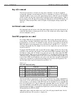
Refer to Table B-3. The KPCMCIA-12AIAOH PC card uses two bits in this register. When bit 1
is set to 1, it indicates a pending interrupt. The bit will remain as 1 until the software clears the
interrupt source. Bit 2 is used for power-down control. A 1 set to this bit puts the card into power-
down mode, while a 0 brings it back to full-powered mode. The rest of the bits are not used.
Table B-2
COR bit definitions
Bit
Name
Description
7
SRESET
1 = Put the card into a reset state
0 = Get out of a reset state
6
LevlReq
1 = Level mode interrupt
0 = Edge mode interrupt
5-0
Index bits
000000 = Memory mode
000001 = I/O mode
Table B-3
CCSR bit definitions
Bit
Name
Description
7-3
Not used
Reserved, all 0 when writing and reading
2
PwrDwn
1 = Power-down mode
0 = Full-powered mode
1
Intr
1 = Interrupt pending
0 = No interrupt pending
0
Reserved
Reserved as 0
Содержание KPCMCIA-12AIAOH
Страница 11: ...1 Introduction...
Страница 15: ...2 Installation...
Страница 17: ...3 Theory of Operation...
Страница 25: ...4 I O Connections...
Страница 28: ...5 Optional Accessories...
Страница 30: ...A Specifications...
Страница 33: ...B PCMCIA Interface...
Страница 36: ...C I O Registers...


