background image

Section 8: TSP command reference 

Model DMM7510 7½ Digit Graphical Sampling Multimeter Reference Manual 


8-264 

DMM7510-901-01 Rev. B / May 2015 


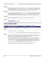
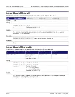
trigger.digout[N].logic 

This attribute sets the output logic of the trigger event generator to positive or negative for the specified line. 

Type 

TSP-Link accessible 

Affected by 

Where saved 

Default value 

Attribute (RW) 

Yes 

Restore configuration 
Instrument reset 
Power cycle 
Digital I/O trigger 

N

 reset 

Configuration script 

trigger.LOGIC_NEGATIVE 

Usage 

logicType

 = trigger.digout[

N

].logic 

trigger.digout[

N

].logic = 

logicType


logicType


The output logic of the trigger generator: 


Assert a TTL-high pulse for output: 

trigger.LOGIC_POSITIVE


Assert a TTL-low pulse for output: 

trigger.LOGIC_NEGATIVE


N


Digital I/O trigger line (1 to 6) 


Details 

This attribute controls the logic that the output trigger generator uses on the given trigger line. 

The output state of the digital I/O line is controlled by the trigger logic, and the user-specified output 
state of the line is ignored. 


Example 


digio.line[4].mode = digio.MODE_TRIGGER_OUT 

trigger.digout[4].logic = trigger.LOGIC_NEGATIVE 

Sets line 4 mode to be a trigger output 
and sets the output logic of the trigger 
event generator to negative (asserts a 
low pulse). 

Also see 

digio.line[N].mode

 (on page 8-52) 

digio.line[N].reset()

 (on page 8-54) 

Digital I/O port configuration

 (on page 3-49) 


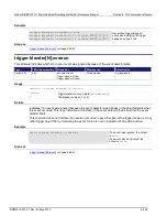
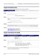
trigger.digout[N].pulsewidth 

This attribute describes the length of time that the trigger line is asserted for output triggers. 

Type 

TSP-Link accessible 

Affected by 

Where saved 

Default value 

Attribute (RW) 

Yes 

Restore configuration 
Instrument reset 
Power cycle 
Digital I/O trigger 

N

 reset 

Configuration script 

10e-6 (10 

µ

s) 

Usage 

width

 = trigger.digout[

N

].pulsewidth 

trigger.digout[

N

].pulsewidth = 

width


width


The pulse width (0 to 100 ks) 

N


Digital I/O trigger line (1 to 6) 


Содержание DMM7510

Страница 1: ...Reference Manual DMM7510 901 01 Rev B May 2015 PDMM751090101B DMM7510 901 01B www keithley com Model DMM7510 7 Digit Graphical Sampling Multimeter A Greater Measure of Confidence...

Страница 2: ...are trademarks of Keithley Instruments All Keithley Instruments product names are trademarks or registered trademarks of Keithley Instruments Other brand names are trademarks or registered trademarks...

Страница 3: ......

Страница 4: ...be connected to mains These instruments will be marked as category II or higher Unless explicitly allowed in the specifications operating manual and instrument labels do not connect any instrument to...

Страница 5: ...y disposed of according to federal state and local laws The WARNING heading in the user documentation explains dangers that might result in personal injury or death Always read the associated informat...

Страница 6: ...12 Home screen 2 12 Menu overview 2 22 Trigger menu 2 45 Scripts menu 2 47 System menu 2 49 Examples in this manual 2 55 Display features 2 55 Setting the number of displayed digits 2 55 Setting the...

Страница 7: ...Display results of two measure functions 2 133 Displayed measurements 2 134 Using Quick Setups 2 135 Auto Delay 2 137 Voltage autodelay and autorange times 2 138 Current autodelay and autorange times...

Страница 8: ...3 12 Setting up the averaging filter 3 12 Reading buffers 3 13 Getting started with buffers 3 13 Remote buffer operation 3 30 Saving front panel settings into a macro script 3 35 Recording a macro scr...

Страница 9: ...testing and binning 3 102 Limit testing using the front panel interface 3 102 TSP Link System Expansion Interface 3 104 TSP Link connections 3 105 TSP Link nodes 3 106 Master and subordinates 3 107 In...

Страница 10: ...em 6 15 ACAL COUNt 6 15 ACAL LASTrun TEMPerature INTernal 6 16 ACAL LASTrun TEMPerature DIFFerence 6 17 ACAL LASTrun TIME 6 18 ACAL NEXTrun TIME 6 19 ACAL REVert 6 19 ACAL RUN 6 20 ACAL SCHedule 6 21...

Страница 11: ...HIGH 6 65 SENSe 1 function ATRigger WINDow LEVel LOW 6 66 SENSe 1 function AVERage COUNt 6 67 SENSe 1 function AVERage STATe 6 68 SENSe 1 function AVERage TCONtrol 6 69 SENSe 1 function AVERage WINDo...

Страница 12: ...6 120 SENSe 1 COUNt 6 121 SENSe 1 DIGitize COUNt 6 122 SENSe 1 DIGitize FUNCtion ON 6 123 SENSe 1 FUNCtion ON 6 124 SENSe 1 TRIGger DIGitize STIMulus 6 125 SENSe 1 TRIGger MEASure STIMulus 6 127 STAT...

Страница 13: ...6 180 TRIGger BLOCk BRANch ALWays 6 181 TRIGger BLOCk BRANch COUNter 6 182 TRIGger BLOCk BRANch COUNter COUNt 6 183 TRIGger BLOCk BRANch COUNter RESet 6 183 TRIGger BLOCk BRANch DELTa 6 184 TRIGger B...

Страница 14: ...LEar 6 234 TRIGger TIMer n COUNt 6 235 TRIGger TIMer n DELay 6 237 TRIGger TIMer n STARt FRACtional 6 237 TRIGger TIMer n STARt GENerate 6 238 TRIGger TIMer n STARt OVERrun 6 239 TRIGger TIMer n STARt...

Страница 15: ...8 8 acal lastrun tempdiff 8 9 acal lastrun time 8 10 acal nextrun time 8 11 acal revert 8 12 acal run 8 12 acal schedule 8 13 beeper beep 8 14 buffer clearstats 8 15 buffer delete 8 16 buffer getstats...

Страница 16: ...9 dmm digitize analogtrigger window direction 8 80 dmm digitize analogtrigger window levelhigh 8 81 dmm digitize analogtrigger window levellow 8 82 dmm digitize aperture 8 83 dmm digitize count 8 84 d...

Страница 17: ...dmm measure configlist size 8 143 dmm measure configlist store 8 143 dmm measure count 8 145 dmm measure dbreference 8 146 dmm measure detectorbandwidth 8 147 dmm measure displaydigits 8 148 dmm meas...

Страница 18: ...g clear 8 204 eventlog getcount 8 204 eventlog next 8 205 eventlog post 8 206 eventlog save 8 207 exit 8 208 fan level 8 208 file close 8 209 file flush 8 210 file mkdir 8 210 file open 8 211 file rea...

Страница 19: ...nder N stimulus M 8 256 trigger blender N wait 8 258 trigger clear 8 259 trigger digin N clear 8 260 trigger digin N edge 8 260 trigger digin N overrun 8 261 trigger digin N wait 8 262 trigger digout...

Страница 20: ...CK_DELAY_CONSTANT 8 315 trigger model setblock trigger BLOCK_DELAY_DYNAMIC 8 316 trigger model setblock trigger BLOCK_DIGITAL_IO 8 317 trigger model setblock trigger BLOCK_DIGITIZE 8 318 trigger model...

Страница 21: ...s FAQs 9 1 I see a command that is not in the manual What is it 9 1 How do I display the instrument s serial number 9 2 What VISA resource name is required 9 2 Can I use Agilent GPIB cards with Keithl...

Страница 22: ...t images or contrast irregularities 3 Upgrading the firmware 4 From the front panel 5 Using TSP 5 Using SCPI 6 Using TSB 6 Common commands 1 Introduction 1 CLS 2 ESE 2 ESR 4 IDN 5 LANG 5 OPC 6 RST 7 S...

Страница 23: ...Table of Contents Model DMM7510 7 Digit Graphical Sampling Multimeter Reference Manual SRQ when reading buffer becomes full 16 Index 1...

Страница 24: ...nd the speed necessary for a broad range of applications from system applications and production testing to benchtop applications The Model DMM7510 meets application requirements for production engine...

Страница 25: ...http www keithley com Organization of manual sections The information in this manual is organized into the following major categories General operation Describes the components of the instrument and...

Страница 26: ...uilt in comparator for pass fail testing Digital I O for stand alone binning operations or interface to a component handler SCPI and Test Script Processor TSP TM programming languages with remote inte...

Страница 27: ...Section 1 Introduction Model DMM7510 7 Digit Graphical Sampling Multimeter Reference Manual 1 4 DMM7510 901 01 Rev B May 2015...

Страница 28: ...istogram 2 148 Automatic reference measurements 2 149 Saving setups 2 150 Using the event log 2 154 Resets 2 155 Instrument power Follow the steps below to connect the Model DMM7510 to line power and...

Страница 29: ...quately rated cords Failure to use properly rated cords may result in personal injury or death due to electric shock Connect the power cord To connect the power cord 1 Make sure that the front panel P...

Страница 30: ...e off position O HOME key Returns the display to the Home screen MENU key Opens the main menu Press the icons on the main menu to open measure view trigger script and system screens For details refer...

Страница 31: ...en the cursor is in a value entry field increases or decreases the value in the field Pressing the navigation control Selects the highlighted choice or allows you to edit the selected field ENTER key...

Страница 32: ...for details SENSE terminals Use the SENSE HI and SENSE LO terminals and the INPUT terminals with the 4 wire resistance 3 wire and 4 wire RTD temperature and DC voltage ratio functions INPUT terminals...

Страница 33: ...connection with the INPUT LO terminal Use the SENSE HI and SENSE LO terminals and the INPUT terminals with the 4 wire resistance 3 wire and 4 wire RTD temperature and DC voltage ratio functions AMPS...

Страница 34: ...P IP and complies with IEEE Std 802 3 ethernet LAN See LAN communication USB port USB B connection for communication control and data transfer For details see USB communications on page 2 78 Digital I...

Страница 35: ...tweezers or screwdrivers or pointed objects such as pens or pencils to touch the touchscreen It is strongly recommended that you use only fingers to operate the instrument Use of clean room gloves to...

Страница 36: ...nd options from the keypad or keyboard You can move the cursor in the entry box by touching the screen The cursor is moved to the spot in the entry box where you touched the screen On number keypads y...

Страница 37: ...the longer the screen is bright the shorter the screen life To adjust the backlight brightness from the front panel 1 Press the MENU key 2 Under System select Settings 3 Select the button next to Back...

Страница 38: ...display STATE_LCD_100 75 brightness display STATE_LCD_75 50 brightness display STATE_LCD_50 25 brightness display STATE_LCD_25 Display off display STATE_LCD_OFF Display key lights and all indicators...

Страница 39: ...at the top of the Home screen contain information about instrument settings and states Some of the indicators also provide access to instrument settings Press an indicator to get more information abo...

Страница 40: ...ment is communicating through Telnet TSP Link Instrument is communicating through TSP Link Slave Instrument is a subordinate in a TSP Link system Communications activity indicator The activity indicat...

Страница 41: ...ator menu Active script indicator This indicator shows script activity and allows you to control script action from the Home screen If there is no script activity the indicator displays No Script You...

Страница 42: ...trigger measurement method Figure 11 Trigger mode indicator Indicator Meaning CONT Continuous measurement The instrument is making measurements continuously MAN Manual trigger mode Press the front pan...

Страница 43: ...t Log see Using the event log on page 2 154 Figure 12 Error and message indicator The following table describes the different icons and what they mean Icon Description An empty triangle means that the...

Страница 44: ...they mean are defined in the following table Indicator Meaning 10M Input impedance is set to 10 M ACCPL AC signal coupling is enabled AUTO Input impedance is set to automatic AZERO Instrument automat...

Страница 45: ...Figure 14 Model DMM7510 swipe screens maximized and minimized Screen element Description 1 Minimize indicator You can swipe down to minimize the swipe screens 2 Swipe screen indicator Each circle rep...

Страница 46: ...ess to some instrument settings It shows you the present settings and allows you to change enable or disable them quickly The available settings depend on which measure function is active Figure 16 SE...

Страница 47: ...MENU key and selecting Graph under Views For more information about graphing measurements see Graphing on page 2 141 STATISTICS swipe screen The STATISTICS swipe screen contains information about the...

Страница 48: ...ogram the Model DMM7510 to show that a test is in process For details about using remote commands to program the display refer to Customizing a message for the USER swipe screen on page 2 58 Figure 19...

Страница 49: ...he measure function for the secondary measurement Swap Primary Switches the primary and secondary functions Depending on the selected functions a relay may click when the instrument switches between t...

Страница 50: ...Adjusts the balance between resolution and speed of the instrument Refer to Using the Performance slider on page 2 135 Quick Setups Sets up specific measure tests by following a few prompts Refer to U...

Страница 51: ...e 2 55 Input Impedance Sets impedance to Auto or 10 M Refer to DC voltage input impedance on page 2 98 Unit Allows voltage to be measured in volts or decibels Refer to Show voltage readings in decibel...

Страница 52: ...f displayed digits on page 2 55 Detector Bandwidth Sets the detector bandwidth Refer to Detector bandwidth on page 2 140 Integration Rate Controls the amount of time the input signal is measured apert...

Страница 53: ...crease common mode and normal mode noise rejection Refer to Line cycle synchronization on page 4 1 AC current measure settings The following options are available on the Measure Settings menu when the...

Страница 54: ...f digits that are displayed for front panel readings It does not affect accuracy or speed Refer to Setting the number of displayed digits on page 2 55 Offset Compensation Always set to off for 2 wire...

Страница 55: ...educes or eliminates thermoelectric EMFs in low level resistance measurements Refer to Offset compensated ohms on page 2 111 Open Lead Detect Enables or disables open lead detection When enabled detec...

Страница 56: ...lected Count Sets the number of aperture readings that are processed when a measurement is requested Line Sync Enables or disables line synchronization When it is enabled it helps increase common mode...

Страница 57: ...ured Refer to Ranges on page 3 3 Always set to 10 V for diode test Auto Delay Applies a wait period at the start of measurement to allow cables and circuitry to settle for best accuracy Refer to Auto...

Страница 58: ...ty and accuracy See Automatic reference measurements on page 2 149 Count Sets the number of aperture readings that are processed when a measurement is requested Line Sync Enables or disables line sync...

Страница 59: ...tor of the ratio The range also affects the accuracy of the measurements and the maximum signal that can be measured Refer to Ranges on page 3 3 Auto Delay Applies a wait period at the start of measur...

Страница 60: ...ested Unit Sets the units of measurement that are displayed on the front panel of the instrument and stored in the reading buffer AC Coupling Filter Available when Signal Coupling is set to AC Sets th...

Страница 61: ...he stack with a new measurement Select the repeating average filter to average a set of measurements and then flush the data out of the stack before averaging a new set of measurements Filter Count Th...

Страница 62: ...he test Limit State enables or disables a limit test for the selected measurement function When testing is enabled limit testing occurs on each measurement Limit testing compares the measurements to t...

Страница 63: ...s a list of available configuration lists from which you can choose New List Creates a new empty configuration list To populate the list with the present instrument settings select System to Index Del...

Страница 64: ...component of a DCV ratio measurement Capacity Sets the maximum number of readings that the buffer can store Note that when you resize a buffer the readings contained in that buffer are cleared Fill M...

Страница 65: ...two fingers on the screen and moving them together or apart in a pinching motion You can also move the view of the graph to the left or right by placing a finger on the screen and moving it in either...

Страница 66: ...ive buffer Add Trace Selects a reading buffer that is used to supply the data for a trace on the Graph tab You can select up to four reading buffers and specify the data type for the y axis for each T...

Страница 67: ...e color as the trace Y Axis Method The scale method determines how data is scaled on the Graph tab If you are graphing one trace you can select SmartScale The instrument scales the graph automatically...

Страница 68: ...Model DMM7510 7 Digit Graphical Sampling Multimeter Reference Manual Section 2 General operation DMM7510 901 01 Rev B May 2015 2 41...

Страница 69: ...ts will be cleared Never Any previously detected triggers are acted on immediately and not cleared Edge When the source is set to Digital TSP Link or External this sets the type of edge that generates...

Страница 70: ...ignal enters or leaves the defined upper and lower analog signal level boundaries Views Histogram menu The Histogram menu allows you to graph the distribution of measurement data in the selected readi...

Страница 71: ...artScale Automatically select the most appropriate scaling method Auto Bin Redistribute the data evenly in the bins based on the present minimum and maximum boundaries Fit Adjust the y axis scale so t...

Страница 72: ...trigger model that loads a configuration list At each configuration list index a measurement is made The list is iterated until every index in the configuration list has been loaded LogicTrigger Creat...

Страница 73: ...reen To see the parameters that you can change from the front panel select a block in the trigger model diagram The available options change depending on the type of block you select From this screen...

Страница 74: ...vailable scripts that you can select All scripts that are saved on the Model DMM7510 or are on a USB flash drive inserted into the instrument are listed Run Selected Runs the selected script immediate...

Страница 75: ...GE SCRIPTS menu Scripts Create Setup menu The Create Setup menu allows you to save the present settings and configuration lists of the instrument into a configuration script You can use this script to...

Страница 76: ...e event log communications backlight time and password settings The following topics describe the settings that are available on these interactive screens System Event Log menu The Event Log menu allo...

Страница 77: ...error messages error and warning messages or no messages in popups Messages continue to be saved in the event log when popups are turned off Log Warning Turns the logging of warnings on or off If thi...

Страница 78: ...you can set the IP address To change the address select the button next to IP Address and enter a new address Gateway Displays the present gateway address When TCP IP Mode is set to Manual you can se...

Страница 79: ...adjusts the brightness level Time and Date Sets the instrument month day year and time Command Set Select the type of commands to use when controlling the instrument from a remote interface SCPI or T...

Страница 80: ...red to the temperature during the last auto calibration The instrument updates the temperature when autozero references are refreshed If autozero is set to off the internal temperature is not updated...

Страница 81: ...ument Upgrade to New This option initiates a firmware upgrade from a file on a USB flash drive Downgrade to Older This option returns the Model DMM7510 to a previous version of the firmware from a fil...

Страница 82: ...table VOLTage DC TEMPerature RESistance VOLTage DC RATio VOLTage AC CONTinuity FRESistance DIGitize VOLTage CURRent DC FREQuency VOLTage DIODe DIGitize CURRent CURRent AC PERiod VOLTage CAPacitance T...

Страница 83: ...effect the next time you make a measurement From a remote interface SCPI commands Refer to DISPlay function DIGits on page 6 43 TSP commands For measure functions refer to dmm measure displaydigits on...

Страница 84: ...ay format From the front panel Press the MENU key 1 Under System select Settings 2 Select the button next to Reading Format Select the reading format Prefix or Exponent This setting takes effect the n...

Страница 85: ...bottom line allows up to 32 characters The examples shown here switch the display to the USER swipe screen set the first line to read Test in process and the second line to display Do not disturb Usin...

Страница 86: ...enter information as shown in the example below Figure 29 Input number example For more information on creating the interactive prompts see the following command descriptions display input number on...

Страница 87: ...weighs 4 08 kg 9 0 lb with the bumpers and handle and 3 63 kg 8 0 lb without them The following figure shows the mounting screw locations and dimensions Mounting screws must be 6 32 with a maximum scr...

Страница 88: ...2 General operation DMM7510 901 01 Rev B May 2015 2 61 Figure 32 Model DMM7510 dimensions side and top with handle and bumpers The following figures show the dimensions when the handle and bumpers ha...

Страница 89: ...and rear bumpers for using the instrument on a benchtop The handle rotates so that you can swing it below the bottom surface of the instrument to tilt the instrument up for easier front panel viewing...

Страница 90: ...front bumper Remove all connections to the rear panel of the Model DMM7510 before removing the rear bumper 3 To remove the rear bumper repeat the procedure in step 2 To remove the handle assembly 1 Gr...

Страница 91: ...trument You may need to enter a password to change the interface depending on the access mode The Model DMM7510 automatically detects the type of communications interface LAN GPIB or USB when you conn...

Страница 92: ...so allows you to send triggers to multiple instruments simultaneously If you use a USB interface it is difficult to synchronize triggers that are sent to multiple instruments For applications that req...

Страница 93: ...mands and status model topology You can have up to 15 devices connected to a GPIB interface including the controller The maximum cable length is the lesser of either The number of devices multiplied b...

Страница 94: ...To allow many parallel connections to one instrument stack the connectors Each connector has two screws to ensure that connections remain secure The figure below shows a typical connection diagram for...

Страница 95: ...f it is unique in the system This address cannot conflict with an address that is assigned to another instrument or to the GPIB controller GPIB controllers are usually set to 0 or 21 To be safe do not...

Страница 96: ...panel IFC When the instrument detects an interface clear IFC event the instrument enters the talker and the listener idle state When the instrument is in this state the GPIB indicators on the front pa...

Страница 97: ...t systems that include web access This section provides an overview of LAN communications for the Model DMM7510 When you connect using a LAN you can use a web browser to access the internal web page o...

Страница 98: ...ed to allow the receive line input to be connected to the transmit line output on the network interfaces Figure 42 One to one connection with a crossover cable The Model DMM7510 supports Auto MDIX and...

Страница 99: ...umentation networks two network interface cards are required in the computer controller Though the two networks are independent stations on the corporate network can access the instruments and the ins...

Страница 100: ...ation Figure 45 Instrumentation connection to enterprise routers or servers Set up LAN communications on the instrument This section describes how to set up manual or automatic LAN communications on t...

Страница 101: ...he LAN using SCPI or TSP commands For details see the SCPI command SYSTem COMMunication LAN CONFigure on page 6 137 or the TSP command lan ipconfig on page 8 218 Set up manual LAN configuration If nec...

Страница 102: ...strument to establish a connection Install LXI Discovery Browser software on your computer You can use the LXI Discovery Browser to identify the IP addresses of LXI certified instruments Once identifi...

Страница 103: ...iple ethernet connections to the instrument can be opened only one can be used to control the instrument at a time The port numbers for the LAN protocols and dead socket termination are listed in the...

Страница 104: ...be terminated and closed when the connection to the dead socket termination port is closed Reset LAN settings You can reset the password and the LAN settings from the rear panel by inserting a straig...

Страница 105: ...ts refers to devices that implement the USBTMC or USBTMC USB488 protocol The full version of National Instruments NI VISA provides a utility to create a USB driver for any other kind of USB device tha...

Страница 106: ...serial number The serial number of the instrument the serial number is also on the rear panel INSTR Use the USBTMC protocol To determine these parameters you can run the Keithley Configuration Panel w...

Страница 107: ...ure 48 Select Communication Bus dialog box 4 Select USB 5 Click Next The Select Instrument Driver dialog box is displayed Figure 49 Select Instrument Driver dialog box 6 Select Auto detect Instrument...

Страница 108: ...he instrument 10 Click Finish 11 Click Cancel to close the Wizard 12 Save the configuration From the Keithley Configuration Panel select File Save Verify the instrument through the Keithley Communicat...

Страница 109: ...ace that you can use to control the instrument Download access to a csv file that contains reading buffer data Administrative options and LXI information The instrument web page resides in the firmwar...

Страница 110: ...page of the instrument provides information about the instrument It includes The instrument model number manufacturer serial number and firmware revision number The TCP Raw Socket number and Telnet Po...

Страница 111: ...IP address to connect to the instrument It also includes the ID button which you can use to identify the instrument See Identify the instrument on page 2 84 Change the IP configuration through the we...

Страница 112: ...tings which may take a few moments You may lose your connection with the web interface after clicking Submit This is normal and does not indicate an error or failure of the operation If this occurs fi...

Страница 113: ...use button down and swipe up or down To scroll right or left hold the left mouse button down and swipe left or right You can also click the dots on the bar above the swipe screens to move from screen...

Страница 114: ...nterface You can change the instrument password from the web interface The default user name and password is admin Note that you cannot change the user name it remains at admin even if the password ha...

Страница 115: ...he software installs the following components Microsoft NET Framework NI TM IVI Compliance Package NI VISA TM Run Time Engine Keithley SCPI based Instrument IVI C driver Keithley I O Layer To install...

Страница 116: ...lable include SCPI An instrument specific language built on the SCPI standard TSP A scripting programming language that contains instrument specific control commands that can be executed from a stand...

Страница 117: ...rence status are shown You can also schedule and run autocalibration from this screen For more information see System Calibration menu on page 2 53 and Auto calibration on page 3 44 To view the line f...

Страница 118: ...n date is not available with TSP commands You can also create user defined strings to store custom instrument specific information in the instrument such as department number asset number or manufactu...

Страница 119: ...erefore hazardous voltages more than 30 Vrms can appear on LO terminals This can occur when the instrument is operating in any mode To prevent hazardous voltage from appearing on the LO terminals conn...

Страница 120: ...rly connected to protective earth safety ground Make sure the test fixture provides proper protection Properly make interlock connections between the Model DMM7510 the test fixture and any other instr...

Страница 121: ...etter for rack applications with fewer changes Setting the instrument to use the front or rear terminals The selection to use the front or rear terminals must be made using the front panel switch Ther...

Страница 122: ...rent measurements from 1 nA to 10 A Warmup time After the Model DMM7510 is turned on it must be allowed to warm up for at least 1 hours to allow the internal temperature to stabilize If the instrument...

Страница 123: ...ct disconnect device For example remove the device s power cord or turn off the power switch 2 Attach the test leads to the circuit under test Use appropriate safety rated test leads for this applicat...

Страница 124: ...the front panel To make a DC voltage measurement using the front panel 1 Make the connections as shown in the previous figures 2 Press the FUNCTION key 3 Select DC Voltage 4 Press the TRIGGER key for...

Страница 125: ...G input impedance For the 100 V and 1000 V ranges a 10 M input divider is placed across the HI and LO input terminals When the input impedance is set to 10 M the 100 mV to 1000 V ranges have a 10 M i...

Страница 126: ...to dmm measure inputimpedance on page 8 156 For the digitize voltage function refer to dmm digitize inputimpedance on page 8 91 AC voltage measurements This section describes how you can set up AC vo...

Страница 127: ...t the instrument is set to Continuous Measurement The measurements start displaying on the front panel Settings available for AC voltage measurements See AC voltage measure settings on page 2 25 for s...

Страница 128: ...pling Multimeter Reference Manual Section 2 General operation DMM7510 901 01 Rev B May 2015 2 101 Figure 61 Rear panel connections DC current measurement 3 A or less Figure 62 Rear panel connections D...

Страница 129: ...he front panel When the TERMINALS switch is set to REAR and autorange is enabled autoranging is limited to ranges up to 3 A ranges The 10 A range is not included in the autorange algorithm Settings av...

Страница 130: ...front panel To make an AC current measurement using the front panel 1 Make the connections as shown in the previous figures 2 Press the FUNCTION key 3 Select AC Current 4 Press the TRIGGER key for 2 s...

Страница 131: ...r high resistance measurements in a high humidity environment use Teflon TM insulated cables to minimize errors due to cable leakage Two wire compared to four wire measurements You can use 2 wire or 4...

Страница 132: ...esistance sensing for high impedance DUT Minimizing the effect of lead resistance with 4 wire testing The 4 wire sensing method shown in the following figure minimizes or eliminates the effects of lea...

Страница 133: ...Overflow If the signal is more than 10 mV the current pulse is automatically shut off and the 4 wire measurement continues For the 10 M to 1 G ranges only the Sense LO terminal is pulsed with a negati...

Страница 134: ...sense connections provides the most accurate low resistance measurement accuracy Specified accuracies for instrument measurement capabilities are only guaranteed when you use 4 wire remote sensing Fo...

Страница 135: ...raphical Sampling Multimeter Reference Manual 2 108 DMM7510 901 01 Rev B May 2015 Figure 71 Model DMM7510 front panel 4 wire remote sense connections 2 wire resistance measure connections Figure 72 Fr...

Страница 136: ...el 1 Make the connections as shown in the previous figures 2 Press the FUNCTION key 3 Select 2W Res 4 If the measurement method is set to continuous the measurements start displaying on the front pane...

Страница 137: ...using the front panel To make a 4 wire resistance measurement using the front panel 1 Make the connections as shown in the previous figures 2 Press the FUNCTION key 3 Select 4W Res 4 Press the TRIGGER...

Страница 138: ...t ohms for ranges up to 10 k maximum resistance of 2 4 k for the four wire resistance function You can use offset compensated ohms used with dry circuit ohms to cancel the effect of thermoelectric EMF...

Страница 139: ...LO and measured across the Sense HI and Sense LO terminals The second measurement is measured across Sense HI and Sense LO with an Ion test current from HI and LO The difference between the Ion and Io...

Страница 140: ...are selecting a manual range use the lowest possible range for the best resolution As with other measure settings the states of dry circuit ohms and offset compensated ohms are saved with four wire oh...

Страница 141: ...ing the front panel To make a continuity measurement using the front panel 1 Make the connections as shown in the previous figures 2 Press the FUNCTION key 3 Select Continuity 4 Press the TRIGGER key...

Страница 142: ...are wave inputs The input signal must be more than 10 of the AC voltage range If the input is less than 20 mV and measured on the 100 mV range the frequency must be more than 10 Hz For sine wave input...

Страница 143: ...TRIGGER key for 2 seconds and verify that the instrument is set to Continuous Measurement The measurements start displaying on the front panel Settings available for frequency measurements See Freque...

Страница 144: ...d using the front panel To make a period measurement using the front panel 1 Make the connections as shown in the previous figures 2 Press the FUNCTION key 3 Select Period 4 Press the TRIGGER key for...

Страница 145: ...00 A or 1 mA The diode function Itest current is very stable but it is 5 actual For simple I V semiconductor applications you can determine the actual Itest source value by using a remote command to r...

Страница 146: ...diode measurement using the front panel 1 Make the connections as shown in the previous figures 2 Press the FUNCTION key 3 Select Diode 4 Press the TRIGGER key for 2 seconds and verify that the instru...

Страница 147: ...B May 2015 Temperature measurements This section describes how to set up temperature measurements You can measure temperature using thermocouples thermistors and 3 wire or 4 wire resistance temperatur...

Страница 148: ...the Model DMM7510 The Model DMM7510 supports 3 wire and 4 wire RTD types of PT100 D100 F100 PT385 PT3916 You can also select the user type When the user type is selected you can define the alpha beta...

Страница 149: ...d discharged to approximately 0 V In the charge phase the Itest is sourced while measuring the voltage If the voltage on the DUT exceeds 2 8 V 10 the Itest is halted and the voltage is held until the...

Страница 150: ...rement using the front panel 1 Make the connections as shown in the previous figures 2 Press the FUNCTION key 3 Select Capacitance 4 Press the TRIGGER key for 2 seconds and verify that the instrument...

Страница 151: ...as SENSE HI and LO must be referenced to INPUT LO SENSE HI must not exceed 125 referenced to INPUT LO of the selected sense range To access the extra value in the reading buffer the reading buffer st...

Страница 152: ...approximately 3 00000 If Vsense is set to the 1 V range the ratio displays overflow with SENSE HI and SENSE LO terminals exceeding the 125 maximum reference to the LO terminals The SENSE HI to LO is 3...

Страница 153: ...measurement using the front panel 1 Make the connections as shown in the previous figures 2 Press the FUNCTION key 3 Select DCV Ratio 4 Press the TRIGGER key for 2 seconds and verify that the instrume...

Страница 154: ...he nearest integer The instrument will automatically adjust the aperture setting if the sample rate is changed to a rate that does not support the existing aperture setting When this occurs a warning...

Страница 155: ...MM7510 901 01 Rev B May 2015 Digitize voltage measure connections The connections for front panel and rear panel digitize voltage measurements are shown in the following graphics Figure 92 Front panel...

Страница 156: ...options refer to Digitize Voltage measure settings on page 2 33 8 Press the TRIGGER key for 2 seconds and verify that the instrument is set to Continuous Measurement The measurements display on the fr...

Страница 157: ...el To make a digitize current measurement using the front panel 1 Make the connections as shown in the previous figures 2 Press the FUNCTION key 3 Select the Digitize Functions tab 4 Select Digitize C...

Страница 158: ...iscrete 1 s averaged reading Although the maximum sample rate is 1 million samples per second the input filtering of the A D is set at a 3 dB corner point of slightly greater than 350 kHz to prevent a...

Страница 159: ...kHz bandwidth AC coupling is terminated with an RC filter that can be set to fast or slow Internally R is fixed at 1 1 M across the HI and LO terminals This optimizes bandwidth and measure loading Wh...

Страница 160: ...re displayed on the front panel and stored in the reading buffers To access the dual measurement capability swipe the lower half of the Home screen to the SECONDARY swipe screen This feature is only a...

Страница 161: ...r to DMM measurement overview on page 2 94 for connection information 2 Swipe to the SECONDARY swipe screen 3 Set up the primary function as needed 4 Select Second Function to select the secondary fun...

Страница 162: ...n and vice versa When the temperature function is selected the readings per second are shown as a range to accommodate the various transducer types Making a measurement with the QuickSet functions To...

Страница 163: ...sted The signal amplitude allows the instrument to select a fixed range that is large enough to measure your signal When the settings are complete the Graph screen is displayed with the measure result...

Страница 164: ...m the switch system indicates that the switch is ready and the instrument can make measurements Auto Delay Auto Delay applies a wait period at the end of a function change range change and other measu...

Страница 165: ...s 2 65 s 7 5 s 7 5 s 10 s 300 Hz Autodelay 50 ms 50 ms 50 ms 50 ms 250 ms Autorange 3 5 ms 3 5 s 850 ms 850 ms 2 5 s Current autodelay and autorange times The following tables provide times for autode...

Страница 166: ...todelay 3 ms 13 ms Autorange 2 5 ms 125 ms Frequency and period autodelay and autorange times The following table provides times for autodelay and autorange for the Model DMM7510 DMM frequency and per...

Страница 167: ...lect 3 Hz 30 Hz or 300 Hz When you select the 3 Hz bandwidth the signal goes through an analog root mean square RMS converter The output of the RMS converter goes to a fast 1 kHz sampling A D and the...

Страница 168: ...4 To add an additional buffer select Add Trace and select the reading buffer to add The Buffer Element dialog box is displayed 5 Select the buffer element to plot on they y axis for the trace you are...

Страница 169: ...e start of the group is indicated by a small triangle A group is automatically created when the measure or digitize count is set to more than 1 All All data in the buffer is displayed on the graph Off...

Страница 170: ...ger settings Readings are placed in the active reading buffer If a trigger model exists it is replaced by the new settings When you set up the Trigger tab settings are not applied if you press the EXI...

Страница 171: ...ings until 100 percent of the buffer is filled 8 Set the Trigger Clear behavior Select Enter to clear previously detected trigger events when entering the wait block select Never to immediately act on...

Страница 172: ...the options for the Edge waveform 1 Set the Level to the signal level that generates the trigger event 2 Set the Slope to rising or falling Rising causes a trigger event when the analog signal trends...

Страница 173: ...o a scale where the data point is visible and touch the data point The Data Point dialog box is displayed with the X and Y values of that point If you have the measure count set to more than 1 the gra...

Страница 174: ...trace Figure 102 Graph tab Buffers Stats swipe The Cursor swipe allows you to set no vertical horizontal or both cursors When cursors are displayed the Cursor swipe displays the values of each cursor...

Страница 175: ...he Histogram To set up the Histogram 1 Press the MENU key 2 In the View menu select Histogram 3 Select the Data tab 4 Select the Bin Buffer This reading buffer contains the data that is binned 5 Selec...

Страница 176: ...eing used for measurements The Model DMM7510 uses separate reference and zero measurements for each aperture By default the instrument automatically checks the reference measurements whenever a signal...

Страница 177: ...isplay To set autozero using SCPI commands Refer to the following commands SENSe 1 function AZERo STATe on page 6 72 SENSe 1 AZERo ONCE on page 6 114 To set autozero using TSP commands Refer to the fo...

Страница 178: ...to save To save the setup send the command createconfigscript setupName Where setupName is the name of the setup script that will be created Save a user setup to a USB flash drive From the front pane...

Страница 179: ...cripts select the name of the script 4 Select Delete A confirmation message is displayed 5 Select OK To delete a user setup from internal memory using SCPI commands You must overwrite an existing setu...

Страница 180: ...em settings to the script and displays a confirmation message Click OK 6 Press the EXIT key to return to the main menu 7 Under Scripts select Run The RUN SCRIPTS window opens 8 Select the script you j...

Страница 181: ...al error or warning The description of the event To access an event log listing from the front panel 1 Press the MENU key 2 Under System select Event Log 3 Select the System Events tab A list of event...

Страница 182: ...urn off the display of error popups Errors and Warnings Turn off the display of error and warning popups None Turn off the display of all popups Reset Popups Restores the popups setting to show errors...

Страница 183: ...using the TSP command set Resets some of the trigger blender settings to their factory defaults Refer to trigger blender N reset on page 8 256 Trigger timer reset This reset is only available if you...

Страница 184: ...cess You can set one of the following levels of access to the instrument Full Allows full access for all users from all interfaces Exclusive Allows access by one remote interface at a time with logins...

Страница 185: ...e button next to Access Mode 4 Select the level of password access control you want to enable Using SCPI commands Send the command that is appropriate for the level of access you want to enable SYSTem...

Страница 186: ...t range determines the full scale value of the measurement range for the selected measure function The range also affects the accuracy of the measurements and the maximum signal that can be measured Y...

Страница 187: ...a measurement The relative offset feature subtracts a set value or a baseline reading from measurement readings When you enable relative offset all measurements are recorded as the difference between...

Страница 188: ...ent by Using the front panel 1 Press the FUNCTION key and select the measure function 2 Press the MENU key 3 Select Calculations 4 For Rel select Acquire The relative offset value is displayed to the...

Страница 189: ...1 function RELative on page 6 92 and SENSe 1 function RELative STATe on page 6 96 TSP commands Refer to dmm measure rel level on page 8 181 and dmm measure rel enable on page 8 180 Using SCPI commands...

Страница 190: ...cause to be displayed in the Y axis Clear the reading buffer to remove the mixed units mx b The mx b math operation lets you manipulate normal display readings x mathematically according to the follow...

Страница 191: ...active the unit of measure for the front panel readings is and the MATH indicator is displayed to the right of the measurement You cannot change the unit designator Reciprocal 1 X You can set math ope...

Страница 192: ...ent on page 6 36 TSP commands Refer to dmm measure math format on page 8 168 and dmm measure math percent on page 8 171 Setting mx b math operations From the front panel 1 Press the FUNCTION key and s...

Страница 193: ...cal math format applied Over a remote interface SCPI commands Refer to CALCulate 1 function MATH FORMat on page 6 31 TSP commands Refer to dmm measure math format on page 8 168 Switching math on the S...

Страница 194: ...he tenth measurement is made the display or remote interface updates and returns the average of the 10 readings For additional information about the order in which math filters offsets and limits are...

Страница 195: ...1 Press the MENU key 2 Under Measure select Calculations 3 For Filter select On to enable filtering 4 Select Config 5 For the Filter Type select Moving or Repeat 6 For the Filter Count enter the numbe...

Страница 196: ...fers You cannot delete defbuffer1 and defbuffer2 Clear reading buffers Clear the default reading buffers and delete the user defined reading buffers by turning the instrument off or sending an instrum...

Страница 197: ...e buffer indicator on page 2 14 in the annunciator bar displays buffer fill status and the STATISTICS swipe screen on page 2 20 displays buffer statistics Figure 105 STATISTICS swipe screen The instru...

Страница 198: ...of the timestamp For the compact buffer style the timestamp is a 1 s accuracy relative timestamp with a one hour time span before the timestamp starts over For Standard and Full buffer styles the time...

Страница 199: ...e Style dialog box is displayed You can select Standard Store readings with full accuracy with formatting maximum 11 000 000 readings Compact Store readings with reduced accuracy 6 5 digits with no fo...

Страница 200: ...a reading buffer To create a full reading buffer named testData with a capacity of 200 readings send the following command TRACe MAKE testData 200 FULL Using TSP commands to create a reading buffer T...

Страница 201: ...dings are made and event code 4915 Attempting to store past capacity of reading buffer is displayed If a buffer that is set to fill once is partially filled and a new reading count is set that exceeds...

Страница 202: ...indow 3 Select a reading buffer from the list For example select testData The settings for testData are displayed Select the Capacity button and enter the new size for the buffer 4 Select OK The MANAG...

Страница 203: ...ent of a DCV ratio measurement Writable Manually write external data to a reading buffer For more information see Writable reading buffers on page 3 34 You cannot select this buffer style from the fro...

Страница 204: ...buffer to Fill once The buffer stops accepting data once it fills to capacity When the buffer reaches capacity no more readings are made and event code 4915 Attempting to store past capacity of readi...

Страница 205: ...testData are displayed 4 Select the Fill Mode option 5 Press the HOME key to return to the Home screen Using SCPI commands to set the buffer fill mode To set the testData reading buffer fill mode to...

Страница 206: ...the buffer is set to fill once and a return of 1 indicates the buffer is set to fill continuously Selecting a buffer The default reading buffer is defbuffer1 You can also use a different buffer defbuf...

Страница 207: ...D bufferName command is to send the command TRACe TRIGger bufferName The TRACe TRIGger command stores readings in the specified reading buffer If no buffer is specified for the parameter defbuffer1 is...

Страница 208: ...r To measure DC current store the readings in defbuffer1 and print the last reading in the buffer send the commands dmm measure func dmm FUNC_DC_CURRENT print dmm measure read Using the front panel to...

Страница 209: ...file that is already on the USB flash drive When you append data you can specify the starting and ending point in the buffer to save only a portion of the data and time format as you do when you save...

Страница 210: ...ame of the file you want to save It is not necessary to enter the file extension All files are saved as csv files 7 Press OK on the keyboard 8 Select Yes to confirm saving the file When the MANAGE REA...

Страница 211: ...myData csv on a USB flash drive send the following command buffer save defbuffer1 usb1 myData csv To save readings from a reading buffer named testData to a file named myData csv on a USB flash drive...

Страница 212: ...content on page 3 26 for details You cannot delete the default buffers defbuffer1 or defbuffer2 However the data in the default buffers is lost when the instrument is reset or the power is turned off...

Страница 213: ...number of readings a buffer can store This allows you to change the number of readings the buffer can store See TRACe POINts on page 6 162 TRACe WRITe FORMat For use with writable buffers only this fu...

Страница 214: ...This attribute reads the number of readings a buffer can store This allows you to change the number of readings the buffer can store See bufferVar capacity on page 8 22 buffer write format For use wi...

Страница 215: ...array notation If rb is a reading buffer the first measurement is accessed as rb 1 the ninth measurement as rb 9 and so on The additional information in the table is accessed as additional members of...

Страница 216: ...ded to the buffer See TRACe STATistics AVERage on page 6 166 TRACe STATistics MAXimum This command returns the maximum reading value added to the buffer See TRACe STATistics MAXimum on page 6 168 TRAC...

Страница 217: ...the printbuffer command This loop shows the same information described in the previous example reading units and relative timestamps for all readings stored in the buffer However because the print co...

Страница 218: ...you can view the data on your computer from the Model DMM7510 Virtual Front Panel or on the front panel graph screen Using graphing through the virtual front panel requires significant system resource...

Страница 219: ...n also stop or cancel recording from the Home screen Select the Recording indicator in the indicator bar After you create a macro script you can use the other Scripts menu options to run and manage sc...

Страница 220: ...the instrument is operating using its active settings For example if you set the measure NPLC to 1 0 the active NPLC setting is 1 0 Active state At any given time the complete set of active settings...

Страница 221: ...it the instrument stores the active settings to configuration index 1 Each time you store another set of active settings to the same list the instrument creates a new configuration index and appends...

Страница 222: ...he front panel see Using the front panel for configuration list operations on page 3 39 or by using remote commands see Using remote commands for configuration list operations on page 3 43 Using the f...

Страница 223: ...r to Measure Config Lists menu on page 2 36 Duplicate configuration indexes If you store a second configuration index that has the same settings as an index that is already on the configuration list N...

Страница 224: ...is displayed 3 Choose Select List A menu of available configuration lists is displayed 4 Select MyMeasList 5 Select System to Index This saves the active system settings to the configuration index The...

Страница 225: ...se Select List A menu of available configuration lists is displayed 3 Select MyMeasList The configuration indexes in the list display 4 Select the second configuration index 5 Select Index to System V...

Страница 226: ...n page 6 118 dmm measure configlist recall on page 8 142 View the contents of a configuration list index as TSP commands SENSe 1 CONFiguration LIST QUERy on page 6 117 dmm measure configlist query on...

Страница 227: ...been cycled You can run auto calibration with input cables connected At the start of the auto calibration process the front terminals are monitored If more than 30 V DC or 1 V AC is detected on the f...

Страница 228: ...that are active on the instrument are complete When the scheduled time occurs the autocalibration run command is placed in the command queue and will be executed after any previously sent commands or...

Страница 229: ...erval 6 Select Scheduled Time to select the time when the auto calibration will run or when you will be prompted to run it To review the next schedule time and date see the information listed next to...

Страница 230: ...temperature send print localnode internaltemp For the temperature difference send print acal lastrun tempdiff For the temperature when auto calibration was last run send print acal lastrun internalte...

Страница 231: ...male DB 9 connector The port provides a connection point to each of the six digital I O lines and other connections as shown in the following table Figure 120 Model DMM7510 digital I O port Model DMM...

Страница 232: ...ly 5 V write a 1 to it to set a line low nominally 0 V write a 0 to it To allow an external device to control the state of the line the line must be set to input mode or open drain mode An attached de...

Страница 233: ...uit for a relay You can externally power a different device by replacing the relay coil with the other device The relay is actuated by configuring the corresponding digital output line Most of these t...

Страница 234: ...igital I O In this mode the line can serve as an input an output or both You can read from the line or write to it When a digital I O line is used as an input in open drain mode you must write a 1 to...

Страница 235: ...igger line It is recommended that you reset the line before selecting and configuring this mode To use the line only as a trigger input 1 Reset the line 2 Set the input trigger edge detection type to...

Страница 236: ...igure the triggering master to synchronous master trigger mode or the non Keithley equivalent Configure all other instruments in the test system to the synchronous acceptor trigger mode or equivalent...

Страница 237: ...mulus event occurs Figure 124 Synchronous master output trigger Synchronous acceptor Use the synchronous acceptor trigger mode with the synchronous master mode or its non Keithley equivalent Only one...

Страница 238: ...The physical line state does not change until all drives internal and external release the line Action overruns occur if the internal drive is not latched low and a source event is received Figure 126...

Страница 239: ...o writeport on page 8 56 TRIGger DIGital n IN CLEar on page 6 204 This command clears the trigger event on a digital input line trigger digin N clear on page 8 260 TRIGger DIGital n IN EDGE on page 6...

Страница 240: ...ples These examples provide typical methods you can use to work with the digital I O port Outputting a bit pattern The programming examples below illustrate how to output the bit pattern 110101 at the...

Страница 241: ...can write binary decimal or hexadecimal values as shown below Use binary value digio writeport 0b110101 Use decimal value digio writeport 53 Use hexadecimal value digio writeport 0x35 Reading a bit pa...

Страница 242: ...ar panel of the instrument is a TTL compatible input output line with a 0 to 5 V logic signal You can use this line for triggering by using the transition of the line state to initiate an action The i...

Страница 243: ...h pulse or a TTL low pulse for the trigger You can use the external I O with interactive triggering or with the trigger model For more information about the trigger modes and triggering refer to Trigg...

Страница 244: ...ut on the external in line trigger extin edge on page 8 269 TRIGger EXTernal IN OVERrun on page 6 210 This command returns the event detector overrun status trigger extin overrun on page 8 269 Not ava...

Страница 245: ...reading buffer See Reading buffers on page 3 13 for detail on the buffer options that are available If you press the front panel TRIGGER key when the instrument is set to the continuous measurement m...

Страница 246: ...ighlighted 2 Select the method you want to use 3 If the instrument is in remote control the instrument displays a confirmation dialog box Select Yes to change to local control Triggering Triggering al...

Страница 247: ...onfigured and controlled similarly See Digital I O TSP Link System Expansion Interface on page 3 104 and External I O on page 3 59 for more information about connections and configuration and control...

Страница 248: ...cur when two complementary signal edges cross the trigger level and meet the polarity and timing constraints that you specify When you set up pulse mode you define the level width condition and polari...

Страница 249: ...u can enable high frequency rejection for any analog trigger mode False triggering around the set analog trigger level may occur with low frequency signals that are noisy DC or have low amplitude and...

Страница 250: ...or each trigger condition The buffer size is set to 100 000 readings The analog trigger is set to edge with a rising slope and level of 0 5 V High frequency rejection is disabled to allow triggering o...

Страница 251: ...alog trigger mode to edge with a rising slope and level of 0 5 V dmm digitize analogtrigger mode dmm MODE_EDGE dmm digitize analogtrigger edge slope dmm SLOPE_RISING dmm digitize analogtrigger edge le...

Страница 252: ...ware value indicates the state of the signal The instrument interprets changes in the hardware value of consecutive LXI trigger packets as edge transitions Edge transitions generate trigger events If...

Страница 253: ...eed to enable the trigger timers before using the SCPI TRIGger TIMer n STATe or the TSP trigger timer N enable command Count The count sets the number of events to generate each time the timer generat...

Страница 254: ...te command When this is set to on a trigger event is generated immediately when the timer is triggered When it is set to off a trigger event is generated when the timer elapses You can also watch for...

Страница 255: ...that takes a variable amount of time To ensure a precise time between measurements you can create a trigger timer and define it to be a fixed interval that is longer than the longest possible measurem...

Страница 256: ...der to wait for up to four input trigger events to occur before responding with an output event The Model DMM7510 has 1 or 2 event blenders that you can program Event blender operations You can use ev...

Страница 257: ...model you can use interactive triggering to enable your system to generate and detect trigger events anywhere in the test flow Interactive triggering is typically used in the context of TSP script op...

Страница 258: ...Setting the pulse width to 0 results in an indefinite length pulse when the assert function is used to output an external trigger When an indefinite length pulse is used the release function must be u...

Страница 259: ...so set up your own trigger models Trigger model blocks Each trigger model consists of blocks that can be combined to create the trigger model The blocks can be combined from the front panel or by send...

Страница 260: ...ng options are available Setting Description Event 1 An event that must occur before the trigger block will continue Event Logic Optional Determines if all of the defined events must occur or if at le...

Страница 261: ...ger Use the analog trigger LAN In Trigger A LXI trigger packet is received on LAN trigger object When you select this option you will also select the LAN trigger to monitor After you select the line p...

Страница 262: ...nt to infinite the trigger model executes subsequent blocks and digitizing continues in the background until the trigger model execution reaches another digitize block or until the trigger model ends...

Страница 263: ...tinue to be made Each measure and digitize function can have up to 5 unique user delay times M1 to M5 The delay time is set by the user delay command which is only available over a remote interface If...

Страница 264: ...ngs of the instrument based on the settings at that index The trigger model executes the settings at that index before the next block is executed The first time the trigger model encounters this block...

Страница 265: ...gh remote commands When you select the digital I O block the following options are available Setting Description Out Line Pattern Sets the value that specifies the output line bit pattern 0 to 63 Out...

Страница 266: ...assign this event to a command that takes an event For example if you want a notify block to trigger a digital I O line insert a notify block into the trigger model assign it a notify event and then c...

Страница 267: ...o create a bypass and skip the wait block the first time the trigger model runs This makes it possible to avoid deadlock when multiple instruments are being synchronized and each one is waiting for no...

Страница 268: ...A must be the low value and Limit B must be the high value Above The measurement is above the value set by limit B limit A must be set but is ignored when this type is selected Below The measurement...

Страница 269: ...asure or digitize block exists an error is reported When you select the Dynamic Limit block the following options are available Setting Description Limit Type How the limits are compared Inside The me...

Страница 270: ...o the target difference If the difference is less than the target difference the trigger model goes to the specified branching block If the difference is more than the target difference the trigger mo...

Страница 271: ...select the digital input to monitor After selecting the digital input line press Config to select the type of edge falling rising or either TSP Link Input Line edge detected on a TSP Link synchroniza...

Страница 272: ...01 01 Rev B May 2015 3 89 Always block When the trigger model reaches a branch always block it goes to the block that you specified When you select the always block the following option is available S...

Страница 273: ...l counter block TRIGger BLOCk BRANch COUNter RESet on page 6 183 trigger model setblock trigger BLOCK_RESET_BRANCH_COUNT on page 8 324 This creates a block in the trigger model that resets a branch co...

Страница 274: ...on page 8 312 This defines a trigger model block that clears the reading buffer TRIGger BLOCk CONFig NEXT on page 6 191 trigger model setblock trigger BLOCK_CONFIG_NEXT on page 8 313 This recalls the...

Страница 275: ...20 This allows you to log an event in the event log when the trigger model is running TRIGger BLOCk MEASure on page 6 199 trigger model setblock trigger BLOCK_MEASURE on page 8 321 This defines a trig...

Страница 276: ...of time LoopUntilEvent Creates a trigger model that makes continuous measurements until a specified event occurs GradeBinning Creates a trigger model that successively measures components and compare...

Страница 277: ...on the options available for each predefined trigger model trigger model load ConfigList trigger model load DurationLoop trigger model load Empty on page 8 289 trigger model load GradeBinning on page...

Страница 278: ...y stops the trigger model As the trigger model reaches each block the action defined by that block is started and completed before the trigger model moves to the next block Blocks do not overlap The t...

Страница 279: ...k LIST Using TSP commands To check the settings for a block send the command print trigger model getblocklist To retrieve the TSP code for trigger model blocks that were entered through the front pane...

Страница 280: ...interface is available immediately after the instrument executes the initiate command so that other commands can be executed while the trigger model is running To change the measurement method see Swi...

Страница 281: ...it is making measurements continuously MAN Not available through remote interface Not available through remote interface Instrument is not using trigger model makes measurements when you press the fr...

Страница 282: ...fy trigger blocks Branch on event trigger blocks Command interface triggers Digital I O lines TSP Link synchronization lines LAN triggers Analog triggers External I O triggers Event blenders which com...

Страница 283: ...BLENder n Trigger timer n 1 to 4 expired TIMer n Analog trigger ATRigger External in trigger EXTernal Trigger events TSP command set Trigger events Event description Event constant No trigger event tr...

Страница 284: ...ey events Respond to an event with a wait block The wait building block causes the trigger model to stop and wait for an event or set of events to occur before continuing You can specify up to three e...

Страница 285: ...ttern to physically place the tested device in a bin If multiple tests are performed on the same part determine when the part should be binned Bin the part as soon as it fails a test Bin the part afte...

Страница 286: ...ct HOME to return to the operating display 10 Make a measurement L1PASS is displayed if the measurement is in the limits L1FAIL is displayed if the measurement is not in the limits An example of using...

Страница 287: ...k is a high speed trigger synchronization and communication bus that test system builders can use to connect multiple instruments in a master and subordinate configuration Once connected all the instr...

Страница 288: ...nes that are built into the TSP Link connection If you are using a TSP Link network you do not have to modify any connections Example connections for a TSP Link system are shown in the following figur...

Страница 289: ...Each node must be identified with a unique node number This identification is called a TSP Link node number An individual node is accessed as node N where N is the node number assigned to the node Yo...

Страница 290: ...script from the front panel of any instrument node connected to the system When a script is run all nodes in the system go into remote operation When the script is finished running all the nodes in th...

Страница 291: ...nstruments in the system is turned off The actual number of nodes is less than the expected number From the front panel 1 Power on all instruments connected to the TSP Link network 2 Press the MENU ke...

Страница 292: ...You can terminate a script that is executing on a TSP Link system To terminate an executing script and return all nodes to local control send the following command abort This dissolves the master sub...

Страница 293: ...nnected to the master node A group can consist of one or more nodes You must assign group numbers to each node using remote commands If you do not assign a node to a group it defaults to group 0 which...

Страница 294: ...der The last node in a group that performs any operation initiated by the master node is the group leader The group leader Performs operations initiated by the master node Initiates remote operations...

Страница 295: ...that group errors will occur You can execute the waitcomplete command on the master node or group leader to wait for overlapped operations The action of waitcomplete depends on the parameters specifi...

Страница 296: ...addition the master node and the group leaders can use the data queue as a way to coordinate activities Tables in the data queue consume one entry When a node stores a table in the data queue a copy...

Страница 297: ...ers trigger tsplinkout N release on page 8 343 Releases a latched trigger on the given TSP Link trigger line trigger tsplinkout N stimulus on page 8 344 Specifies the event that causes the synchroniza...

Страница 298: ...nt data The output would be similar to 7 To read bit B1 only To read bit B1 only data tsplink line 1 state print data The output would be similar to tsplink STATE_HIGH Using Model DMM7510 TSP Link com...

Страница 299: ...with a device that is that is not TSP enabled without the use of a controlling computer Using TSP Net library methods you can transfer string data to and from a remote instrument transfer and format...

Страница 300: ...tspnet connect ipAddress portNumber initString Where connectionID is the connection ID that will be used as a handle in all other tspnet function calls ipAddress is the IP address of the remote device...

Страница 301: ...s If the Model DMM7510 is connected to a TSP enabled instrument through TSP Net all events that occur on the remote instrument are transferred to the event log of the Model DMM7510 The Model DMM7510 i...

Страница 302: ...uter s tspnet read id n print string format from computer s tspnet read id n print string format from computer s tspnet read id n end function test_tspnet tspnet reset Connect to a computer using Teln...

Страница 303: ......

Страница 304: ...age current temperature continuity resistance and DC voltage ratio You can enable line synchronization for NPLC measurements which increases the normal mode rejection ratio NMRR and common mode reject...

Страница 305: ...ts The longest amount of time or highest NPLC value provides the lowest reading noise and more usable digits but has the slowest reading rate The Model DMM7510 has a nonlinear shape for its speed vers...

Страница 306: ...ue for the other For example if you set an aperture of 0 035 then set an NPLC value of 2 the aperture value is changed to 0 033333333 To set NPLC using the front panel 1 Press the FUNCTION key 2 Selec...

Страница 307: ...measured voltage Simple schematics of the 2 wire and 4 wire constant current methods are shown below The test current sourced to the DUT depends on the selected measurement range For example for the...

Страница 308: ...is method is generated by a 6 9 V voltage source through a 10 M reference resistance RREF as shown in the figure below Basic circuit theory dictates that IREF is equal to the IDUT Because the voltmete...

Страница 309: ...an also be used to measure ohms for the 10 M and 100 M ranges To minimize the effects of charge injection when autozero is enabled the 10 M to 100 M is actually a 3 wire ohm measurement SENSE HI is no...

Страница 310: ...otentials are generated when different parts of the circuit are at different temperatures and when conductors made of dissimilar metals are joined together Thermoelectric EMFs can cause the following...

Страница 311: ...l B V C T1 is the temperature of the B junction C or K T2 is the temperature of the A junction C or K A typical test setup has several copper to copper junctions Each junction can have a thermoelectri...

Страница 312: ...still have residual thermoelectric offsets after following the guidelines in Minimizing thermoelectric EMFs on page 4 8 If the offsets are relatively constant you can use the relative offset feature...

Страница 313: ...ignal In some situations the Model DMM7510 digital filter may help to reduce RFI effects In some cases additional external filtering may also be required However filtering may have detrimental effects...

Страница 314: ...values shown on the front panel Cable effects on dry circuit ohms Dry circuit resistance applications include measurements where the voltage applied across the device under test DUT is limited to 20 m...

Страница 315: ...t is in place there is test current flowing through the cable that connects the HI and LO of the DMM to the DUT When the short is removed the energy stored in this cable can force a voltage across the...

Страница 316: ...del DMM7510 7 Digit Graphical Sampling Multimeter Reference Manual Section 4 Measure considerations DMM7510 901 01 Rev B May 2015 4 13 Figure 142 Voltage oscillation Figure 143 Voltage between HI and...

Страница 317: ...esponse With offset compensation enabled and reading triggering halted the idle test current of all dry circuit ranges is less than or equal to 10 A When the Model DMM7510 is in either of these setups...

Страница 318: ...rement process and reading calculation eliminates the resistance contributed by the presence of VEMF When the source is turned on the output cycles between the programmed value and zero 0 A or 0 V to...

Страница 319: ...Reference Manual 4 16 DMM7510 901 01 Rev B May 2015 For more information on these operations see the following topics Filtering measurement data on page 3 11 Relative offset on page 3 4 Calculations t...

Страница 320: ...xecuted Valid commands that follow an invalid command in a command message are ignored Command messages A command message is made up of one or more command words sent by the controller to the instrume...

Страница 321: ...d RST SENSe CURRent REL STAT ON SENSe CURRent RELative 5 If commands are not combined the colon at the beginning of a command is optional For example the following commands are equivalent SENSe CURRen...

Страница 322: ...instrument case is not important you can mix uppercase and lowercase letters in program messages For example you can send the command SENSe COUNt in any of the following formats SENSe COUNt sense coun...

Страница 323: ...on send a device clear before sending the second query command When you query a Boolean option the instrument returns a 0 or 1 even if you sent OFF or ON when you originally sent the command SCPI para...

Страница 324: ...s that you can use to control your instrument Each command description is broken into several standard subsections The figure below shows an example of a command description Figure 146 SCPI command de...

Страница 325: ...ll the system settings this setting is changed to the saved value Instrument reset When you reset the instrument this command is reset to its default value Reset can be done from the front panel or wh...

Страница 326: ...ters Indicated by angle brackets Some commands have optional parameters Optional parameters are presented on separate lines in the Usage section presented in the required order with each valid permuta...

Страница 327: ...command description code examples 1 Example code that you can copy from this table and paste into your own application Examples are generally shown using the short forms of the commands 2 Description...

Страница 328: ...em 6 129 SYSTem subsystem 6 135 TRACe subsystem 6 151 TRIGger subsystem 6 177 FETCh This query command requests the latest reading from a reading buffer Type Affected by Where saved Default value Quer...

Страница 329: ...The options for bufferElements are described in the following table Option Description DATE The date when the data point was measured not available for reading buffers that are set to the style compa...

Страница 330: ...surements Bit hex Name Decimal Description 0x0001 STAT_QUESTIONABLE 1 Measure status questionable 0x0006 STAT_ORIGIN 6 A D converter from which reading originated for the Model DMM7510 this will alway...

Страница 331: ...LTage DC RESistance TEMPerature VOLTage DC RATio VOLTage AC FRESistance CONTinuity DIGitize VOLTage CURRent DC DIODe FREQuency VOLTage DIGitize CURRent CURRent AC CAPacitance PERiod VOLTage Details Th...

Страница 332: ...s for a data point The options for bufferElements are described in the following table Option Description DATE The date when the data point was measured not available for reading buffers that are set...

Страница 333: ...s Bit hex Name Decimal Description 0x0001 STAT_QUESTIONABLE 1 Measure status questionable 0x0006 STAT_ORIGIN 6 A D converter from which reading originated for the Model DMM7510 this will always be 0 M...

Страница 334: ...le Not applicable Not applicable Usage MEASure DIGitize MEASure DIGitize function MEASure DIGitize function bufferName MEASure DIGitize function bufferName bufferElements MEASure DIGitize bufferName M...

Страница 335: ...SENse DIGitize FUNCtion function then READ When specifying buffer elements you can Specify buffer elements in any order Include up to 12 elements in a single list You can repeat elements as long as t...

Страница 336: ...s be 0 Main or 2 digitizer 0x0008 STAT_TERMINAL 8 Measure terminal front is 1 rear is 0 0x0010 STAT_LIMIT2_LOW 16 Measure status limit 2 low 0x0020 STAT_LIMIT2_HIGH 32 Measure status limit 2 high 0x00...

Страница 337: ...ess than 12 Use a comma to delineate multiple elements for a data point The options for bufferElements are described in the following table Option Description DATE The date when the data point was mea...

Страница 338: ...the Model DMM7510 this will always be 0 Main or 2 digitizer 0x0008 STAT_TERMINAL 8 Measure terminal front is 1 rear is 0 0x0010 STAT_LIMIT2_LOW 16 Measure status limit 2 low 0x0020 STAT_LIMIT2_HIGH 3...

Страница 339: ...fer elements you can Specify buffer elements in any order Include up to 12 elements in a single list You can repeat elements as long as the number of elements in the list is less than 12 Use a comma t...

Страница 340: ...ng originated for the Model DMM7510 this will always be 0 Main or 2 digitizer 0x0008 STAT_TERMINAL 8 Measure terminal front is 1 rear is 0 0x0010 STAT_LIMIT2_LOW 16 Measure status limit 2 low 0x0020 S...

Страница 341: ...anel of the instrument these are stored as scripts named Setup0 n Example RCL 3 Restores the settings stored in memory location 3 Also see Saving setups on page 2 150 SAV on page 6 14 SAV This command...

Страница 342: ...ponents used in the DMM as a result of temperature and time ACAL COUNt This command returns the number of times automatic calibration has been run Type Affected by Where saved Default value Query only...

Страница 343: ...le Usage ACAL LASTrun TEMPerature INTernal Details The temperature is displayed in Celsius C The instrument updates the internal temperature value when the instrument refreshes autozero If autozero is...

Страница 344: ...IFFerence Details The temperature is displayed in Celsius C The instrument updates the internal temperature value when the instrument refreshes autozero If autozero is set to off or if autozero is not...

Страница 345: ...ved Default value Query only Not applicable Nonvolatile memory Not applicable Usage ACAL LASTrun TIME Details The date and time is returned in the format MM DD YYYY HH MM SS NNNNNNNNN Where MM DD YYYY...

Страница 346: ...NEXT TIME Returns date and time when the next auto calibration is scheduled to be run Example output 05 29 2014 17 11 17 000000000 Also see ACAL RUN on page 6 20 ACAL SCHedule on page 6 21 ACAL REVer...

Страница 347: ...calibration a progress message is displayed on the front panel At completion an event message is generated If you have set up auto calibration to run at a scheduled interval when you send the run comm...

Страница 348: ...tion does not start until all actions that are active on the instrument are complete When the scheduled time occurs the autocalibration run command is placed in the command queue and will be executed...

Страница 349: ...sables the beeper Type Affected by Where saved Default value Command and query Recall settings Instrument reset Power cycle Measure configuration list Save settings Measure configuration list Continui...

Страница 350: ...nd and query Recall settings Instrument reset Power cycle Measure configuration list Save settings Measure configuration list ON 1 Usage CALCulate2 function LIMit Y CLEar AUTO state CALCulate2 functio...

Страница 351: ...omatically cleared Also see CALCulate2 function LIMit Y CLEar IMMediate on page 6 24 CALCulate2 function LIMit Y CLEar IMMediate This command clears the results of the limit test defined by Y Type Aff...

Страница 352: ...ear off Enable the beeper for limit 1 when a voltage measurement exceeds the limit Set lower limit 1 for voltage to 0 25 V Set upper limit 1 for voltage to 2 5 V Enable limit 1 testing for voltage Mak...

Страница 353: ...selected measurement function The response message indicates if the limit test passed or how it failed on the high or low limit If autoclear is set to off reading the results of a limit test does not...

Страница 354: ...ge 6 23 CALCulate2 function LIMit Y CLEar IMMediate on page 6 24 CALCulate2 function LIMit Y STATe on page 6 29 Limit testing and binning on page 3 102 CALCulate2 function LIMit Y LOWer DATA This comm...

Страница 355: ...lue Default is 0 3 for limit 1 when the diode function is selected The default for limit 2 for the diode function is 1 Example CALC2 VOLT LIM1 CLE AUTO OFF CALC2 VOLT LIM1 AUD FAIL CALC2 VOLT LIM1 LOW...

Страница 356: ...function LIMit Y STATe function The function to which the setting applies see Functions Y Limit number 1 or 2 state Disable the limit test OFF or 0 Enable the limit test ON or 1 Functions VOLTage DC...

Страница 357: ...t Y CLEar IMMediate on page 6 24 CALCulate2 function LIMit Y FAIL on page 6 26 CALCulate2 function LIMit Y LOWer DATA on page 6 27 CALCulate2 function LIMit Y UPPer DATA on page 6 30 CALCulate2 functi...

Страница 358: ...VOLT LIMIT1 FAIL CALC2 VOLT LIM1 CLE Set limit autoclear off Enable the beeper for limit 1 when a voltage measurement exceeds the limit Set lower limit 1 for voltage to 0 25 V Set upper limit 1 for vo...

Страница 359: ...nce constant Reciprocal The reciprocal math operation displays measurement values as reciprocals The displayed value is 1 X where X is the measurement value if relative offset is being used this is th...

Страница 360: ...te 1 function MATH MBFactor MINimum CALCulate 1 function MATH MBFactor MAXimum function The function to which the setting applies see Functions n The offset for the y mx b operation the valid range is...

Страница 361: ...factor m for the y mx b math operation Type Affected by Where saved Default value Command and query Recall settings Instrument reset Power cycle Measure configuration list Save settings Measure config...

Страница 362: ...factor x is the measurement reading if you are using a relative offset this is the measurement with relative offset applied b is the user defined constant for the offset factor Example CALC VOLT MATH...

Страница 363: ...s see Functions n The reference used when the math operation is set to percent the range is 1e12 to 1e12 Functions VOLTage DC RESistance TEMPerature VOLTage DC RATio VOLTage AC FRESistance CONTinuity...

Страница 364: ...OFF or 0 Enable math operations ON or 1 Functions VOLTage DC RESistance TEMPerature VOLTage DC RATio VOLTage AC FRESistance CONTinuity DIGitize VOLTage CURRent DC DIODe FREQuency VOLTage DIGitize CURR...

Страница 365: ...al I O line 1 to 6 lineType Sets the digital line control type the options are Allow direct digital control of the line DIGital Configure for trigger control TRIGger Configure as a synchronous master...

Страница 366: ...e positive logic setting when you want to generate a rising edge trigger OPENdrain Configures the line to be an open drain signal This makes the line compatible with other instruments that use open dr...

Страница 367: ...gital input DIG LINE n MODE DIG IN you can query the state of the digital input line When a reset occurs the digital line state can be read as high because the digital line is reset to a digital input...

Страница 368: ...ificant bit bit B1 of the binary number corresponds to digital I O line 1 bit B6 corresponds to digital I O line 6 For example a returned value of 42 has a binary equivalent of 101010 which indicates...

Страница 369: ...an integer equivalent value The binary representation of the value indicates the output pattern to be written to the I O port For example a value of 63 has a binary equivalent of 111111 all lines are...

Страница 370: ...play Test running Also see DISPlay USER n TEXT DATA on page 6 47 DISPlay function DIGits This command determines the number of digits that are displayed for measurements on the front panel Type Affect...

Страница 371: ...hen return to the function for which you set display digits the display digits setting you set previously is retained The change in digits occurs the next time a measurement is made To change the numb...

Страница 372: ...ust the backlight brightness and dimmer on page 2 10 DISPlay READing FORMat This command determines the format that is used to display measurement readings on the front panel display of the instrument...

Страница 373: ...Home screen with large readings HOME_LARGe_reading Reading table READing_table Graph screen opens last selected tab GRAPh Histogram screen HISTogram FUNCTIONS swipe screen SWIPE_FUNCtions GRAPH swipe...

Страница 374: ...screen on which to display text Top line 1 Bottom line 2 textMessage String that contains the message up to 20 characters for USER1 and 32 characters for USER2 Details This command defines text messag...

Страница 375: ...cycle Save settings 0 Usage FORMat ASCii PRECision n FORMat ASCii PRECision DEFault FORMat ASCii PRECision MINimum FORMat ASCii PRECision MAXimum FORMat ASCii PRECision FORMat ASCii PRECision DEFault...

Страница 376: ...a is written The SWAPped byte order must be used when transmitting binary data to a computer with a Microsoft Windows operating system The ASCII data format can only be sent in the normal byte order I...

Страница 377: ...ed in the ASCII format The Model DMM7510 only responds to input commands using the ASCII format regardless of the data format that is selected for output strings The IEEE Std 754 binary formats use fo...

Страница 378: ...fected by Where saved Default value Query only Not applicable Not applicable Not applicable Usage ROUTe TERMinals Details You must use the front panel TERMINALS button to change which set of terminals...

Страница 379: ...nel settings into a macro script on page 3 35 SCRipt RUN This command runs a script Type Affected by Where saved Default value Command only Not applicable Not applicable Not applicable Usage SCRipt RU...

Страница 380: ...ved Default value Command and query Recall settings Instrument reset Power cycle Measure configuration list Save settings Measure configuration list See Details Usage SENSe 1 function APERture n SENSe...

Страница 381: ...asurement which is the integration period for the selected measurement function The integration period is specified in seconds In general a short integration period provides a fast reading rate while...

Страница 382: ...et to automatic or to a specific value in 1 s intervals The aperture is the actual acquisition time of the instrument on the signal It must be less than the set sample rate The minimum aperture is 1 s...

Страница 383: ...FRESistance CONTinuity DIGitize VOLTage CURRent DC DIODe FREQuency VOLTage DIGitize CURRent CURRent AC CAPacitance PERiod VOLTage Details This command is only available when the analog trigger mode i...

Страница 384: ...C RATio VOLTage AC FRESistance CONTinuity DIGitize VOLTage CURRent DC DIODe FREQuency VOLTage DIGitize CURRent CURRent AC CAPacitance PERiod VOLTage Details This is only available when the analog trig...

Страница 385: ...LTage AC FRESistance CONTinuity DIGitize VOLTage CURRent DC DIODe FREQuency VOLTage DIGitize CURRent CURRent AC CAPacitance PERiod VOLTage Details False triggering around the set analog trigger level...

Страница 386: ...e VOLTage DC RATio VOLTage AC FRESistance CONTinuity DIGitize VOLTage CURRent DC DIODe FREQuency VOLTage DIGitize CURRent CURRent AC CAPacitance PERiod VOLTage Details When edge is selected the analog...

Страница 387: ...tion function The function to which the setting applies see Functions setting The setting The pulse width must be greater than the specified pulse width GReater The pulse width must be less than the s...

Страница 388: ...ies see Functions value The signal level Functions VOLTage DC RESistance TEMPerature VOLTage DC RATio VOLTage AC FRESistance CONTinuity DIGitize VOLTage CURRent DC DIODe FREQuency VOLTage DIGitize CUR...

Страница 389: ...ing Above ABOVe Below BELow Functions VOLTage DC RESistance TEMPerature VOLTage DC RATio VOLTage AC FRESistance CONTinuity DIGitize VOLTage CURRent DC DIODe FREQuency VOLTage DIGitize CURRent CURRent...

Страница 390: ...OLTage CURRent DC DIODe FREQuency VOLTage DIGitize CURRent CURRent AC CAPacitance PERiod VOLTage Details This option is only available when the analog trigger mode is set to pulse This option sets eit...

Страница 391: ...ions VOLTage DC RESistance TEMPerature VOLTage DC RATio VOLTage AC FRESistance CONTinuity DIGitize VOLTage CURRent DC DIODe FREQuency VOLTage DIGitize CURRent CURRent AC CAPacitance PERiod VOLTage Det...

Страница 392: ...DIGitize VOLTage CURRent DC DIODe FREQuency VOLTage DIGitize CURRent CURRent AC CAPacitance PERiod VOLTage Details Only available when the analog trigger mode is set to window The high level must be g...

Страница 393: ...Quency VOLTage DIGitize CURRent CURRent AC CAPacitance PERiod VOLTage Details Only available when the analog trigger mode is set to window The low level must be less than the high level To use the ana...

Страница 394: ...imum function The function to which the setting applies see Functions n The number of readings required for each filtered measurement 1 to 100 Functions VOLTage DC RESistance TEMPerature VOLTage DC RA...

Страница 395: ...trument reset Power cycle Measure configuration list Save settings Measure configuration list OFF 0 Usage SENSe 1 function AVERage STATe state SENSe 1 function AVERage STATe function The function to w...

Страница 396: ...SENSe 1 function AVERage TCONtrol on page 6 69 SENSe 1 function AVERage WINDow on page 6 71 SENSe 1 function AVERage TCONtrol This command sets the type of averaging filter that is used for the select...

Страница 397: ...asurement is made it is copied into all the stack locations to fill the stack A true average is not produced until the stack is filled with new measurements The size of the stack is determined by the...

Страница 398: ...range Functions VOLTage DC RESistance TEMPerature VOLTage DC RATio VOLTage AC FRESistance CONTinuity DIGitize VOLTage CURRent DC DIODe FREQuency VOLTage DIGitize CURRent CURRent AC CAPacitance PERiod...

Страница 399: ...eadings the instrument must periodically get new measurements of its internal ground and voltage reference The time interval between updates to these reference measurements is determined by the integr...

Страница 400: ...al function The function to which the setting applies see Functions Functions VOLTage DC RESistance TEMPerature VOLTage DC RATio VOLTage AC FRESistance CONTinuity DIGitize VOLTage CURRent DC DIODe FRE...

Страница 401: ...on BIAS LEVel MINimum SENSe 1 function BIAS LEVel MAXimum SENSe 1 function BIAS LEVel SENSe 1 function BIAS LEVel DEFault SENSe 1 function BIAS LEVel MINimum SENSe 1 function BIAS LEVel MAXimum functi...

Страница 402: ...erature VOLTage DC RATio VOLTage AC FRESistance CONTinuity DIGitize VOLTage CURRent DC DIODe FREQuency VOLTage DIGitize CURRent CURRent AC CAPacitance PERiod VOLTage Details This command selects the t...

Страница 403: ...ty DIGitize VOLTage CURRent DC DIODe FREQuency VOLTage DIGitize CURRent CURRent AC CAPacitance PERiod VOLTage Details This option is only used when digitize signal coupling is set to AC When the signa...

Страница 404: ...function AC FREQuency function The function to which the setting applies see Functions range The frequency 3 Hz to 1 MHz Functions VOLTage DC RESistance TEMPerature VOLTage DC RATio VOLTage AC FRESist...

Страница 405: ...m SENSe 1 function DB REFerence SENSe 1 function DB REFerence DEFault SENSe 1 function DB REFerence MINimum SENSe 1 function DB REFerence MAXimum function The function to which the setting applies see...

Страница 406: ...able 0 or OFF available for all ranges Enable 1 or ON available for 1 to 10 k ranges Functions VOLTage DC RESistance TEMPerature VOLTage DC RATio VOLTage AC FRESistance CONTinuity DIGitize VOLTage CUR...

Страница 407: ...onfiguration list ON Usage SENSe 1 function DELay AUTO state SENSe 1 function DELay AUTO function The function to which the setting applies see Functions state Disable the auto delay OFF Enable the au...

Страница 408: ...ult SENSe 1 function DELay USER n MINimum SENSe 1 function DELay USER n MAXimum function The function to which the setting applies see Functions n The user delay to which this time applies 1 to 5 dela...

Страница 409: ...MAXimum function The function to which the setting applies see Functions n 3 Hz 30 Hz or 300 Hz Functions VOLTage DC RESistance TEMPerature VOLTage DC RATio VOLTage AC FRESistance CONTinuity DIGitize...

Страница 410: ...00 V and 1000 V ranges a 10 M input divider is placed across the HI and LO input terminals When the input impedance is set to 10 M the 100 mV to 1000 V ranges have a 10 M input divider across the HI a...

Страница 411: ...ction LINE SYNC state SENSe 1 function LINE SYNC function The function to which the setting applies see Functions state Disable OFF or 0 Enable ON or 1 Functions VOLTage DC RESistance TEMPerature VOLT...

Страница 412: ...TEMPerature VOLTage DC RATio VOLTage AC FRESistance CONTinuity DIGitize VOLTage CURRent DC DIODe FREQuency VOLTage DIGitize CURRent CURRent AC CAPacitance PERiod VOLTage Details This command sets the...

Страница 413: ...e 6 53 Using aperture or NPLCs to adjust speed and accuracy on page 4 1 SENSe 1 function OCOMpensated This command enables or disables offset compensation Type Affected by Where saved Default value Co...

Страница 414: ...offset compensation is enabled the measure range is limited to a maximum of 100 k Offset compensation is automatically enabled when dry circuit is enabled For 2 wire resistance measurements offset co...

Страница 415: ...LTage DC RATio VOLTage AC FRESistance CONTinuity DIGitize VOLTage CURRent DC DIODe FREQuency VOLTage DIGitize CURRent CURRent AC CAPacitance PERiod VOLTage Details For temperature measurements this is...

Страница 416: ...the input terminals of the instrument When auto range is enabled the range increases at 120 percent of range and decreases occurs when the reading is 10 percent of nominal range For example if you ar...

Страница 417: ...VOLTage CURRent DC DIODe FREQuency VOLTage DIGitize CURRent CURRent AC CAPacitance PERiod VOLTage Details You can assign any real number using this command The instrument selects the closest fixed ra...

Страница 418: ...A available for rear terminals 2 wire resistance 10 100 1 k 10 k 100 k 1 M 10 M 100 M 1 G 4 wire resistance 1 10 100 1 k 10 k 100 k 1 M 10 M 100 M 1 G Continuity 1 k fixed Diode 10 V fixed Capacitanc...

Страница 419: ...ction to which the setting applies see Functions n The relative offset value see Details Functions VOLTage DC RESistance TEMPerature VOLTage DC RATio VOLTage AC FRESistance CONTinuity DIGitize VOLTage...

Страница 420: ...tance 1e 09 1e 09 Diode 10 10 Capacitance 0 001 0 001 Temperature 3310 3310 Continuity 1000 1000 Frequency 1e 06 1e 06 Period 1 1 DC voltage ratio Method set to result 1E 12 1E 12 DC voltage ratio Met...

Страница 421: ...lative offset level When you send this command the instrument does not apply any math limit test or filter settings to the measurement even if they are set It is a measurement that is made as if these...

Страница 422: ...Gitize CURRent CURRent AC CAPacitance PERiod VOLTage Details This command determines if relative offset is applied to the voltage measurements before the ratio calculation or if the relative offset is...

Страница 423: ...r 1 Functions VOLTage DC RESistance TEMPerature VOLTage DC RATio VOLTage AC FRESistance CONTinuity DIGitize VOLTage CURRent DC DIODe FREQuency VOLTage DIGitize CURRent CURRent AC CAPacitance PERiod VO...

Страница 424: ...tion RTD ALPHa MAXimum function The function to which the setting applies see Functions n 0 to 0 01 Functions VOLTage DC RESistance TEMPerature VOLTage DC RATio VOLTage AC FRESistance CONTinuity DIGit...

Страница 425: ...h the setting applies see Functions value 0 to 1 Functions VOLTage DC RESistance TEMPerature VOLTage DC RATio VOLTage AC FRESistance CONTinuity DIGitize VOLTage CURRent DC DIODe FREQuency VOLTage DIGi...

Страница 426: ...nction The function to which the setting applies see Functions n 0 to 5 Functions VOLTage DC RESistance TEMPerature VOLTage DC RATio VOLTage AC FRESistance CONTinuity DIGitize VOLTage CURRent DC DIODe...

Страница 427: ...h the setting applies see Functions type The type of four wire RTD PT100 PT100 PT385 PT385 PT3916 PT3916 D100 D100 F100 F100 User specified type USER Functions VOLTage DC RESistance TEMPerature VOLTag...

Страница 428: ...plies see Functions type The type of three wire RTD PT100 PT100 PT385 PT385 PT3916 PT3916 D100 D100 F100 F100 User specified type USER Functions VOLTage DC RESistance TEMPerature VOLTage DC RATio VOLT...

Страница 429: ...Se 1 function RTD ZERO MAXimum function The function to which the setting applies see Functions n Range 0 to 10 000 Functions VOLTage DC RESistance TEMPerature VOLTage DC RATio VOLTage AC FRESistance...

Страница 430: ...es see Functions n 1 000 to 1 000 000 readings per second Functions VOLTage DC RESistance TEMPerature VOLTage DC RATio VOLTage AC FRESistance CONTinuity DIGitize VOLTage CURRent DC DIODe FREQuency VOL...

Страница 431: ...nually or automatically This command determines how the range is selected When this command is set to off you must set the range If you do not set the range the instrument remains at the range that wa...

Страница 432: ...DIGitize VOLTage CURRent DC DIODe FREQuency VOLTage DIGitize CURRent CURRent AC CAPacitance PERiod VOLTage Details Determines the full scale input for the reference measurement in the denominator of...

Страница 433: ...ulated DEFault SENSe 1 function TCouple RJUNction SIMulated MINimum SENSe 1 function TCouple RJUNction SIMulated MAXimum function The function to which the setting applies see Functions tempValue The...

Страница 434: ...ing applies see Functions identifier B E J K N R S or T Functions VOLTage DC RESistance TEMPerature VOLTage DC RATio VOLTage AC FRESistance CONTinuity DIGitize VOLTage CURRent DC DIODe FREQuency VOLTa...

Страница 435: ...ion to which the setting applies see Functions n The thermistor type in ohms 2252 2252 5000 5000 10000 10000 Functions VOLTage DC RESistance TEMPerature VOLTage DC RATio VOLTage AC FRESistance CONTinu...

Страница 436: ...ion to which the setting applies see Functions n The level 700 V to 700 V dependent on range Functions VOLTage DC RESistance TEMPerature VOLTage DC RATio VOLTage AC FRESistance CONTinuity DIGitize VOL...

Страница 437: ...INimum SENSe 1 function THReshold RANGe MAXimum function The function to which the setting applies see Functions n The range 0 1 to 700 instrument selects nearest valid range 100 mV 1 V 10 V 100 V 700...

Страница 438: ...C CAPacitance PERiod VOLTage Details This command determines how the range is selected When this command is set to off you must set the range If you do not set the range the instrument remains at the...

Страница 439: ...ce CONTinuity DIGitize VOLTage CURRent DC DIODe FREQuency VOLTage DIGitize CURRent CURRent AC CAPacitance PERiod VOLTage Details The transducer type determines the type of temperature measurement that...

Страница 440: ...T function The function to which the setting applies see Functions unitOfMeasure Temperature KELVin CELSius or FAHRenheit Digitize voltage AC voltage and DC voltage VOLT or DB Functions VOLTage DC RES...

Страница 441: ...CURRent CURRent AC CAPacitance PERiod VOLTage Details This command forces a refresh of the reference and zero measurements that are used for the present aperture setting for the selected function Whe...

Страница 442: ...n use this command to retrieve the names of measure configuration lists that are stored in the instrument This command returns one name each time you send it This command returns an empty string when...

Страница 443: ...guration lists are not saved when the instrument is turned off To save a configuration list use a saved setup to store the instrument settings which include defined configuration lists Example SENS CO...

Страница 444: ...This also means that if you want to delete all the indexes in a configuration list you must delete index 1 repeatedly until all indexes have been removed Example SENSe CONF LIST DELete myMeasList Dele...

Страница 445: ...on index in a measure configuration list Type Affected by Where saved Default value Command only Not applicable Not applicable Not applicable Usage SENSe 1 CONFiguration LIST RECall name SENSe 1 CONFi...

Страница 446: ...CONFiguration LIST CREate on page 6 116 SENSe 1 CONFiguration LIST STORe on page 6 120 SENSe 1 CONFiguration LIST SIZE This command returns the size number of configuration indexes of a measure config...

Страница 447: ...me of a measure configuration list index A number that defines a specific configuration index in the configuration list Details Use this command to store the active settings to a configuration index i...

Страница 448: ...io VOLTage AC FRESistance CONTinuity DIGitize VOLTage CURRent DC DIODe FREQuency VOLTage DIGitize CURRent CURRent AC CAPacitance PERiod VOLTage Details This command sets the number of measurements tha...

Страница 449: ...n page 6 231 SENSe 1 DIGitize COUNt This command sets the number of measurements to digitize when a measurement is requested Type Affected by Where saved Default value Command and query Recall setting...

Страница 450: ...A string that contains the measurement function to make active Current CURRent Voltage VOLTage Details Set this command to the type of measurement you want to digitize Reading this command returns th...

Страница 451: ...string that contains the measure function see Functions Functions VOLTage DC RESistance TEMPerature VOLTage DC RATio VOLTage AC FRESistance CONTinuity DIGitize VOLTage CURRent DC DIODe FREQuency VOLT...

Страница 452: ...ding It forces the instrument to make a digitize measurement the next time it detects the specified trigger event Options for the trigger event parameter are listed in the following table A digitize f...

Страница 453: ...r based on the configuration of the line detected on digital input line n 1 to 6 DIGio n Line edge detected on TSP Link synchronization line n 1 to 3 TSPLink n Appropriate LXI trigger packet is receiv...

Страница 454: ...It forces the instrument to make a measurement the next time it detects the specified trigger event Options for the trigger event parameter are listed in the following table A measure function must b...

Страница 455: ...r rising falling or either based on the configuration of the line detected on digital input line n 1 to 6 DIGio n Line edge detected on TSP Link synchronization line n 1 to 3 TSPLink n Appropriate LXI...

Страница 456: ...and Operation Event Register set It does not affect the Questionable Event Enable or Operation Event Enable registers Example STATus CLEar Clear the bits in the registers Also see CLS on page 2 STATus...

Страница 457: ...When sending hexadecimal values preface n with h No preface is needed when sending decimal values Example STAT OPER ENAB b0101000000000000 Sets the 12 and 14 bits of the operation status enable regist...

Страница 458: ...rs When you query the mapping for a specific bit the instrument returns the events that were mapped to set and clear that bit Zero 0 indicates that the bits have not been set Example STATus OPERation...

Страница 459: ...t queue The Standard Event Status Register is not affected by this command Example STAT PRES Resets the registers Also see Status model on page 1 STATus QUEStionable CONDition This command reads the Q...

Страница 460: ...limit test 3 failure value is exceeded Check to see that the value was set Also see None STATus QUEStionable MAP This command queries mapped event numbers or maps event numbers to bits in the event r...

Страница 461: ...bit 0 in the condition register is cleared Also see None STATus QUEStionable EVENt This command reads the Questionable Event Register Type Affected by Where saved Default value Query only Not applicab...

Страница 462: ...erfaces PROTected Allows access by one interface at a time including the front panel with passwords required on all interfaces LOCKout Details When access is set to full the instrument accepts command...

Страница 463: ...o 100 s Details You can use the beeper of the instrument to provide an audible signal at a specific frequency and time duration Using this function from a remote interface does not affect audible erro...

Страница 464: ...LAN settings are assigned If automatic configuration is selected the instrument automatically determines the LAN information When method is automatic the instrument first attempts to configure the LA...

Страница 465: ...value Query only Not applicable Not applicable Not applicable Usage SYSTem COMMunication LAN MACaddress Details The MAC address is a character string representing the MAC address of the instrument in...

Страница 466: ...mmand does not affect the event log that is displayed on the front panel If there are no entries in the event log the following message is returned 0 No error 0 0 0 This command returns only error mes...

Страница 467: ...see SYSTem EVENtlog NEXT Example SYST ERR CODE Returns the error code of the next error in the event log For example if error 222 Parameter data out of range error occurred the output is 222 Also see...

Страница 468: ...et to Returns the number of errors ERRor Returns the number of warnings WARNing Returns the number of informational messages INFormational Returns all events ALL Details A count finds the number of un...

Страница 469: ...vent log Once an event is read it can no longer be accessed remotely However it can be viewed on the front panel To read multiple commands execute this command multiple times If there are no entries i...

Страница 470: ...Usage SYSTem EVENtlog POST message SYSTem EVENtlog POST message eventType message A string that contains the message that will be associated with this event eventType The type of event that is genera...

Страница 471: ...the file to be saved eventType Limits the event log entries that are saved to specific types set to ERRor Saves only error entries WARNing Saves only warning entries INFormational Saves only informat...

Страница 472: ...se level of the instrument fan Quiet fan level speed control may increase internal temperature which could compromise performance to specifications When you set the fan level to quiet Audible noise de...

Страница 473: ...ddress takes effect when the command to change it is processed If there are response messages in the output queue when this command is processed they must be read at the new address If command message...

Страница 474: ...s the instrument password Type Affected by Where saved Default value Command only Rear panel LAN reset Nonvolatile memory admin Usage SYSTem PASSword NEW password password A string that contains the i...

Страница 475: ...hen you power on the instrument Power on to RST defaults RST Stored setup 0 SAV0 Stored setup 1 SAV1 Stored setup 2 SAV2 Stored setup 3 SAV3 Stored setup 4 SAV4 Details When you select RST the instrum...

Страница 476: ...e of the instrument in Celsius C The instrument checks internal temperature when it updates references when autozero is on Internal temperature is not checked if autozero is set to off It can also bec...

Страница 477: ...nute 0 to 59 second Second 0 to 59 Details When queried without a parameter this command returns the present timestamp value in seconds since January 1 1970 to the nearest second If you query with 1 t...

Страница 478: ...1996 0 Also see None TRACe subsystem The TRACe subsystem contains commands that control the reading buffers TRACe ACTual This command contains the number of readings in the specified reading buffer Ty...

Страница 479: ...tput 850 TRACe ACTual testData Returns the number of readings in the buffer testData Example output 10 Also see Reading buffers on page 3 13 Remote buffer operation on page 3 30 TRACe MAKE on page 6 1...

Страница 480: ...em in buffer test1 Get the start and end index of test1 Output 1 12 Also see Reading buffers on page 3 13 Remote buffer operation on page 3 30 TRACe ACTual STARt on page 6 153 TRACe MAKE on page 6 160...

Страница 481: ...licable Not applicable Usage TRACe CLEar TRACe CLEar bufferName bufferName A string that indicates the reading buffer the default buffers defbuffer1 or defbuffer2 or the name of a user defined buffer...

Страница 482: ...ified defbuffer1 is used bufferElements A list of elements in the buffer to print if nothing is specified READing is used see Details for the list of options for buffer elements a maximum of 14 comma...

Страница 483: ...information associated with the measurement see the Buffer status bits for sense measurements table below TIME The time when the data point was measured TSTamp The timestamp when the data point was me...

Страница 484: ...E 05 0 020199 5 047250E 05 0 040201 5 001598E 05 0 079671 5 053504E 05 0 099205 Read 5 data points and include relative time for each data point Output 0 0 020199 0 040201 0 079671 0 099205 Returns th...

Страница 485: ...buffer is specified defbuffer1 is used Details When a reading buffer is set to fill once no data is overwritten in the buffer When the buffer is filled no more data is stored in that buffer and new re...

Страница 486: ...TRACe LOG STATe bufferName logState Do not log information events OFF or 0 Log information events ON or 1 bufferName A string that indicates the reading buffer the default buffers defbuffer1 or defbuf...

Страница 487: ...FULLWRITable Details You cannot assign user defined reading buffers the name defbuffer1 or defbuffer2 If you create a reading buffer that has the same name as an existing user defined buffer an event...

Страница 488: ...the buffer named bufferVolts Make a new buffer named bufferVolts to store 1000 readings Query the size of bufferVolts again to verify it can store 1000 readings Output 1000 Example 3 TRACe POINts 5000...

Страница 489: ...r1 is used Details This command allows you to change or view how many readings a buffer can store Changing the size of a buffer will cause any existing data in the buffer to be lost The overall capaci...

Страница 490: ...efbuffer1 is used timeFormat Defines how date and time information from the buffer is saved in the file on the USB flash drive the values are Dates times and fractional seconds are saved the default v...

Страница 491: ...r each measurement request and return the data Make the measurements Read the reading and relative timestamp value for each point from 1 to 5 Output 0 000000 0 000000 0 000000 0 301759 0 000000 0 5790...

Страница 492: ...d buffer if no buffer is specified defbuffer1 is used timeFormat Indicates how date and time information from the buffer is saved in the file on the USB flash drive the values are Dates times and frac...

Страница 493: ...ons 6 through 10 testData to the myData5 csv file using raw timestamps Also see Reading buffers on page 3 13 Remote buffer operation on page 3 30 TRACe MAKE on page 6 160 TRACe STATistics AVERage This...

Страница 494: ...n associated with the specified buffer Type Affected by Where saved Default value Command only Not applicable Not applicable Not applicable Usage TRACe STATistics CLEar TRACe STATistics CLEar bufferNa...

Страница 495: ...ng that indicates the reading buffer the default buffers defbuffer1 or defbuffer2 or the name of a user defined buffer if no buffer is specified defbuffer1 is used Example TRACe STAT MAXimum Returns t...

Страница 496: ...ng that indicates the reading buffer the default buffers defbuffer1 or defbuffer2 or the name of a user defined buffer if no buffer is specified defbuffer1 is used Example TRACe STAT MINimum Returns t...

Страница 497: ...fault buffer defbuffer1 TRACe STAT PK2Pk testData Returns the peak to peak reading value in the user defined buffer testData Also see Reading buffers on page 3 13 Remote buffer operation on page 3 30...

Страница 498: ...pe Affected by Where saved Default value Command only Not applicable Not applicable Not applicable Usage TRACe TRIGger TRACe TRIGger bufferName bufferName A string that indicates the reading buffer th...

Страница 499: ...etails A digitize function must be selected before sending this command This command makes the number of digitize measurements that is set by the digitize count command Example DIG FUNC VOLTage TRACe...

Страница 500: ...buffer index AMP AMP_AC CELSius DECibel FAHRenheit FARad HERTz KELVin NONE OHM PERCent RATio RECiprocal SECond VOLT VOLT_AC WATT X displayDigits Integer from 3 to 8 extraUnits The units for the secon...

Страница 501: ...AC MAKE write2me 1000 FULLWRIT TRAC WRIT FORM write2me WATT 4 WATT 4 TRAC WRIT READ write2me 1 7 TRAC WRIT READ write2me 2 8 TRAC WRIT READ write2me 3 9 TRAC WRIT READ write2me 4 10 TRAC WRIT READ wri...

Страница 502: ...lue seconds fractionalSeconds TRACe WRITe READing bufferName readingValue extraValue seconds fractionalSeconds status bufferName A user supplied string that indicates the name of the buffer readingVal...

Страница 503: ...e2me 1000 FULLWRIT TRAC WRIT FORM write2me WATT 4 WATT 4 TRAC WRIT READ write2me 1 7 TRAC WRIT READ write2me 2 8 TRAC WRIT READ write2me 3 9 TRAC WRIT READ write2me 4 10 TRAC WRIT READ write2me 5 11 T...

Страница 504: ...ands on the instrument Type Affected by Where saved Default value Command only Not applicable Not applicable Not applicable Usage ABORt Details When this command is received the instrument stops the t...

Страница 505: ...umber 1 or 2 Details This command sets the blender event detector to the undetected state and resets the overrun indicator of the event detector Example TRIG BLEN2 CLE Clears the event detector for bl...

Страница 506: ...indicates whether or not an event was ignored because of the event detector state Type Affected by Where saved Default value Query only Not applicable Not applicable Not applicable Usage TRIGger BLEN...

Страница 507: ...be any of the trigger events shown in the following table Trigger events Event description Event constant No trigger event NONE Front panel TRIGGER key press DISPlay Notify trigger block n 1 to 8 the...

Страница 508: ...mand defines a trigger model block that always goes to a specific block Type Affected by Where saved Default value Command only Recall settings Instrument reset Power cycle Save settings Not applicabl...

Страница 509: ...of times Counters increment every time the trigger model reaches them until they are more than or equal to the count value At that point the trigger model continues to the next building block in the s...

Страница 510: ...AS 2 TRIG BLOC BRAN COUN 3 5 2 TRIG BLOC DEL CONS 4 1 TRIG BLOC BRAN COUN 5 3 2 INIT TRIG BLOCK BRAN COUN COUN Reset trigger model settings Clear defbuffer1 at the beginning of the trigger model Loop...

Страница 511: ...ELTa This command defines a trigger model block that goes to a specified block if the difference of two measurements meets preset criteria Type Affected by Where saved Default value Command only Recal...

Страница 512: ...TRIG BLOC BRAN DELT 5 0 5 7 4 Configure trigger block 5 to compare the differences between the measurements made in block 4 If the difference between them is less the 0 5 branch to block 7 Also see D...

Страница 513: ...ne edge either rising falling or either based on the configuration of the line detected on digital input line n 1 to 6 DIGio n Line edge detected on TSP Link synchronization line n 1 to 3 TSPLink n Ap...

Страница 514: ...limit that the measurement is compared against OUTside The low limit that the measurement is compared against limitB The upper limit that the measurement is tested against if limitType is set to ABOVe...

Страница 515: ...easure or digitize block If the measurements are outside of the 0 15 and 0 65 limits branch to block 8 Also see Constant Limit block on page 3 85 TRIGger BLOCk BRANch LIMit DYNamic This command define...

Страница 516: ...block must occur in the trigger model before the branch on dynamic limits block If no measure or digitize block is defined the measurement from the previous measure or digitize block is used If no pre...

Страница 517: ...the trigger model to go to a specified building block every time the trigger model encounters it except for the first time Type Affected by Where saved Default value Command only Recall settings Inst...

Страница 518: ...default buffer or a buffer that you defined If you are clearing a user defined reading buffer you must create the buffer before you define this block Example TRIG LOAD EMPTY TRIG BLOC BUFF CLE 1 TRIG...

Страница 519: ...the previous index in a configuration list Type Affected by Where saved Default value Command only Recall settings Instrument reset Power cycle Save settings Not applicable Usage TRIGger BLOCk CONFig...

Страница 520: ...ble Usage TRIGger BLOCk CONFig RECall blockNumber configurationList TRIGger BLOCk CONFig RECall blockNumber configurationList index blockNumber The sequence of the block in the trigger model configura...

Страница 521: ...tops normal measurement and trigger model operation for the amount of time set by the delay Background measurements continue to be made and if any previously executed block started infinite measuremen...

Страница 522: ...operation for the amount of time set by the delay Background measurements continue to be made Each measure and digitize function can have up to 5 unique user delay times M1 to M5 The delay time is set...

Страница 523: ...gital I O line 6 The bit mask defines the bits in the pattern that are driven high or low A binary 1 in the bit mask indicates that the corresponding I O line should be driven according to the bit pat...

Страница 524: ...the measurement to complete 3 The instrument places the measurement into the specified reading buffer which cannot be of the writable buffer style If you are defining a user defined reading buffer yo...

Страница 525: ...1 3 BRANCH_COUNTER VALUE 5 BRANCH_BLOCK 2 4 DELAY_CONSTANT DELAY 1 000000000 5 BRANCH_COUNTER VALUE 3 BRANCH_BLOCK 2 Also see None TRIGger BLOCk LOG EVENt This command allows you to log an event in t...

Страница 526: ...te Set trigger model block 9 to log an event when the trigger model completes Also see None TRIGger BLOCk MEASure This command defines a trigger block that makes a measurement Type Affected by Where s...

Страница 527: ...MEAS 2 defbuffer2 TRIG BLOC BRAN COUN 3 5 2 TRIG BLOC DEL CONS 4 1 TRIG BLOC BRAN COUN 5 3 2 Reset trigger model settings Clear defbuffer2 at the beginning of the trigger model Set the measurements to...

Страница 528: ...odel execution reaches a notify block the instrument generates a trigger event and immediately continues to the next block Other commands can reference the event that the notify block generates This a...

Страница 529: ...ogic If each event must occur before the trigger model continues AND If at least one of the events must occur before the trigger model continues OR Details You can use the wait block to synchronize me...

Страница 530: ...terface trigger bus trigger Any remote interface TRG GPIB only GET bus command VXI 11 VXI 11 command device_trigger COMMand Line edge either rising falling or either based on the configuration of the...

Страница 531: ...e the trigger type and line state of the digital line for use with the trigger model use the digital line mode command Example TRIG DIG2 IN CLE Clears the trigger event detector on I O line 2 Also see...

Страница 532: ...or open drain Example DIG LINE4 MODE TRIG IN TRIG DIG4 IN EDGE RIS Sets the input trigger mode for the digital I O line 4 to detect rising edge triggers as input Also see Digital I O port configuratio...

Страница 533: ...mand and query Recall settings Instrument reset Power cycle Save settings NEG Usage TRIGger DIGital n OUT LOGic logicType TRIGger DIGital n OUT LOGic n Digital I O trigger line 1 to 6 logicType The ou...

Страница 534: ...ry Recall settings Instrument reset Power cycle Save settings 10e 6 10 s Usage TRIGger DIGital n OUT PULSewidth width TRIGger DIGital n OUT PULSewidth n Digital I O trigger line 1 to 6 width Pulse len...

Страница 535: ...No trigger event NONE Front panel TRIGGER key press DISPlay Notify trigger block n 1 to 8 the trigger model generates a trigger event when it executes the notify block NOTify n A command interface tri...

Страница 536: ...ears the overrun status sets the overrun status to false Example TRIG EXT IN CLE Clears the trigger event detector on I O line 2 Also see TRIGger EXTernal IN OVERrun on page 6 210 TRIGger EXTernal IN...

Страница 537: ...s on page 6 212 TRIGger EXTernal IN OVERrun This command returns the event detector overrun status Type Affected by Where saved Default value Query only Not applicable Not applicable Not applicable Us...

Страница 538: ...r EXTernal OUT LOGic logicType The output logic of the trigger generator Assert a TTL high pulse for output POSitive Assert a TTL low pulse for output NEGative Details This command sets the trigger ev...

Страница 539: ...NONE Front panel TRIGGER key press DISPlay Notify trigger block n 1 to 8 the trigger model generates a trigger event when it executes the notify block NOTify n A command interface trigger bus trigger...

Страница 540: ...see TRIGger LAN n IN OVERrun on page 6 214 TRIGger LAN n IN EDGE This command sets the trigger operation and detection mode of the specified LAN event Type Affected by Where saved Default value Comman...

Страница 541: ...OVERrun n The LAN event number 1 to 8 Details This command indicates whether an event has been ignored because the event detector was already in the detected state when the event occurred This is an...

Страница 542: ...P connection The event generator automatically disconnects when either the protocol or IP address for this event is changed When this is set to OFF for TCP connections this closes the TCP connection E...

Страница 543: ...connect the LAN trigger Also see TRIGger LAN n OUT CONNect STATe on page 6 215 TRIGger LAN n OUT LOGic This command sets the logic on which the trigger event detector and the output trigger generator...

Страница 544: ...st re connect the LAN trigger event generator before you can send outgoing event messages When multicast is selected the trigger IP address is ignored and event messages are sent to the multicast addr...

Страница 545: ...k n 1 to 8 the trigger model generates a trigger event when it executes the notify block NOTify n A command interface trigger bus trigger Any remote interface TRG GPIB only GET bus command VXI 11 VXI...

Страница 546: ...the default buffers defbuffer1 or defbuffer2 or the name of a user defined buffer if no buffer is specified defbuffer1 is used readingBlock Define a measure or digitize block for the trigger model opt...

Страница 547: ...ASURE_LIST SENS CURR RANG 1e 3 SENSe CONF LIST STOR MEASURE_LIST SENS CURR RANG 10e 3 SENSe CONF LIST STOR MEASURE_LIST SENS CURR RANG 100e 3 SENSe CONF LIST STOR MEASURE_LIST TRIG LOAD ConfigList MEA...

Страница 548: ...asure or digitize block for the trigger model options are ACTive Add a measure or digitize block to the trigger model based on the active function if no option defined ACTive is used MEASure Adds a me...

Страница 549: ...you load this predefined trigger model any blocks that have been defined in the trigger model are cleared so the trigger model has no blocks defined Example TRIG LOAD Empty TRIG BLOC BUFF CLEAR 1 TRI...

Страница 550: ...lay limit1High limit1Low limit1Pattern allPattern limit2High limit2Low limit2Pattern limit3High limit3Low TRIGger LOAD GradeBinning components startInLine startDelay endDelay limit1High limit1Low limi...

Страница 551: ...ding buffer the default buffers defbuffer1 or defbuffer2 or the name of a user defined buffer if no buffer is specified defbuffer1 is used Details This trigger model template allows you to grade compo...

Страница 552: ...igCount trigDelay arm1Bypass Bypass Arm 1 ON 1 Do not bypass Arm 1 OFF 0 arm1Source The event that triggers Arm 1 see Details arm1Count The number of times to repeat Arm 1 arm2Bypass Bypass Arm 2 ON D...

Страница 553: ...of each measurement Trigger events Event description Event constant No trigger immediate NONE Front panel TRIGGER key press manual trigger DISPlay Notify trigger block n 1 to 8 generates a trigger ev...

Страница 554: ...n any previously detected triggers and not clear them default NEVer delay The delay time before each measurement 167 ns to 10 ks default is 0 for no delay bufferName The name of the reading buffer whi...

Страница 555: ...RIGger LOAD LoopUntilEvent eventConstant position clear TRIGger LOAD LoopUntilEvent eventConstant position clear delay TRIGger LOAD LoopUntilEvent eventConstant position clear delay readingBuffer TRIG...

Страница 556: ...r occurs the buffer retains the percentage of readings specified by the position then captures remaining readings until 100 percent of the buffer is filled For example if this is set to 75 for a readi...

Страница 557: ...ion of the line detected on digital input line n 1 to 6 DIGio n Line edge detected on TSP Link synchronization line n 1 to 3 TSPLink n Appropriate LXI trigger packet is received on LAN trigger object...

Страница 558: ...the active function if no option defined ACTive is used MEASure Adds a measure block to the trigger model DIGitize Adds a digitize block to the trigger model Details This command sets up a loop that s...

Страница 559: ...endDelay limit1High limit1Low limit1Pattern allPattern limit2High limit2Low limit2Pattern limit3High limit3Low TRIGger LOAD SortBinning components startInLine startDelay endDelay limit1High limit1Low...

Страница 560: ...ading buffer the default buffers defbuffer1 or defbuffer2 or the name of a user defined buffer if no buffer is specified defbuffer1 is used Details This trigger model template allows you to sort compo...

Страница 561: ...stopped Running The trigger model is running Waiting The trigger model has been in the same wait block for more than 100 ms Empty The trigger model is selected but no blocks are defined Building Block...

Страница 562: ...e Affected by Where saved Default value Command and query Recall settings Instrument reset Power cycle Save settings 1 Usage TRIGger TIMer n COUNt count TRIGger TIMer n COUNt n Trigger timer number 1...

Страница 563: ...4 to be the notify 8 event Set the trigger timer 4 stimulus to off Set the timer event to occur when the timer delay elapses Set the trigger timer 4 count to 20 Enable trigger timer 4 Clear the trigge...

Страница 564: ...to 100 000 s Details Each time the timer is triggered it uses this delay period Reading this command returns the delay interval that will be used the next time the timer is triggered Example TRIG TIM...

Страница 565: ...ate This command specifies when timer events are generated Type Affected by Where saved Default value Command and query Recall settings Instrument reset Power cycle Save settings 0 OFF Usage TRIGger T...

Страница 566: ...mer number 1 to 4 Details This command indicates if an event was ignored because the event detector was already in the detected state when the event occurred This is an indication of the state of the...

Страница 567: ...nstrument reset Power cycle Save settings 0 Usage TRIGger TIMer n STARt SEConds time TRIGger TIMer n STARt SEConds n Trigger timer number 1 to 4 time The time 0 to 2 147 483 647 s Details This command...

Страница 568: ...alarm based on the start time Trigger events are described in the table below Trigger events Event description Event constant No trigger event NONE Front panel TRIGGER key press DISPlay Notify trigge...

Страница 569: ...able the trigger timer OFF or 0 Enable the trigger timer ON or 1 Details When this command is set to on the timer performs the delay operation When this command is set to off there is no timer on the...

Страница 570: ...TIM3 COUNT 5 TRIG TIM3 STAT ON Configure timer 3 to generate 5 pulses on digital I O line 5 that are 3 ms apart Example 3 RST DIG LINE3 MODE TRIG IN DIG LINE5 MODE TRIG OUT TRIG DIG5 OUT STIM TIM3 TRI...

Страница 571: ......

Страница 572: ...script control You can combine these forms of instrument control in the way that works best for your test application Controlling the instrument by sending individual command messages The simplest met...

Страница 573: ...s can be read only read write or write only They can be used as a parameter of a function or assigned to another variable To set the characteristics attribute based commands define a value For many at...

Страница 574: ...Test Script Processor TSP enabled instruments do not have inherent query commands Like any other scripting environment the print and printnumber commands generate output in the form of response messa...

Страница 575: ...l commands from the host controller computer Scripts are easier to save refine and implement than individual commands The instrument performs more quickly and efficiently when it processes scripts tha...

Страница 576: ...s cycled The scripts that are in nonvolatile memory are loaded into the run time environment when the instrument is turned on Scripts are placed in the run time environment at the following times When...

Страница 577: ...ue name Script names must not contain spaces If you load a new script with the same name as an existing script an error event message is generated You must delete the existing script before you create...

Страница 578: ...displays text on the USER swipe screen when the script is run display settext display TEXT1 Batch 233 display settext display TEXT2 Test Information display changescreen display SCREEN_USER_SWIPE Send...

Страница 579: ...can save scripts to a USB flash drive To save a script to an external USB flash drive 1 Load a script 2 Insert a USB flash drive into the USB port on the front panel 3 Send the command scriptVar save...

Страница 580: ...drive You can read the scripts with a text editor See Saving a script to a USB flash drive on page 7 8 To retrieve the content of a script use scriptVar source where scriptVar is the name of the scrip...

Страница 581: ...key 2 Under Scripts select Run 3 Select Copy to Power Up A dialog box confirms that the script was copied 4 Select OK To save the power up script using remote commands Send the command autoexec save...

Страница 582: ...mmands with TSP equivalents Common commands TSP equivalent commands CLS eventlog clear status clear ESE status standard enable ESE print status standard enable ESR print status standard event IDN prin...

Страница 583: ...ts are compiled and run when they are sent to the instrument You do not compile them before sending them to the instrument Lua basics This section contains the basics about the Lua programming languag...

Страница 584: ...at line x unexpected symbol near word is displayed where word is the Lua reserved word Lua reserved words and for or break function repeat do if return else in then elseif local true end nil until fa...

Страница 585: ...tion false any other value makes it true number number All numbers are real numbers there is no distinction between integers and floating point numbers string sequence of words or characters function...

Страница 586: ...ing point decimal values Note that binary values are handled as a number type x 0b0000000011111111 y 0B1111111100000000 print x type x print y type y 255 number 65280 number Example String and number...

Страница 587: ...OR bitwise shift left bitwise shift right logical NOT Logical and bitwise operators The logical operators in Lua are and or and not All logical operators consider both false and nil as false and anyt...

Страница 588: ...x 0x54 0x66 Set the format to return hexadecimal values then OR two hexadecimal values and AND two hexadecimal values Output 0x55 0x44 Example 3 hex function i return 0x string format X i end a b 0b01...

Страница 589: ...unctions With Lua you can group commands and statements using the function keyword Functions can take zero one or multiple parameters and they return zero one or multiple values You can use functions...

Страница 590: ...from these examples will vary depending on the data format settings of the instrument Example 1 function add_two first_value second_value return first_value second_value end print add_two 3 4 Creates...

Страница 591: ...can call functions that are in the script directly For detail on creating functions see Fundamentals of scripting for TSP on page 7 4 Conditional branching Lua uses the if else elseif then and end ke...

Страница 592: ...Example Else and elseif x 1 y 2 if x and y then print if expression 2 was not false end if x or y then print if expression 3 was not false end if not x then print if expression 4 was not false else p...

Страница 593: ...t you get from this example may vary depending on the data format settings of the instrument Example While list One Two Three Four Five Six print Count list elements on numeric index element 1 while l...

Страница 594: ...n Lua Numeric and generic In a for loop the loop expressions are evaluated once before the loop starts The output you get from these examples may vary depending on the data format settings of the inst...

Страница 595: ...nate the execution of a while repeat or for loop skipping to the next statement after the loop A break ends the innermost enclosing loop Return and break statements can only be written as the last sta...

Страница 596: ...0 then print Break value not found end This example defines a break value breakValue but the break value line is preceded by comment delimiters so that the break value is not assigned and the code re...

Страница 597: ...print atable i i i 1 end Defines a table with four numeric elements Loops through the array and prints each element The Boolean value of atable index evaluates to true if there is an element at that i...

Страница 598: ...36 inclusive In bases above 10 the letter A in either upper or lower case represents 10 B represents 11 and so forth with Z representing 35 In base 10 the default the number may have a decimal part a...

Страница 599: ...is an extra option q The q option formats a string in a form suitable to be safely read back by the Lua interpreter the string is written between double quotes and all double quotes newlines embedded...

Страница 600: ...is an integer and the absolute value of m is in the range 0 5 1 or zero when x is zero math ldexp m e Returns m2e e should be an integer math log x Returns the natural logarithm of x math log10 x Retu...

Страница 601: ...ftware 1 Close all programs 2 Download the installer to your computer and double click the exe file to start the installation 3 Follow the on screen instructions Installing the TSB add in When you ins...

Страница 602: ...as been extended with Keithley specific instrument control commands For more information about using the Lua scripting language with Keithley TSP enabled instruments refer to the Fundamentals of progr...

Страница 603: ...ogramming interaction 5 Help includes detailed information on using Test Script Builder Project navigator The project navigator consists of project folders and the script files tsp created for each pr...

Страница 604: ...ows you to navigate through the structure of the active script in the script editor Double clicking a variable name or icon causes the first instance of the variable in the active script to be highlig...

Страница 605: ...set refer to Determining the command set you will use on page 2 89 To connect the Test Script Builder software to an instrument 1 Click the Open Instrument icon in the script editor toolbar Figure 15...

Страница 606: ...New TSP Project The New TSP Project dialog box opens Figure 155 New TSP Project dialog box 2 Type a name for your project in the Project name box 3 Select the location to create the new project 4 Cli...

Страница 607: ...Run a collection of scripts by creating a run configuration see Creating a run configuration on page 7 37 When you use any of the run controls to run a script the area that has focus in the workspace...

Страница 608: ...them as a single script To create a run configuration 1 On the Run menu select Run Configurations The Run Configurations dialog box opens 2 The left pane of the dialog box lists existing run and debug...

Страница 609: ...me box enter the name of your new run configuration 5 Click the Browse button next the Project box 6 Select a project from the list of available projects 7 Click OK Figure 157 Project Selection dialog...

Страница 610: ...901 01 Rev B May 2015 7 39 8 Select the files you want to add to the run configuration and click Add to add them to the Load Order list To change the load order of the TSP files select the files you...

Страница 611: ...script run automatically when the instrument is turned on Note that all scripts are initially stored in the volatile runtime memory of the instrument memory and are lost if you turn the instrument pow...

Страница 612: ...not be guaranteed After attempting to save any important data turn off power to the instrument and turn it back on to reset the runtime environment and return the instrument to a known state Unsaved s...

Страница 613: ......

Страница 614: ...ecific command is shown in its command description The following example shows the beeper beep function where 2 is the duration in seconds and 2400 is the frequency Note that the function is in lowerc...

Страница 615: ...beep 0 5 2400 Time and date values Time and date values are represented as the number of seconds since some base The time bases are UTC 12 00 am Jan 1 1970 Some examples of UTC time are reading buffer...

Страница 616: ...d a command from the computer to the instrument Open communications between the instrument and Test Script Builder Local control To change to local control you can Choose an option from the screens an...

Страница 617: ...e command does 2 Type of command Commands can be functions attributes or constants If the command is an attribute it can be read only R read write RW or write only W 3 TSP Link accessible Indicates wh...

Страница 618: ...of the command should be organized If a parameter is shown to the left of the command it is the return when you print the command Information to the right are the parameters or other items you need to...

Страница 619: ...use the command Figure 165 TSP example code 1 Actual example code that you can copy from this table and paste into your own programming application 2 Description of the code and what it does This may...

Страница 620: ...ere saved Default value Attribute R Yes Not applicable Not applicable Not applicable Usage value acal count value The number of times auto calibration has been run Details The number of times that aut...

Страница 621: ...altemp temperature The internal temperature Details The temperature is displayed in Celsius C The instrument updates the internal temperature value when the instrument refreshes autozero If autozero i...

Страница 622: ...trun tempdiff temperature The internal temperature Details The temperature is displayed in Celsius C The instrument updates the internal temperature value when the instrument refreshes autozero If aut...

Страница 623: ...Yes Not applicable Not applicable Not applicable Usage dateTime acal lastrun time dateTime The date and time Details The date and time is returned in the format MM DD YYYY HH MM SS NNNNNNNNN Where MM...

Страница 624: ...ble Not applicable Usage dateTime acal nextrun time dateTime The date and time when auto calibration is scheduled to be run Details The date and time is returned in the format MM DD YYYY HH MM SS NNNN...

Страница 625: ...al run on page 8 12 acal run This function immediately runs auto calibration and stores the constants Type TSP Link accessible Affected by Where saved Default value Function Yes Usage acal run Details...

Страница 626: ...e format 0 to 23 default is 0 not available for the 8 hour or 16 hour interval Details Autocalibration does not start until all actions that are active on the instrument are complete When the schedule...

Страница 627: ...pe TSP Link accessible Affected by Where saved Default value Function Yes Usage beeper beep duration frequency duration The amount of time to play the tone 0 001 to 100 s frequency The frequency of th...

Страница 628: ...here saved Default value Function Yes Usage buffer clearstats buffer clearstats bufferVar bufferVar The name of the reading buffer which may be a default buffer defbuffer1 or defbuffer2 or a user defi...

Страница 629: ...he relative timestamps for each reading in the buffer Example output assuming five readings are stored in the buffer 0 0 412850017 0 821640085 1 230558058 1 629523236 Delete buf400 Also see buffer mak...

Страница 630: ...t was added to the buffer mean n 0 The average of all readings added to the buffer stddev n 1 The standard deviation of all readings that were added to the buffer n Always The number of data points on...

Страница 631: ...ble Affected by Where saved Default value Function Yes Usage bufferVar buffer make bufferSize bufferVar buffer make bufferSize style bufferVar A user supplied string that indicates the name of the buf...

Страница 632: ...buffer you cannot change certain measurement settings including range display digits and units you must clear the buffer first Not all remote commands are compatible with the compact writable and ful...

Страница 633: ...E_RAW_TIME Saves timestamps buffer SAVE_TIMESTAMP_TIME start Defines the starting point in the buffer to start saving data end Defines the ending point in the buffer to stop saving data Details The fi...

Страница 634: ...if no buffer is specified defbuffer1 is used fileName A string that indicates the name of the file on the USB flash drive in which to save the reading buffer timeFormat Indicates how date and time inf...

Страница 635: ...TIME Append readings and relative timestamps from MyBuffer to a file named myDataRel csv on the USB flash drive Example 3 buffer saveappend defbuffer1 usb1 defbuf1data buffer SAVE_RAW_TIME 1 10 Append...

Страница 636: ...reset testData buffer make 500 capTest buffer make 300 bufferCapacity capTest capacity print bufferCapacity print testData capacity testData capacity 600 print testData capacity print defbuffer1 capa...

Страница 637: ...ata testData clear print Readings in buffer after clear testData n trigger model initiate waitcomplete printbuffer 1 testData n testData Create a reading buffer named testData make three readings and...

Страница 638: ...ffer use the bufferVar n command to determine the number of readings in the buffer Details The dates are formatted as month day year This is not available if the reading buffer style is set to compact...

Страница 639: ...er2 or a user defined buffer Details Use this attribute to find the ending index in a reading buffer Example test1 buffer make 100 dmm measure count 6 dmm measure read test1 print test1 startindex tes...

Страница 640: ...he number of readings in the buffer Details This attribute contains an additional value such as the sense voltage from a DC voltage ratio measurement The reading buffer style must be set to full to us...

Страница 641: ...buffer defbuffer1 or defbuffer2 or a user defined buffer Details When a reading buffer is set to fill once no data is overwritten in the buffer When the buffer is filled no more data is stored in that...

Страница 642: ...number of readings in the buffer Details This attribute outputs an array a Lua table of strings that contain the stored readings The readings are shown as they would appear on the front panel display...

Страница 643: ...and to determine the number of readings in the buffer Details This read only attribute is an array a Lua table of the fractional portion of the timestamps in seconds when each reading occurred Seconds...

Страница 644: ...er buffer OFF 0 Usage logState bufferVar logstate bufferVar logstate logState logState Do not log information events buffer OFF or 0 Log information events buffer ON or 1 bufferVar The name of the rea...

Страница 645: ...buffer You can use the bufferVar n attribute in other commands For example to print all of the readings in a buffer use the following command printbuffer 1 bufferVar n bufferVar readings Where buffer...

Страница 646: ...er defined buffer N The reading number N can be any value from 1 to the number of readings in the buffer use the bufferVar n command to determine the number of readings in the buffer Example reset tes...

Страница 647: ...s an array a Lua table of timestamps in seconds of when each reading occurred relative to the timestamp of the first entry in the reading buffer These timestamps are equal to the time that has lapsed...

Страница 648: ...the buffer use the bufferVar n command to determine the number of readings in the buffer Details This attribute contains the nonfractional seconds portion of the timestamp when the reading was stored...

Страница 649: ...r bufferVar The name of the reading buffer which may be a default buffer defbuffer1 or defbuffer2 or a user defined buffer Details Use this attribute to find the starting index in a reading buffer Exa...

Страница 650: ...if the buffer style is set to compact This buffer recall attribute holds an array a Lua table of the status values for all the readings in the buffer The status values are floating point numbers that...

Страница 651: ...8 16 bufferVar clear on page 8 24 print on page 8 231 printbuffer on page 8 232 Reading buffers on page 3 13 Remote buffer operation on page 3 30 bufferVar times This attribute contains the time when...

Страница 652: ...8 231 printbuffer on page 8 232 Reading buffers on page 3 13 Remote buffer operation on page 3 30 bufferVar timestamps This attribute contains the timestamp when each reading saved in the specified r...

Страница 653: ...Example 1 reset testData buffer make 50 trigger model load SimpleLoop 3 0 testData trigger model initiate waitcomplete print testData timestamps 1 Create a reading buffer named testData configure the...

Страница 654: ...AC current measurement Ohm Resistance measurement Farad Capacitance measurement Hertz Frequency measurement Second Period measurement Ratio DCV ratio measurement Math is set to percent for the measur...

Страница 655: ...measure func dmm FUNC_DC_VOLTAGE trigger model initiate waitcomplete printbuffer 1 testData n testData units Create a reading buffer named testData configure the instrument to make three measurements...

Страница 656: ...NIT_CELSIUS buffer UNIT_DECIBEL buffer UNIT_FAHRENHEIT buffer UNIT_FARAD buffer UNIT_HERTZ buffer UNIT_KELVIN buffer UNIT_NONE buffer UNIT_OHM buffer UNIT_PERCENT buffer UNIT_RATIO buffer UNIT_RECIPRO...

Страница 657: ...buffer Print the buffer including the readings and units Read the buffer Output 1 Watt DC 2 Watt DC 3 Watt DC 4 Watt DC 5 Watt DC 6 Watt DC Example 2 extBuffer buffer make 100 buffer STYLE_WRITABLE_FU...

Страница 658: ...e reading bufferVar readingValue extraValue seconds fractionalSeconds status bufferVar The name of the buffer readingValue The first value that is recorded in the buffer index extraValue A second valu...

Страница 659: ...tBuffer buffer make 100 buffer STYLE_WRITABLE_FULL buffer write format extBuffer buffer UNIT_WATT buffer DIGITS_3_5 buffer UNIT_WATT buffer DIGITS_3_5 buffer write reading extBuffer 1 7 buffer write r...

Страница 660: ...exec script which runs automatically when the instrument power is turned on You can set scriptName to autoexec but you must delete the existing autoexec script first using the autoexec delete command...

Страница 661: ...ue clear dataqueue add 10 dataqueue add 11 2 result dataqueue add 12 3 if result false then print Failed to add 12 to the dataqueue end print The dataqueue contains while dataqueue count 0 do print da...

Страница 662: ...e Type TSP Link accessible Affected by Where saved Default value Function Yes Usage dataqueue clear Details This function forces all dataqueue add commands that are in progress to time out and deletes...

Страница 663: ...CAPACITY while dataqueue count MaxCount do dataqueue add 1 end print There are dataqueue count items in the data queue dataqueue clear print There are dataqueue count items in the data queue This exa...

Страница 664: ...then reads the entries from the data queue Note that your output may differ depending on the setting of format asciiprecision Output There are 10 items in the data queue 1 0000000e 00 2 0000000e 00 3...

Страница 665: ...digital line trigger line or synchronous line and sets the line to be input output or open drain Type TSP Link accessible Affected by Where saved Default value Attribute RW Yes Restore configuration...

Страница 666: ...of lineMode set the line as a trigger line digio MODE_TRIGGER_IN The line automatically responds to and detects externally generated triggers It detects falling edge rising edge or either edge trigge...

Страница 667: ...R_OUT trigger digout 3 logic trigger LOGIC_NEGATIVE Set the digital I O trigger line 3 to have a pulsewidth of 50 microseconds trigger digout 3 pulsewidth 50e 6 Use digital I O line 5 to trigger the e...

Страница 668: ...high because the digital line is reset to a digital input A digital input floats high if nothing is connected to the digital line This returns the integer equivalent values of the binary states on all...

Страница 669: ...writeport on page 8 56 Digital I O port configuration on page 3 49 digio writeport This function writes to all digital I O lines Type TSP Link accessible Affected by Where saved Default value Functio...

Страница 670: ...opens last selected tab display SCREEN_GRAPH Histogram display SCREEN_HISTOGRAM FUNCTIONS swipe screen display SCREEN_FUNCTIONS_SWIPE GRAPH swipe screen display SCREEN_GRAPH_SWIPE SECONDARY swipe scre...

Страница 671: ...splay TEXT1 Serial number display settext display TEXT2 localnode serialno Clear the USER swipe screen Set the first line to read Serial number and the second line to display the serial number of the...

Страница 672: ...ference DMM7510 901 01 Rev B May 2015 8 59 Example removePrompt3 display prompt display BUTTONS_NONE This prompt will disappear in 3 seconds delay 3 display delete removePrompt3 This example displays...

Страница 673: ...el display nil if Cancel is pressed on the keypad dialogTitle A string that contains the text to be displayed as the title of the dialog box on the front panel display can be up to 32 characters numbe...

Страница 674: ...ay NFORMAT_INTEGER 0 1000 1000 dmm measure rel level relativeoffset This example displays a number pad on the screen that defaults to 0 and allows entries from 1000 to 1000 The number that the operato...

Страница 675: ...ay nil if Cancel is pressed on the keypad buttons are numbered top to bottom left to right dialogTitle A string that contains the text to be displayed as the title of the dialog box on the front panel...

Страница 676: ...ID display input option Select an option Apple Orange Papaya Pineapple Blueberry Banana Grapes Peach Apricot Guava print optionID This example displays the following dialog box If the user selects Pea...

Страница 677: ...tons display BUTTONS_YESNO Yes No and Cancel buttons display BUTTONS_YESNOCANCEL dialogTitle A string that contains the text to be displayed as the title of the dialog box on the front panel display u...

Страница 678: ...rmat The format of the entered text Allow any characters display SFORMAT_ANY default Allow both upper and lower case letters no special characters display SFORMAT_UPPER_LOWER Allow only upper case let...

Страница 679: ...brightness display STATE_LCD_25 Display off display STATE_LCD_OFF Display key lights and all indicators off display STATE_BLACKOUT Details This command changes the light output of the front panel when...

Страница 680: ...L display BUTTONS_OKCANCEL display BUTTONS_YESNO display BUTTONS_YESNOCANCEL promptText A string that contains the text that is displayed above the prompts Details This command displays buttons and te...

Страница 681: ...he prompt shown here If the user presses Yes the measurements are made If the user presses No the measurements are not made and the message is removed Display the prompt Would you like to switch to th...

Страница 682: ...cessible Affected by Where saved Default value Function Yes Usage display settext display TEXT1 userDisplayText1 display settext display TEXT2 userDisplayText2 userDisplayText1 String that contains th...

Страница 683: ...o a front panel prompt that was created with the display prompt command Example reset trigger model load SimpleLoop 10 0 defbuffer1 display prompt display BUTTONS_YESNO Would you like to make 10 DC vo...

Страница 684: ...dmm FUNC_DIODE dmm FUNC_DCV_RATIO dmm FUNC_AC_CURRENT dmm FUNC_CAPACITANCE dmm FUNC_DIGITIZE_CURRENT dmm FUNC_TEMPERATURE dmm FUNC_CONTINUITY dmm FUNC_DIGITIZE_VOLTAGE Details This command is only ava...

Страница 685: ...FUNC_AC_CURRENT dmm FUNC_CAPACITANCE dmm FUNC_DIGITIZE_CURRENT dmm FUNC_TEMPERATURE dmm FUNC_CONTINUITY dmm FUNC_DIGITIZE_VOLTAGE Details This is only available when the analog trigger mode is set to...

Страница 686: ...NT dmm FUNC_CAPACITANCE dmm FUNC_DIGITIZE_CURRENT dmm FUNC_TEMPERATURE dmm FUNC_CONTINUITY dmm FUNC_DIGITIZE_VOLTAGE Details False triggering around the set analog trigger level may occur with low fre...

Страница 687: ...a window defined by two levels dmm MODE_WINDOW No analog triggering dmm MODE_OFF Functions dmm FUNC_DC_VOLTAGE dmm FUNC_RESISTANCE dmm FUNC_ACV_FREQUENCY dmm FUNC_AC_VOLTAGE dmm FUNC_4W_RESISTANCE dm...

Страница 688: ...nalogtrigger mode dmm MODE_EDGE dmm digitize analogtrigger edge level 5 dmm digitize analogtrigger edge slope dmm SLOPE_FALLING Set the function to digitize voltage Set the range to 90 which will sele...

Страница 689: ...C_CURRENT dmm FUNC_DIODE dmm FUNC_DCV_RATIO dmm FUNC_AC_CURRENT dmm FUNC_CAPACITANCE dmm FUNC_DIGITIZE_CURRENT dmm FUNC_TEMPERATURE dmm FUNC_CONTINUITY dmm FUNC_DIGITIZE_VOLTAGE Details Only available...

Страница 690: ..._TEMPERATURE dmm FUNC_CONTINUITY dmm FUNC_DIGITIZE_VOLTAGE Details Only available when the analog trigger mode is set to pulse Example dmm digitize func dmm FUNC_DIGITIZE_VOLTAGE dmm digitize analogtr...

Страница 691: ...dmm FUNC_CONTINUITY dmm FUNC_DIGITIZE_VOLTAGE Details Only used when analog trigger mode is pulse Determines if the analog trigger occurs when the pulse is above the defined signal level or below the...

Страница 692: ...dition determines whether this value is interpreted as the minimum or maximum pulse width Example dmm digitize func dmm FUNC_DIGITIZE_VOLTAGE dmm digitize analogtrigger mode dmm MODE_PULSE dmm digitiz...

Страница 693: ...mm FUNC_ACV_PERIOD dmm FUNC_DC_CURRENT dmm FUNC_DIODE dmm FUNC_DCV_RATio dmm FUNC_AC_CURRENT dmm FUNC_CAPACITANCE dmm FUNC_DIGITIZE_CURRENT dmm FUNC_TEMPERATURE dmm FUNC_CONTINUITY dmm FUNC_DIGITIZE_V...

Страница 694: ...C_DCV_RATIO dmm FUNC_AC_CURRENT dmm FUNC_CAPACITANCE dmm FUNC_DIGITIZE_CURRENT dmm FUNC_TEMPERATURE dmm FUNC_CONTINUITY dmm FUNC_DIGITIZE_VOLTAGE Details Only available when the analog trigger mode is...

Страница 695: ..._CURRENT dmm FUNC_CAPACITANCE dmm FUNC_DIGITIZE_CURRENT dmm FUNC_TEMPERATURE dmm FUNC_CONTINUITY dmm FUNC_DIGITIZE_VOLTAGE Details Only available when the analog trigger mode is set to window The low...

Страница 696: ...CAPACITANCE dmm FUNC_DIGITIZE_CURRENT dmm FUNC_TEMPERATURE dmm FUNC_CONTINUITY dmm FUNC_DIGITIZE_VOLTAGE Details The aperture determines how long the instrument makes measurements The aperture is set...

Страница 697: ...nt dmm digitize count dmm digitize count count count The number of measurements to make 1 to 55 000 000 Functions dmm FUNC_DC_VOLTAGE dmm FUNC_RESISTANCE dmm FUNC_ACV_FREQUENCY dmm FUNC_AC_VOLTAGE dmm...

Страница 698: ...ZE_CURRENT dmm FUNC_TEMPERATURE dmm FUNC_CONTINUITY dmm FUNC_DIGITIZE_VOLTAGE Details This option is only used when digitize signal coupling is set to AC When the signal coupling is set to AC there ma...

Страница 699: ...s dmm FUNC_DC_VOLTAGE dmm FUNC_RESISTANCE dmm FUNC_ACV_FREQUENCY dmm FUNC_AC_VOLTAGE dmm FUNC_4W_RESISTANCE dmm FUNC_ACV_PERIOD dmm FUNC_DC_CURRENT dmm FUNC_DIODE dmm FUNC_DCV_RATIO dmm FUNC_AC_CURREN...

Страница 700: ...C_VOLTAGE dmm FUNC_4W_RESISTANCE dmm FUNC_ACV_PERIOD dmm FUNC_DC_CURRENT dmm FUNC_DIODE dmm FUNC_DCV_RATIO dmm FUNC_AC_CURRENT dmm FUNC_CAPACITANCE dmm FUNC_DIGITIZE_CURRENT dmm FUNC_TEMPERATURE dmm F...

Страница 701: ...nce value value 1e 7 V to 1000 V Functions dmm FUNC_DC_VOLTAGE dmm FUNC_RESISTANCE dmm FUNC_ACV_FREQUENCY dmm FUNC_AC_VOLTAGE dmm FUNC_4W_RESISTANCE dmm FUNC_ACV_PERIOD dmm FUNC_DC_CURRENT dmm FUNC_DI...

Страница 702: ..._DIODE dmm FUNC_DCV_RATIO dmm FUNC_AC_CURRENT dmm FUNC_CAPACITANCE dmm FUNC_DIGITIZE_CURRENT dmm FUNC_TEMPERATURE dmm FUNC_CONTINUITY dmm FUNC_DIGITIZE_VOLTAGE Details This command affects how the rea...

Страница 703: ...OLTAGE dmm FUNC_RESISTANCE dmm FUNC_ACV_FREQUENCY dmm FUNC_AC_VOLTAGE dmm FUNC_4W_RESISTANCE dmm FUNC_ACV_PERIOD dmm FUNC_DC_CURRENT dmm FUNC_DIODE dmm FUNC_DCV_RATIO dmm FUNC_AC_CURRENT dmm FUNC_CAPA...

Страница 704: ...input impedance For the 100 V and 1000 V ranges a 10 M input divider is placed across the HI and LO input terminals When the input impedance is set to 10 M the 100 mV to 1000 V ranges have a 10 M inp...

Страница 705: ...dmm digitize limit Y audible value value When the beeper sounds Never dmm AUDIBLE_NONE On test failure dmm AUDIBLE_FAIL On test pass dmm AUDIBLE_PASS Y Limit number 1 or 2 Functions dmm FUNC_DC_VOLTAG...

Страница 706: ...dmm FUNC_DIODE dmm FUNC_DCV_RATIO dmm FUNC_AC_CURRENT dmm FUNC_CAPACITANCE dmm FUNC_DIGITIZE_CURRENT dmm FUNC_TEMPERATURE dmm FUNC_CONTINUITY dmm FUNC_DIGITIZE_VOLTAGE Details When auto clear is set t...

Страница 707: ...UNC_DIODE dmm FUNC_DCV_RATIO dmm FUNC_AC_CURRENT dmm FUNC_CAPACITANCE dmm FUNC_DIGITIZE_CURRENT dmm FUNC_TEMPERATURE dmm FUNC_CONTINUITY dmm FUNC_DIGITIZE_VOLTAGE Details Use this command to clear the...

Страница 708: ...NC_ACV_PERIOD dmm FUNC_DC_CURRENT dmm FUNC_DIODE dmm FUNC_DCV_RATIO dmm FUNC_AC_CURRENT dmm FUNC_CAPACITANCE dmm FUNC_DIGITIZE_CURRENT dmm FUNC_TEMPERATURE dmm FUNC_CONTINUITY dmm FUNC_DIGITIZE_VOLTAG...

Страница 709: ...enable dmm ON set the measure count to 50 dmm digitize count 50 create a reading buffer that can store 100 readings LimitBuffer buffer make 100 make 50 readings and store them in LimitBuffer dmm digit...

Страница 710: ...This command queries the result of a limit test for the selected digitize function The response message indicates if the limit test passed or how it failed on the high or low limit If autoclear is set...

Страница 711: ...mm ON set the measure count to 50 dmm digitize count 50 create a reading buffer that can store 100 readings LimitBuffer buffer make 100 make 50 readings and store them in LimitBuffer dmm digitize read...

Страница 712: ...s dmm FUNC_DC_VOLTAGE dmm FUNC_RESISTANCE dmm FUNC_ACV_FREQUENCY dmm FUNC_AC_VOLTAGE dmm FUNC_4W_RESISTANCE dmm FUNC_ACV_PERIOD dmm FUNC_DC_CURRENT dmm FUNC_DIODE dmm FUNC_DCV_RATIO dmm FUNC_AC_CURREN...

Страница 713: ...UNC_AC_VOLTAGE dmm FUNC_4W_RESISTANCE dmm FUNC_ACV_PERIOD dmm FUNC_DC_CURRENT dmm FUNC_DIODE dmm FUNC_DCV_RATIO dmm FUNC_AC_CURRENT dmm FUNC_CAPACITANCE dmm FUNC_DIGITIZE_CURRENT dmm FUNC_TEMPERATURE...

Страница 714: ...count to 50 dmm digitize count 50 create a reading buffer that can store 100 readings LimitBuffer buffer make 100 make 50 readings and store them in LimitBuffer dmm digitize read LimitBuffer Check if...

Страница 715: ...on script Measure configuration list dmm OFF Usage value dmm digitize math enable dmm digitize math enable value value The math enable setting Disable dmm OFF Enable dmm ON Functions dmm FUNC_DC_VOLTA...

Страница 716: ...ffer called MathBuffer that can store 100 readings Take three additional readings Sample output assuming no load was connected to the instrument 100 00 100 00 100 00 100 00 100 00 100 00058257 99 9991...

Страница 717: ...anipulate normal display readings by adjusting the m and b factors Percent Displays measurements as the percentage of deviation from a specified reference constant Reciprocal The reciprocal math opera...

Страница 718: ...TEMPERATURE dmm FUNC_CONTINUITY dmm FUNC_DIGITIZE_VOLTAGE Details This attribute specifies the offset b for an mx b operation The mx b math operation lets you manipulate normal display readings x math...

Страница 719: ...TY dmm FUNC_DIGITIZE_VOLTAGE Details This command sets the scale factor m for an mx b operation for the selected measurement function The mx b math operation lets you manipulate normal display reading...

Страница 720: ...NC_DC_CURRENT dmm FUNC_DIODE dmm FUNC_DCV_RATIO dmm FUNC_AC_CURRENT dmm FUNC_CAPACITANCE dmm FUNC_DIGITIZE_CURRENT dmm FUNC_TEMPERATURE dmm FUNC_CONTINUITY dmm FUNC_DIGITIZE_VOLTAGE Details The percen...

Страница 721: ...GE dmm FUNC_4W_RESISTANCE dmm FUNC_ACV_PERIOD dmm FUNC_DC_CURRENT dmm FUNC_DIODE dmm FUNC_DCV_RATIO dmm FUNC_AC_CURRENT dmm FUNC_CAPACITANCE dmm FUNC_DIGITIZE_CURRENT dmm FUNC_TEMPERATURE dmm FUNC_CON...

Страница 722: ...NC_DIGITIZE_VOLTAGE Details You must set the instrument to make digitize measurements before sending this command This command initiates measurements using the present function setting stores the read...

Страница 723: ...dmm FUNC_4W_RESISTANCE dmm FUNC_ACV_PERIOD dmm FUNC_DC_CURRENT dmm FUNC_DIODE dmm FUNC_DCV_RATIO dmm FUNC_AC_CURRENT dmm FUNC_CAPACITANCE dmm FUNC_DIGITIZE_CURRENT dmm FUNC_TEMPERATURE dmm FUNC_CONTI...

Страница 724: ...this command the instrument does not apply any math limit test or filter settings to the measurement even if they are set It is a measurement that is made as if these settings are disabled If an erro...

Страница 725: ...dmm FUNC_DC_CURRENT dmm FUNC_DIODE dmm FUNC_DCV_RATIO dmm FUNC_AC_CURRENT dmm FUNC_CAPACITANCE dmm FUNC_DIGITIZE_CURRENT dmm FUNC_TEMPERATURE dmm FUNC_CONTINUITY dmm FUNC_DIGITIZE_VOLTAGE Details When...

Страница 726: ...dmm FUNC_RESISTANCE dmm FUNC_ACV_FREQUENCY dmm FUNC_AC_VOLTAGE dmm FUNC_4W_RESISTANCE dmm FUNC_ACV_PERIOD dmm FUNC_DC_CURRENT dmm FUNC_DIODE dmm FUNC_DCV_RATIO dmm FUNC_AC_CURRENT dmm FUNC_CAPACITANCE...

Страница 727: ...rrent rear terminals selected 10 10 Digitize current front terminals selected 3 3 If you have math limits or filter operations selected you can set the relative offset value to include the adjustments...

Страница 728: ...dmm FUNC_4W_RESISTANCE dmm FUNC_ACV_PERIOD dmm FUNC_DC_CURRENT dmm FUNC_DIODE dmm FUNC_DCV_RATIO dmm FUNC_AC_CURRENT dmm FUNC_CAPACITANCE dmm FUNC_DIGITIZE_CURRENT dmm FUNC_TEMPERATURE dmm FUNC_CONTIN...

Страница 729: ...s dmm UNIT_DB Functions dmm FUNC_DC_VOLTAGE dmm FUNC_RESISTANCE dmm FUNC_ACV_FREQUENCY dmm FUNC_AC_VOLTAGE dmm FUNC_4W_RESISTANCE dmm FUNC_ACV_PERIOD dmm FUNC_DC_CURRENT dmm FUNC_DIODE dmm FUNC_DCV_RA...

Страница 730: ...applies 1 to 5 Functions dmm FUNC_DC_VOLTAGE dmm FUNC_RESISTANCE dmm FUNC_ACV_FREQUENCY dmm FUNC_AC_VOLTAGE dmm FUNC_4W_RESISTANCE dmm FUNC_ACV_PERIOD dmm FUNC_DC_CURRENT dmm FUNC_DIODE dmm FUNC_DCV_R...

Страница 731: ...dmm FUNC_TEMPERATURE dmm FUNC_CONTINUITY dmm FUNC_DIGITIZE_VOLTAGE Details This command is only available when the analog trigger mode is set to edge The edge level can be set to any value in the act...

Страница 732: ...CITANCE dmm FUNC_DIGITIZE_CURRENT dmm FUNC_TEMPERATURE dmm FUNC_CONTINUITY dmm FUNC_DIGITIZE_VOLTAGE Details This is only available when the analog trigger mode is set to edge Rising causes an analog...

Страница 733: ...T dmm FUNC_CAPACITANCE dmm FUNC_DIGITIZE_CURRENT dmm FUNC_TEMPERATURE dmm FUNC_CONTINUITY dmm FUNC_DIGITIZE_VOLTAGE Details False triggering around the set analog trigger level may occur with low freq...

Страница 734: ...a window defined by two levels dmm MODE_WINDOW No analog triggering dmm MODE_OFF Functions dmm FUNC_DC_VOLTAGE dmm FUNC_RESISTANCE dmm FUNC_ACV_FREQUENCY dmm FUNC_AC_VOLTAGE dmm FUNC_4W_RESISTANCE dmm...

Страница 735: ...ulse must be greater than or less than the pulse width before an analog trigger is generated Type TSP Link accessible Affected by Where saved Default value Attribute RW Yes Restore configuration Instr...

Страница 736: ...dmm measure analogtrigger pulse polarity dmm POLARITY_BELOW Set measure function to DC voltage Set range to 10 V Disable autozero Set the analog trigger mode to pulse Set the analog trigger level to 5...

Страница 737: ...analog trigger mode is set to pulse To use the analog trigger with the measure functions a range must be set you cannot use autorange and autozero must be disabled Example dmm measure func dmm FUNC_D...

Страница 738: ...RRENT dmm FUNC_DIODE dmm FUNC_DCV_RATIO dmm FUNC_AC_CURRENT dmm FUNC_CAPACITANCE dmm FUNC_DIGITIZE_CURRENT dmm FUNC_TEMPERATURE dmm FUNC_CONTINUITY dmm FUNC_DIGITIZE_VOLTAGE Details Only used when ana...

Страница 739: ...set Power cycle Measure configuration list Configuration script Measure configuration list 1 ms Usage value dmm measure analogtrigger pulse width dmm measure analogtrigger pulse width value value The...

Страница 740: ...er pulse polarity dmm POLARITY_BELOW Set measure function to DC voltage Set range to 10 V Disable autozero Set the analog trigger mode to pulse Set the analog trigger level to 5 V Set the analog trigg...

Страница 741: ..._ACV_PERIOD dmm FUNC_DC_CURRENT dmm FUNC_DIODE dmm FUNC_DCV_RATio dmm FUNC_AC_CURRENT dmm FUNC_CAPACITANCE dmm FUNC_DIGITIZE_CURRENT dmm FUNC_TEMPERATURE dmm FUNC_CONTINUITY dmm FUNC_DIGITIZE_VOLTAGE...

Страница 742: ...RE dmm FUNC_CONTINUITY dmm FUNC_DIGITIZE_VOLTAGE Details Only available when the analog trigger mode is set to window The high level must be greater than the low level To use the analog trigger with t...

Страница 743: ...NUITY dmm FUNC_DIGITIZE_VOLTAGE Details Only available when the analog trigger mode is set to window The high level must be greater than the low level To use the analog trigger with the measure functi...

Страница 744: ...50 Hz 20 ms 8 333 s to 0 25 s 10 s to 0 24 s Diode 60 Hz 16 67 ms 50 Hz 20 ms 8 333 s to 0 25 s 10 s to 0 24 s Temperature 60 Hz 16 67 ms 50 Hz 20 ms 8 333 s to 0 25 s 10 s to 0 24 s Frequency and Pe...

Страница 745: ...ndwidth setting is set to 3 Hz or 30 Hz the aperture value is fixed and cannot be changed If line synchronization is enabled the integration period does not start until the beginning of the next power...

Страница 746: ...OFF Functions dmm FUNC_DC_VOLTAGE dmm FUNC_RESISTANCE dmm FUNC_ACV_FREQUENCY dmm FUNC_AC_VOLTAGE dmm FUNC_4W_RESISTANCE dmm FUNC_ACV_PERIOD dmm FUNC_DC_CURRENT dmm FUNC_DIODE dmm FUNC_DCV_RATIO dmm FU...

Страница 747: ...o off you must set the range If you do not set the range the instrument remains at the range that was selected by autorange When this command is set to on the instrument automatically goes to the most...

Страница 748: ...nstrument must periodically get new measurements of its internal ground and voltage reference The time interval between updates to these reference measurements is determined by the integration apertur...

Страница 749: ...m FUNC_CAPACITANCE dmm FUNC_DIGITIZE_CURRENT dmm FUNC_TEMPERATURE dmm FUNC_CONTINUITY dmm FUNC_DIGITIZE_VOLTAGE Details This command forces a refresh of the reference and zero measurements that are us...

Страница 750: ...dmm FUNC_CAPACITANCE dmm FUNC_DIGITIZE_CURRENT dmm FUNC_TEMPERATURE dmm FUNC_CONTINUITY dmm FUNC_DIGITIZE_VOLTAGE Details Reads the actual amount of current that is sourced by the instrument when a m...

Страница 751: ...FUNC_AC_CURRENT dmm FUNC_CAPACITANCE dmm FUNC_DIGITIZE_CURRENT dmm FUNC_TEMPERATURE dmm FUNC_CONTINUITY dmm FUNC_DIGITIZE_VOLTAGE Details Selects the amount of current that is sourced by the instrumen...

Страница 752: ...P Link accessible Affected by Where saved Default value Function Yes Usage dmm measure configlist create listName listName A string that represents the name of a measure configuration list Details Thi...

Страница 753: ...is deleted from a configuration list the index numbers of the following indexes are shifted up by one For example if you have a configuration list with 10 indexes and you delete index 3 the index tha...

Страница 754: ...se one of the following Comma default Semicolon New line n Details This command returns data for one configuration index Example print dmm measure configlist query testMeasList 2 n Returns the TSP com...

Страница 755: ...alls the settings stored in the first configuration index in the specified configuration list If you recall an invalid index for example calling index 3 when there are only two indexes in the configur...

Страница 756: ...he list is equal to the number of configuration indexes in a configuration list Example print dmm measure configlist size testMeasList Returns the number of configuration indexes in a measure configur...

Страница 757: ...figuration list create a configuration script to save instrument settings including any defined configuration lists You cannot store both digitize and measure function settings in a configuration list...

Страница 758: ...mmand does not affect the trigger model This command sets the count for all measure functions If you set the count to a value that is larger than the capacity of the reading buffer and the buffer fill...

Страница 759: ...eference range DC voltage 1e 7 V to 1000 V AC voltage 1e 7 V to 700 V Functions dmm FUNC_DC_VOLTAGE dmm FUNC_RESISTANCE dmm FUNC_ACV_FREQUENCY dmm FUNC_AC_VOLTAGE dmm FUNC_4W_RESISTANCE dmm FUNC_ACV_P...

Страница 760: ...C_VOLTAGE dmm FUNC_RESISTANCE dmm FUNC_ACV_FREQUENCY dmm FUNC_AC_VOLTAGE dmm FUNC_4W_RESISTANCE dmm FUNC_ACV_PERIOD dmm FUNC_DC_CURRENT dmm FUNC_DIODE dmm FUNC_DCV_RATIO dmm FUNC_AC_CURRENT dmm FUNC_C...

Страница 761: ...7 dmm FUNC_DCV_RATIO 7 dmm FUNC_AC_CURRENT 6 dmm FUNC_CAPACITANCE 4 dmm FUNC_DIGITIZE_CURRENT 4 dmm FUNC_TEMPERATURE 5 dmm FUNC_CONTINUITY 4 dmm FUNC_DIGITIZE_VOLTAGE 4 Details This command affects h...

Страница 762: ...able for the 1 to 10 k ranges Functions dmm FUNC_DC_VOLTAGE dmm FUNC_RESISTANCE dmm FUNC_ACV_FREQUENCY dmm FUNC_AC_VOLTAGE dmm FUNC_4W_RESISTANCE dmm FUNC_ACV_PERIOD dmm FUNC_DC_CURRENT dmm FUNC_DIODE...

Страница 763: ...QUENCY dmm FUNC_AC_VOLTAGE dmm FUNC_4W_RESISTANCE dmm FUNC_ACV_PERIOD dmm FUNC_DC_CURRENT dmm FUNC_DIODE dmm FUNC_DCV_RATIO dmm FUNC_AC_CURRENT dmm FUNC_CAPACITANCE dmm FUNC_DIGITIZE_CURRENT dmm FUNC_...

Страница 764: ..._4W_RESISTANCE dmm FUNC_ACV_PERIOD dmm FUNC_DC_CURRENT dmm FUNC_DIODE dmm FUNC_DCV_RATIO dmm FUNC_AC_CURRENT dmm FUNC_CAPACITANCE dmm FUNC_DIGITIZE_CURRENT dmm FUNC_TEMPERATURE dmm FUNC_CONTINUITY dmm...

Страница 765: ...he next set of data is used to produce the next averaged sample This type of filter is the slowest since the stack must be completely filled before an averaged sample can be produced When the moving a...

Страница 766: ...mm FUNC_AC_CURRENT dmm FUNC_CAPACITANCE dmm FUNC_DIGITIZE_CURRENT dmm FUNC_TEMPERATURE dmm FUNC_CONTINUITY dmm FUNC_DIGITIZE_VOLTAGE Details This command selects the window size for the averaging filt...

Страница 767: ...C_VOLTAGE dmm FUNC_RESISTANCE dmm FUNC_ACV_FREQUENCY dmm FUNC_AC_VOLTAGE dmm FUNC_4W_RESISTANCE dmm FUNC_ACV_PERIOD dmm FUNC_DC_CURRENT dmm FUNC_DIODE dmm FUNC_DCV_RATIO dmm FUNC_AC_CURRENT dmm FUNC_C...

Страница 768: ...FUNC_CONTINUITY dmm FUNC_DIGITIZE_VOLTAGE Details Set this command to the type of measurement you want to make Reading this command returns the measure function that is presently active When you sele...

Страница 769: ...cted Output dmm MATH_RECIPROCAL Change the function to voltage Print the math format The output is dmm MATH_PERCENT Also see dmm digitize func on page 8 90 dmm measure inputimpedance This attribute de...

Страница 770: ...Choosing automatic input impedance is a balance between achieving low DC voltage noise on the 100 mV and 1 V ranges and optimizing measurement noise due to charge injection The Model DMM7510 is optim...

Страница 771: ...easure limit Y audible dmm measure limit Y audible state state When the beeper sounds Never dmm AUDIBLE_NONE On test failure dmm AUDIBLE_FAIL On test pass dmm AUDIBLE_PASS Y Limit number 1 or 2 Functi...

Страница 772: ...PERIOD dmm FUNC_DC_CURRENT dmm FUNC_DIODE dmm FUNC_DCV_RATIO dmm FUNC_AC_CURRENT dmm FUNC_CAPACITANCE dmm FUNC_DIGITIZE_CURRENT dmm FUNC_TEMPERATURE dmm FUNC_CONTINUITY dmm FUNC_DIGITIZE_VOLTAGE Detai...

Страница 773: ..._RESISTANCE dmm FUNC_ACV_PERIOD dmm FUNC_DC_CURRENT dmm FUNC_DIODE dmm FUNC_DCV_RATIO dmm FUNC_AC_CURRENT dmm FUNC_CAPACITANCE dmm FUNC_DIGITIZE_CURRENT dmm FUNC_TEMPERATURE dmm FUNC_CONTINUITY dmm FU...

Страница 774: ...dmm FUNC_4W_RESISTANCE dmm FUNC_ACV_PERIOD dmm FUNC_DC_CURRENT dmm FUNC_DIODE dmm FUNC_DCV_RATIO dmm FUNC_AC_CURRENT dmm FUNC_CAPACITANCE dmm FUNC_DIGITIZE_CURRENT dmm FUNC_TEMPERATURE dmm FUNC_CONTI...

Страница 775: ...CE dmm FUNC_DIGITIZE_CURRENT dmm FUNC_TEMPERATURE dmm FUNC_CONTINUITY dmm FUNC_DIGITIZE_VOLTAGE Details This command queries the result of a limit test for the selected measurement function The respon...

Страница 776: ...QUENCY dmm FUNC_AC_VOLTAGE dmm FUNC_4W_RESISTANCE dmm FUNC_ACV_PERIOD dmm FUNC_DC_CURRENT dmm FUNC_DIODE dmm FUNC_DCV_RATIO dmm FUNC_AC_CURRENT dmm FUNC_CAPACITANCE dmm FUNC_DIGITIZE_CURRENT dmm FUNC_...

Страница 777: ...mm FUNC_ACV_PERIOD dmm FUNC_DC_CURRENT dmm FUNC_DIODE dmm FUNC_DCV_RATIO dmm FUNC_AC_CURRENT dmm FUNC_CAPACITANCE dmm FUNC_DIGITIZE_CURRENT dmm FUNC_TEMPERATURE dmm FUNC_CONTINUITY dmm FUNC_DIGITIZE_V...

Страница 778: ...ount to 50 dmm measure count 50 create a reading buffer that can store 100 readings LimitBuffer buffer make 100 make 50 readings and store them in LimitBuffer dmm measure read LimitBuffer Check if any...

Страница 779: ...state Disable line sync dmm OFF Enable line sync dmm ON Functions dmm FUNC_DC_VOLTAGE dmm FUNC_RESISTANCE dmm FUNC_ACV_FREQUENCY dmm FUNC_AC_VOLTAGE dmm FUNC_4W_RESISTANCE dmm FUNC_ACV_PERIOD dmm FUNC...

Страница 780: ...E dmm measure math format dmm MATH_PERCENT dmm measure count 1 dmm measure math percent dmm measure read dmm measure math enable dmm ON dmm measure count 5 MathBuffer buffer make 100 dmm measure read...

Страница 781: ...performed on measurements for the selected measurement function You can choose one of the following math operations y mx b Manipulate normal display readings by adjusting the m and b factors Percent...

Страница 782: ...u manipulate normal display readings x mathematically according to the following calculation y mx b Where y is the displayed result m is a user defined constant for the scale factor x is the measureme...

Страница 783: ...ation lets you manipulate normal display readings x mathematically according to the following calculation y mx b Where y is the displayed result m is a user defined constant for the scale factor x is...

Страница 784: ...nt the range is 1e12 to 1e12 Details The percent math function displays measurements as percent deviation from a specified reference constant The percent calculation is Where Percent is the result Inp...

Страница 785: ...ount of time that the input signal is measured The amount of time is specified as the number of power line cycles NPLCs Each PLC for 60 Hz is 16 67 ms 1 60 and each PLC for 50 Hz is 20 ms 1 50 For 60...

Страница 786: ...UNC_DIODE dmm FUNC_DCV_RATIO dmm FUNC_AC_CURRENT dmm FUNC_CAPACITANCE dmm FUNC_DIGITIZE_CURRENT dmm FUNC_TEMPERATURE dmm FUNC_CONTINUITY dmm FUNC_DIGITIZE_VOLTAGE Details The voltage offsets caused by...

Страница 787: ...FUNC_DIODE dmm FUNC_DCV_RATIO dmm FUNC_AC_CURRENT dmm FUNC_CAPACITANCE dmm FUNC_DIGITIZE_CURRENT dmm FUNC_TEMPERATURE dmm FUNC_CONTINUITY dmm FUNC_DIGITIZE_VOLTAGE Details For temperature measurement...

Страница 788: ...E Details You can assign any real number using this command The instrument selects the closest fixed range that is large enough to measure the entered number For example for current measurements if yo...

Страница 789: ...1 G 4 wire resistance with offset compensation off and dry circuit off 1 10 100 1 k 10 k 100 k 1 M 10 M 100 M 1 G 4 wire resistance with offset compensation off and dry circuit on 1 10 100 1 k 10 k 4...

Страница 790: ...stores the readings in a reading buffer and returns the last reading The dmm measure count attribute determines how many measurements are performed When you use a reading buffer with a command or act...

Страница 791: ...ed buffer if no buffer is specified this parameter defaults to defbuffer1 Details This command initiates measurements using the present function setting stores the readings in a reading buffer and ret...

Страница 792: ...en you send this command the instrument does not apply any math limit test or filter settings to the measurement even if they are set It is a measurement that is made as if these settings are disabled...

Страница 793: ...dmm FUNC_DC_CURRENT dmm FUNC_DIODE dmm FUNC_DCV_RATIO dmm FUNC_AC_CURRENT dmm FUNC_CAPACITANCE dmm FUNC_DIGITIZE_CURRENT dmm FUNC_TEMPERATURE dmm FUNC_CONTINUITY dmm FUNC_DIGITIZE_VOLTAGE Details When...

Страница 794: ...mm FUNC_RESISTANCE dmm FUNC_ACV_FREQUENCY dmm FUNC_AC_VOLTAGE dmm FUNC_4W_RESISTANCE dmm FUNC_ACV_PERIOD dmm FUNC_DC_CURRENT dmm FUNC_DIODE dmm FUNC_DCV_RATIO dmm FUNC_AC_CURRENT dmm FUNC_CAPACITANCE...

Страница 795: ...itize current rear terminals selected 10 10 Digitize current front terminals selected 3 3 If you have math limits or filter operations selected you can set the relative offset value to include the adj...

Страница 796: ...URRENT dmm FUNC_TEMPERATURE dmm FUNC_CONTINUITY dmm FUNC_DIGITIZE_VOLTAGE Details This command determines if relative offset is applied to the voltage measurements before the ratio calculation or if t...

Страница 797: ...FUNC_AC_VOLTAGE dmm FUNC_4W_RESISTANCE dmm FUNC_ACV_PERIOD dmm FUNC_DC_CURRENT dmm FUNC_DIODE dmm FUNC_DCV_RATIO dmm FUNC_AC_CURRENT dmm FUNC_CAPACITANCE dmm FUNC_DIGITIZE_CURRENT dmm FUNC_TEMPERATUR...

Страница 798: ...dmm FUNC_4W_RESISTANCE dmm FUNC_ACV_PERIOD dmm FUNC_DC_CURRENT dmm FUNC_DIODE dmm FUNC_DCV_RATIO dmm FUNC_AC_CURRENT dmm FUNC_CAPACITANCE dmm FUNC_DIGITIZE_CURRENT dmm FUNC_TEMPERATURE dmm FUNC_CONTI...

Страница 799: ...C_AC_VOLTAGE dmm FUNC_4W_RESISTANCE dmm FUNC_ACV_PERIOD dmm FUNC_DC_CURRENT dmm FUNC_DIODE dmm FUNC_DCV_RATIO dmm FUNC_AC_CURRENT dmm FUNC_CAPACITANCE dmm FUNC_DIGITIZE_CURRENT dmm FUNC_TEMPERATURE dm...

Страница 800: ...AGE dmm FUNC_4W_RESISTANCE dmm FUNC_ACV_PERIOD dmm FUNC_DC_CURRENT dmm FUNC_DIODE dmm FUNC_DCV_RATIO dmm FUNC_AC_CURRENT dmm FUNC_CAPACITANCE dmm FUNC_DIGITIZE_CURRENT dmm FUNC_TEMPERATURE dmm FUNC_CO...

Страница 801: ...o is selected manually or automatically This command determines how the range is selected When this command is set to off you must set the range If you do not set the range the instrument remains at t...

Страница 802: ...ermines the full scale input for the reference measurement in the denominator of the ratio It also affects the accuracy of the measurements and the maximum signal that can be measured Autorange is aut...

Страница 803: ...32 to 149 Functions dmm FUNC_DC_VOLTAGE dmm FUNC_RESISTANCE dmm FUNC_ACV_FREQUENCY dmm FUNC_AC_VOLTAGE dmm FUNC_4W_RESISTANCE dmm FUNC_ACV_PERIOD dmm FUNC_DC_CURRENT dmm FUNC_DIODE dmm FUNC_DCV_RATIO...

Страница 804: ..._5000 10000 dmm THERM_10000 Functions dmm FUNC_DC_VOLTAGE dmm FUNC_RESISTANCE dmm FUNC_ACV_FREQUENCY dmm FUNC_AC_VOLTAGE dmm FUNC_4W_RESISTANCE dmm FUNC_ACV_PERIOD dmm FUNC_DC_CURRENT dmm FUNC_DIODE d...

Страница 805: ...COUPLE_R dmm THERMOCOUPLE_S dmm THERMOCOUPLE_T Functions dmm FUNC_DC_VOLTAGE dmm FUNC_RESISTANCE dmm FUNC_ACV_FREQUENCY dmm FUNC_AC_VOLTAGE dmm FUNC_4W_RESISTANCE dmm FUNC_ACV_PERIOD dmm FUNC_DC_CURRE...

Страница 806: ...VOLTAGE dmm FUNC_RESISTANCE dmm FUNC_ACV_FREQUENCY dmm FUNC_AC_VOLTAGE dmm FUNC_4W_RESISTANCE dmm FUNC_ACV_PERIOD dmm FUNC_DC_CURRENT dmm FUNC_DIODE dmm FUNC_DCV_RATIO dmm FUNC_AC_CURRENT dmm FUNC_CAP...

Страница 807: ...ENT dmm FUNC_TEMPERATURE dmm FUNC_CONTINUITY dmm FUNC_DIGITIZE_VOLTAGE Details This command determines how the range is selected When this command is set to off you must set the range If you do not se...

Страница 808: ...IOD dmm FUNC_DC_CURRENT dmm FUNC_DIODE dmm FUNC_DCV_RATIO dmm FUNC_AC_CURRENT dmm FUNC_CAPACITANCE dmm FUNC_DIGITIZE_CURRENT dmm FUNC_TEMPERATURE dmm FUNC_CONTINUITY dmm FUNC_DIGITIZE_VOLTAGE Details...

Страница 809: ...100 V 700 V Functions dmm FUNC_DC_VOLTAGE dmm FUNC_RESISTANCE dmm FUNC_ACV_FREQUENCY dmm FUNC_AC_VOLTAGE dmm FUNC_4W_RESISTANCE dmm FUNC_ACV_PERIOD dmm FUNC_DC_CURRENT dmm FUNC_DIODE dmm FUNC_DCV_RATI...

Страница 810: ...UNC_ACV_PERIOD dmm FUNC_DC_CURRENT dmm FUNC_DIODE dmm FUNC_DCV_RATIO dmm FUNC_AC_CURRENT dmm FUNC_CAPACITANCE dmm FUNC_DIGITIZE_CURRENT dmm FUNC_TEMPERATURE dmm FUNC_CONTINUITY dmm FUNC_DIGITIZE_VOLTA...

Страница 811: ...temperature select from the following units dmm UNIT_CELSIUS dmm UNIT_KELVIN dmm UNIT_FAHRENHEIT Functions dmm FUNC_DC_VOLTAGE dmm FUNC_RESISTANCE dmm FUNC_ACV_FREQUENCY dmm FUNC_AC_VOLTAGE dmm FUNC_...

Страница 812: ...m FUNC_4W_RESISTANCE dmm FUNC_ACV_PERIOD dmm FUNC_DC_CURRENT dmm FUNC_DIODE dmm FUNC_DCV_RATIO dmm FUNC_AC_CURRENT dmm FUNC_CAPACITANCE dmm FUNC_DIGITIZE_CURRENT dmm FUNC_TEMPERATURE dmm FUNC_CONTINUI...

Страница 813: ...scribes which set of input and output terminals the instrument is using Type TSP Link accessible Affected by Where saved Default value Attribute R Yes Not applicable Not applicable Not applicable Usag...

Страница 814: ...fer If the count is set to more than 1 the first reading is initialized by this trigger Subsequent readings occur as rapidly as the instrument can make them If a trigger occurs during the group measur...

Страница 815: ...ation script dmm EVENT_NONE Usage event dmm trigger measure stimulus dmm trigger measure stimulus event event The event to use as a stimulus see Details Details This command is intended to provide the...

Страница 816: ...etected on digital input line N 1 to 6 trigger EVENT_DIGION Line edge detected on TSP Link synchronization line N 1 to 3 trigger EVENT_TSPLINKN Appropriate LXI trigger packet is received on LAN trigge...

Страница 817: ...t eventType eventType Limits the return to specific event log types set a cumulative integer value that represents the event log types to Errors only eventlog SEV_ERROR or 1 Warnings only eventlog SEV...

Страница 818: ...r message severity nodeID timeSeconds timeNanoSeconds eventlog next eventType eventNumber The event number message A description of the event severity The severity of the event Error 1 Warning 2 Infor...

Страница 819: ...ng is returned 0 No error 0 0 0 0 If the event type is not defined an event of any type is returned Example print eventlog next 5 Get the oldest error or information event from the event log Example o...

Страница 820: ...40 Also see Using the event log on page 2 154 eventlog save This function saves the event log to a file on a USB flash drive Type TSP Link accessible Affected by Where saved Default value Function Yes...

Страница 821: ...resently running Type TSP Link accessible Affected by Where saved Default value Function No Usage exit Details Terminates script execution when called from a script that is being executed This command...

Страница 822: ...the use of autocalibration Allow 90 minutes between changing fan level and running autocalibration Example fan level fan LEVEL_QUIET Set the fan speed to the quiet level The audible noise of the fan d...

Страница 823: ...writing immediately to the USB flash drive Use file flush to flush this data Data may be lost if the file is not closed or flushed before a script ends If there is going to be a time delay before mor...

Страница 824: ...h or close the file after opening fileName The file name to open including the full path of file accessType The type of action to do Append the file file MODE_APPEND Read the file file MODE_READ Write...

Страница 825: ...file position is at the end of the file file READ_LINE Return a string that represents the number found returns an event string if no number was found returns nil if the current file position is at t...

Страница 826: ...ed before attempting to write data to it Example print file usbdriveexists If the USB flash drive is not inserted in the USB port on the front panel this returns 0 Also see None file write This functi...

Страница 827: ...precision precision A number representing the number of digits to be printed for numbers printed with the print printbuffer and printnumber functions must be a number from 1 to 16 set to 0 to have th...

Страница 828: ...ENDIAN Least significant byte first format LITTLEENDIAN Details This attribute selects the byte order in which data is written when you are printing data values with the printnumber and printbuffer fu...

Страница 829: ...ion of numeric values with the format asciiprecision attribute If format REAL32 or format REAL64 is selected you can select the byte order with the format byteorder attribute The IEEE Std 754 binary f...

Страница 830: ...ess takes effect when the command to change it is processed If there are response messages in the output queue when this command is processed they must be read at the new address If command messages a...

Страница 831: ...tted decimal notation Details This command specifies how the LAN IP address and other LAN settings are assigned If automatic configuration is selected the instrument automatically determines the LAN i...

Страница 832: ...n number All inbound LXI packets are ignored unless they have this domain number Example print lan lxidomain Displays the LXI domain Also see None lan macaddress This attribute describes the LAN MAC a...

Страница 833: ...ront panel at a time with passwords required on all interfaces localnode ACCESS_LOCKOUT Details When access is set to full the instrument accepts commands from any interface with no login or password...

Страница 834: ...the instrument Type TSP Link accessible Affected by Where saved Default value Attribute R Yes Not applicable Not applicable Not applicable Usage temperature localnode internaltemp temperature The inte...

Страница 835: ...ine frequency 50 or 60 Details The instrument automatically detects the power line frequency either 50 Hz or 60 Hz when the instrument is powered on Example frequency localnode linefreq print frequenc...

Страница 836: ...he password you can reset the password to the default 1 On the front panel press MENU 2 Under System select Info Manage 3 Select Password Reset You can also reset the password and the LAN settings fro...

Страница 837: ...mpt indicates that the instrument is expecting more messages as part of the present command Commands do not generate prompts The instrument generates prompts in response to command completion Prompts...

Страница 838: ...with the command interface input queue filling Example localnode prompts4882 localnode DISABLE Disables IEEE Std 488 2 common command prompting Also see localnode prompts on page 8 223 localnode seria...

Страница 839: ...r time format 0 to 23 minute Minute 0 to 59 second Second 0 to 59 Details Internally the instrument bases time in UTC time UTC time is specified as the number of seconds since Jan 1 1970 UTC You can u...

Страница 840: ...ventlog SEV_INFO eventlog SEV_WARN All events 7 eventlog SEV_ALL Details Enable this attribute to have the instrument output generated events to the remote interface Events are output after a command...

Страница 841: ...Also see localnode model on page 8 222 localnode serialno on page 8 225 node N execute This function starts test scripts on a remote TSP Link node Type TSP Link accessible Affected by Where saved Defa...

Страница 842: ...urns the value of a global variable Type TSP Link accessible Affected by Where saved Default value Function Yes Usage value node N getglobal name value The value of the variable N The node number of t...

Страница 843: ...mmand should only be used from a remote master when controlling this instrument over a TSP Link Example node 3 setglobal x 5 Sets the global variable x on node 3 to the value of 5 Also see node N getg...

Страница 844: ...alues separated with commas Details TSP enabled instruments do not have inherent query commands Like any other scripting environment the print command and other related print commands generate output...

Страница 845: ...ffer defbuffer1 or defbuffer2 or a user defined buffer One or more tables or reading buffer subtables separated with commas Details If startIndex is set to less than 1 or if endIndex is more than the...

Страница 846: ...age 8 35 bufferVar statuses The status values of readings in the reading buffer see bufferVar statuses on page 8 37 bufferVar times The time when the instrument made the readings see bufferVar times o...

Страница 847: ...32 bufferVar readings on page 8 33 format asciiprecision on page 8 214 format byteorder on page 8 215 format data on page 8 216 printnumber on page 8 234 printnumber This function prints numbers using...

Страница 848: ...the buffers Type TSP Link accessible Affected by Where saved Default value Function No Usage reset reset system system If the node is the master the entire system is reset true Only the local group i...

Страница 849: ...d test8 from nonvolatile memory and the global variable named test8 Also see Deleting a user script using a remote interface on page 7 9 scriptVar save on page 8 238 script load This function creates...

Страница 850: ...sh drive and names it test8 Also see None scriptVar run This function runs a script Type TSP Link accessible Affected by Where saved Default value Function No Usage scriptVar run scriptVar scriptVar T...

Страница 851: ...to internal nonvolatile memory If a filename is given the script is saved to the USB flash drive If you set scriptVar to autoexec the script is run when the instrument powers up You must delete the e...

Страница 852: ...s separated by the new line character Example print test7 source Assuming a script named test7 was created on the instrument this example retrieves the source code Output reset display settext display...

Страница 853: ...urned bits B0 and B7 are set 1 128 See Understanding bit settings on page 14 for additional information about reading bit values If you are using the GPIB USB or VXI 11 serial poll sequence of the Mod...

Страница 854: ...Register of the status model Type TSP Link accessible Affected by Where saved Default value Attribute R Yes Not applicable Not applicable Not applicable Usage operationRegister status operation condit...

Страница 855: ...peration enable operationRegister operationRegister The status of the operation status register Details This command sets or reads the contents of the Enable register of the Operation Event Register W...

Страница 856: ...s register Details This attribute reads the operation event register of the status model The instrument returns a decimal value that corresponds to the binary weighted sum of all bits set in the regis...

Страница 857: ...4917 4916 Also see Operation Event Register on page 7 status operation setmap on page 8 244 status operation setmap This function maps events to bits in the Operation Event Register Type TSP Link acc...

Страница 858: ...bit 0 in the condition register is cleared Also see Operation Event Register on page 7 Programmable status register sets on page 5 status operation getmap on page 8 244 status preset This function res...

Страница 859: ...t settings on page 14 status questionable enable This attribute sets or reads the contents of the questionable event enable register of the status model Type TSP Link accessible Affected by Where save...

Страница 860: ...to the computer This value indicates which bits in the appropriate register are set The Questionable Register can be set to the numeric equivalent of the bit to set To set more than one bit of the reg...

Страница 861: ...bit 9 Also see Questionable Event Register on page 7 status questionable setmap on page 8 248 status questionable setmap This function maps events to bits in the questionable event registers Type TSP...

Страница 862: ...RQEnableRegister SRQEnableRegister The status of the service request SRQ enable register a zero 0 indicates no bits set also send 0 to clear all bits other values indicate various bit settings 0 to 25...

Страница 863: ...k accessible Affected by Where saved Default value Attribute RW Yes status preset Not applicable 0 Usage standardRegister status standard enable status standard enable standardRegister standardRegiste...

Страница 864: ...instrument has been turned off and turned back on since the last time this register was read Command errors include IEEE Std 488 2 syntax error The instrument received a message that does not follow t...

Страница 865: ...ment is ready to accept new commands The bit is set in response to an OPC on page 6 command or TSP opc on page 8 230 function 1 2 Not used Not used 2 4 status standard QYE Attempt to read data from an...

Страница 866: ...e add 35 to it and then delay 0 5 seconds before reading it Output Delay time was 0 500099 35 Also see timer gettime on page 8 253 timer gettime This function measures the elapsed time since the timer...

Страница 867: ...detector Example trigger blender 2 clear Clears the event detector for blender 2 Also see None trigger blender N orenable This attribute selects whether the blender performs OR operations or AND opera...

Страница 868: ...ment reset Trigger blender N clear Trigger blender N reset Not applicable Not applicable Usage overrun trigger blender N overrun overrun Trigger blender overrun state true or false N The blender numbe...

Страница 869: ...rigger blender 1 settings to factory defaults Also see trigger blender N orenable on page 8 254 trigger blender N overrun on page 8 255 trigger blender N stimulus M on page 8 256 trigger blender N sti...

Страница 870: ...e detected on digital input line N 1 to 6 trigger EVENT_DIGION Line edge detected on TSP Link synchronization line N 1 to 3 trigger EVENT_TSPLINKN Appropriate LXI trigger packet is received on LAN tri...

Страница 871: ...ere detected since the last time trigger blender N wait or trigger blender N clear was called this function returns immediately After detecting a trigger with this function the event detector automati...

Страница 872: ...etected over a command interface since the last trigger wait command was sent Command triggers are generated by Sending TRG over a remote interface GET bus commands VXI 11 device trigger commands trig...

Страница 873: ...ger event detector on I O line 2 Also see digio line N mode on page 8 52 Digital I O port configuration on page 3 49 trigger digin N overrun on page 8 261 trigger digin N wait on page 8 262 trigger di...

Страница 874: ...he line is configured as an open drain trigger EDGE_EITHER Detects rising or falling edge triggers as input when the line is configured as an input or open drain Example digio line 4 mode digio MODE_T...

Страница 875: ...io line N reset on page 8 54 Digital I O port configuration on page 3 49 trigger digin N clear on page 8 260 trigger digin N wait This function waits for a trigger Type TSP Link accessible Affected by...

Страница 876: ...ger digout N assert This function asserts a trigger pulse on one of the digital I O lines Type TSP Link accessible Affected by Where saved Default value Function Yes Usage trigger digout N assert N Di...

Страница 877: ...t the output trigger generator uses on the given trigger line The output state of the digital I O line is controlled by the trigger logic and the user specified output state of the line is ignored Exa...

Страница 878: ...trigger digout N release on page 8 265 trigger digout N release This function releases an indefinite length or latched trigger Type TSP Link accessible Affected by Where saved Default value Function Y...

Страница 879: ...long the trigger is asserted The trigger stimulus for a digital I O line can be set to one of the trigger events that are described in the following table Trigger events Event description Event const...

Страница 880: ...ulus trigger EVENT_TIMER3 Set the stimulus for output digital trigger line 2 to be the expiration of trigger timer 3 Also see digio line N mode on page 8 52 digio line N reset on page 8 54 Digital I O...

Страница 881: ...t logic trigger extout stimulus Output before reset trigger EDGE_RISING trigger LOGIC_NEGATIVE trigger EVENT_TIMER3 Output after reset trigger EDGE_FALLING trigger LOGIC_NEGATIVE trigger EVENT_NONE Al...

Страница 882: ...nputs trigger EDGE_EITHER See Details for descriptions of values Details The input state of the external I O line is controlled by the type of edge specified by this command Trigger mode values Value...

Страница 883: ...ink accessible Affected by Where saved Default value Function Yes Usage triggered trigger extin wait timeout triggered Trigger detected true No triggers detected during the timeout period false timeou...

Страница 884: ...is attribute sets the output logic of the trigger event generator to positive or negative for the external out line Type TSP Link accessible Affected by Where saved Default value Attribute RW Yes Rest...

Страница 885: ...t the output logic to negative it asserts a low pulse Set the stimulus to the external input Set the external input to detect a falling edge Also see trigger ext reset on page 8 267 trigger extout sti...

Страница 886: ...trigger EVENT_COMMAND Line edge either rising falling or either based on the configuration of the line detected on digital input line N 1 to 6 trigger EVENT_DIGION Line edge detected on TSP Link sync...

Страница 887: ...edge This attribute sets the trigger operation and detection mode of the specified LAN event Type TSP Link accessible Affected by Where saved Default value Attribute RW Yes Restore configuration Instr...

Страница 888: ...r the specified LAN packet true or false N The LAN event number 1 to 8 Details This command indicates whether an event has been ignored because the event detector was already in the detected state whe...

Страница 889: ...me trigger lanin N wait or trigger lanin N clear was called this function returns immediately After waiting for a LAN trigger event with this function the event detector is automatically reset and rea...

Страница 890: ...ate state The following indexes provide the listed LXI events 1 LAN0 2 LAN1 3 LAN2 8 LAN7 Example trigger lanout 5 assert Creates a trigger with LAN trigger 5 Also see lan lxidomain on page 8 219 trig...

Страница 891: ...col lan PROTOCOL_MULTICAST trigger lanout 1 connect trigger lanout 1 assert Set the protocol for LAN trigger 1 to be multicast when sending LAN triggers Then after connecting the LAN trigger send a me...

Страница 892: ...int trigger lanout 1 connected Outputs true if connected or false if not connected Example output false Also see trigger lanout N connect on page 8 278 trigger lanout N ipaddress on page 8 280 trigger...

Страница 893: ...s trigger lanout N ipaddress trigger lanout N ipaddress ipAddress ipAddress The LAN address for this attribute as a string in dotted decimal notation N The LAN event number 1 to 8 Details Sets the IP...

Страница 894: ...cType logicType The type of logic Positive trigger LOGIC_POSITIVE Negative trigger LOGIC_NEGATIVE N The LAN event number 1 to 8 Example trigger lanout 2 logic trigger LOGIC_POSITIVE Set the logic for...

Страница 895: ...159 Example print trigger lanout 1 protocol Get LAN protocol that is being used for sending trigger messages for LAN event 1 Also see trigger lanout N connect on page 8 278 trigger lanout N ipaddress...

Страница 896: ...cutes it trigger EVENT_NOTIFYN A command interface trigger bus trigger Any remote interface TRG GPIB only GET bus command VXI 11 VXI 11 command device_trigger trigger EVENT_COMMAND Line edge either ri...

Страница 897: ...ct of GPIB line events on Model DMM7510 on page 2 69 Aborting the trigger model on page 3 97 Trigger model on page 3 76 trigger model getblocklist This function returns the settings for all trigger mo...

Страница 898: ...Details This command returns the counter value When the counter is active this returns the present count If the trigger model has started or is running but has not yet reached the counter block this v...

Страница 899: ...a user defined buffer defaults to defbuffer1 readingBlock Define a measure or digitize block for the trigger model options are trigger READING_ACTIVE Add a measure or digitize block to the trigger mod...

Страница 900: ...easure range 100e 3 dmm measure configlist store MEASURE_LIST trigger model load ConfigList MEASURE_LIST trigger model initiate waitcomplete printbuffer 1 defbuffer1 n defbuffer1 readings Reset the in...

Страница 901: ...gitize block to the trigger model based on the active function if no option defined trigger READING_ACTIVE is used trigger READING_MEASURE Adds a measure block to the trigger model trigger READING_DIG...

Страница 902: ...TSP Link accessible Affected by Where saved Default value Function Yes Usage trigger model load Empty Details When you load this predefined trigger model any blocks that have been defined in the trigg...

Страница 903: ...mit3High limit3Low trigger model load GradeBinning components startInLine startDelay endDelay limit1High limit1Low limit1Pattern allPattern limit2High limit2Low limit2Pattern limit3High limit3Low limi...

Страница 904: ...buffer defaults to defbuffer1 Details This trigger model template allows you to grade components and place them into up to four bins based on the comparison to limits To set a limit as unused set the...

Страница 905: ...rigger layer trigger OFF trigSource The event that triggers the trigger layer see Details trigCount The number of times to repeat the trigger layer trigDelay The delay time before each measurement 167...

Страница 906: ...ssing the front panel MENU key and under Trigger selecting Configure You can also add or delete blocks and change trigger model settings from this screen You can use the trigger model getblocklist com...

Страница 907: ...ay be a default buffer defbuffer1 or defbuffer2 or a user defined buffer defaults to defbuffer1 readingBlock Define a measure or digitize block for the trigger model options are trigger READING_ACTIVE...

Страница 908: ...Line digOutLine count delay bufferName trigger model load LogicTrigger digInLine digOutLine count delay bufferName readingBlock Example trigger model load LogicTrigger 7 2 10 0 001 defbuffer1 Set up t...

Страница 909: ...of the reading buffer which may be a default buffer defbuffer1 or defbuffer2 or a user defined buffer defaults to defbuffer1 readingBlock Define a measure or digitize block for the trigger model opti...

Страница 910: ...t the end of each measurement Trigger events Event description Event constant Front panel TRIGGER key press trigger EVENT_DISPLAY Notify trigger block N 1 to 8 generates a trigger event when the trigg...

Страница 911: ...blocklist command to view the trigger model blocks in a list format The following usage has been deprecated replace it with the usage above that includes the clear parameter trigger model load LoopUnt...

Страница 912: ...if no buffer is specified defbuffer1 is used readingBlock Define a measure or digitize block for the trigger model options are trigger READING_ACTIVE Add a measure or digitize block to the trigger mod...

Страница 913: ...complete Parse index and data into three columns print Rdg Time s Current A for i 1 defbuffer1 n do print i defbuffer1 relativetimestamps i defbuffer1 i end This example uses the Simple Loop trigger m...

Страница 914: ...tartInLine startDelay endDelay limit1High limit1Low limit1Pattern allPattern limit2High limit2Low limit2Pattern limit3High limit3Low limit3Pattern trigger model load SortBinning components startInLine...

Страница 915: ...mplate allows you to sort components and place them into up to four bins based on the comparison to limits To set a limit as unused set the high value for the limit to be less than the low limit All l...

Страница 916: ...on Instrument reset Power cycle Configuration script Not applicable Usage trigger model setblock blockNumber trigger BLOCK_BRANCH_ALWAYS branchToBlock blockNumber The sequence of the block in the trig...

Страница 917: ...ber of times Counters increment every time the trigger model reaches them until they are more than or equal to the count value At that point the trigger model continues to the next building block in t...

Страница 918: ...block that makes the measurements to be compared if this is 0 or undefined the trigger model uses the previous measure or digitize block Details This block calculates the difference between the last...

Страница 919: ...trigger LIMIT_BELOW trigger LIMIT_INSIDE trigger LIMIT_OUTSIDE limitA The lower limit that the measurement is tested against if limitType is set to trigger LIMIT_ABOVE This value is ignored trigger LI...

Страница 920: ...t B must be the high value Outside The measurement is outside the values set by limits A and B limit A must be the low value and Limit B must be the high value The measurement block must be a measure...

Страница 921: ...the measure or digitize block that makes the measurements to be compared if this is 0 or undefined the trigger model uses the previous measure or digitize block Details The branch on dynamic limits bl...

Страница 922: ...accessible Affected by Where saved Default value Function Yes Restore configuration Instrument reset Power cycle Configuration script Not applicable Usage trigger model setblock blockNumber trigger BL...

Страница 923: ...figuration of the line detected on digital input line N 1 to 6 trigger EVENT_DIGION Line edge detected on TSP Link synchronization line N 1 to 3 trigger EVENT_TSPLINKN Appropriate LXI trigger packet i...

Страница 924: ...block and continues in the normal sequence The once block is reset when trigger model execution reaches the idle state Therefore the branch once block always executes the first time the trigger model...

Страница 925: ...accessible Affected by Where saved Default value Function Yes Restore configuration Instrument reset Power cycle Configuration script Not applicable Usage trigger model setblock blockNumber trigger BL...

Страница 926: ...irst index is recalled Each subsequent time this block is encountered the settings at the next index in the configuration list are recalled and take effect before the next step executes When the last...

Страница 927: ...rigList Configure trigger block 8 to load the previous index in the configuration list named measTrigList Also see Configuration lists on page 3 37 trigger model setblock trigger BLOCK_CONFIG_RECALL T...

Страница 928: ...he amount of time to delay in seconds 167 ns to 10 ks or 0 for no delay Details When trigger model execution reaches a delay block it stops normal measurement and trigger model operation for the amoun...

Страница 929: ...nue to be made Each measure and digitize function can have up to 5 unique user delay times M1 to M5 The delay time is set by the user delay command which is only available over a remote interface Thou...

Страница 930: ...least significant bit maps to digital I O line 1 and the most significant bit maps to digital I O line 6 The bit mask defines the bits in the pattern that are driven high or low A binary 1 in the bit...

Страница 931: ...g to the next block in the trigger model set to a specific value or infinite trigger COUNT_INFINITE or stop infinite trigger COUNT_STOP Details When trigger model execution reaches the block 1 The ins...

Страница 932: ...AIT trigger EVENT_DISPLAY trigger model setblock 5 trigger BLOCK_DIGITIZE defbuffer1 trigger COUNT_STOP trigger model setblock 6 trigger BLOCK_NOTIFY trigger EVENT_NOTIFY1 trigger model initiate waitc...

Страница 933: ...ent log message message A string up to 31 characters Details This block allows you to log an event in the event log when trigger model execution reaches this block You can also force the trigger model...

Страница 934: ...ving to the next block in the trigger model set to a specific value or infinite trigger COUNT_INFINITE or stop infinite trigger COUNT_STOP Details When trigger model execution reaches the block 1 The...

Страница 935: ...Set block 4 to wait until the front panel TRIGGER key is pressed Set block 5 to stop making measurements Set block 6 to send a notification Start the trigger model You must press the front panel TRIGG...

Страница 936: ...k in the trigger model N The identification number of the notification 1 to 8 Details When trigger model execution reaches a notify block the instrument generates a trigger event and immediately conti...

Страница 937: ...k it resets the count of the specified Branch on Counter block to zero Example trigger model load Empty trigger model setblock 1 trigger BLOCK_BUFFER_CLEAR trigger model setblock 2 trigger BLOCK_MEASU...

Страница 938: ...detected triggers and not clear them default trigger CLEAR_NEVER logic If each event must occur before the trigger model continues trigger WAIT_AND If at least one of the events must occur before the...

Страница 939: ...interface trigger bus trigger Any remote interface TRG GPIB only GET bus command VXI 11 VXI 11 command device_trigger trigger EVENT_COMMAND Line edge either rising falling or either based on the conf...

Страница 940: ...s the state of the trigger model The instrument checks the state of a started trigger model every 100 ms This command returns the trigger state and the block that the trigger model last executed The t...

Страница 941: ...attribute sets the number of events to generate each time the timer generates a trigger event or is enabled as a timer or alarm Type TSP Link accessible Affected by Where saved Default value Attribute...

Страница 942: ...TER 20 3 trigger model initiate waitcomplete print defbuffer1 n Reset the instrument Reset trigger timer 4 Set trigger timer 4 to have a 0 5 s delay Set the stimulus for trigger timer 4 to be the noti...

Страница 943: ...ute is equivalent to trigger timer N delaylist interval This creates a delay list of one value Reading this attribute returns the delay interval that will be used the next time the timer is triggered...

Страница 944: ...restart at the beginning of the list If the array contains more than one element the average of the delay intervals in the list must be 50 s Example trigger timer 3 delaylist 50e 6 100e 6 150e 6 Delay...

Страница 945: ...etails When this command is set to on the timer performs the delay operation When this command is set to off there is no timer on the delay operation You must enable a timer before it can use the dela...

Страница 946: ...trigger timer N delaylist trigger timer N enable trigger timer N start generate trigger timer N start fractionalseconds trigger timer N start seconds trigger timer N stimulus It also clears trigger ti...

Страница 947: ...mer is configured for a start time that has passed Example trigger timer 1 start fractionalseconds 0 4 Set the trigger timer to start in 0 4 s Also see trigger timer N start generate on page 8 334 tri...

Страница 948: ...d because of the event detector state Type TSP Link accessible Affected by Where saved Default value Attribute R Yes Trigger timer N reset Not applicable Not applicable Usage state trigger timer N sta...

Страница 949: ...This command configures the alarm of the timer When the timer is enabled the timer starts immediately if the timer is configured for a start time that has passed Example trigger timer 1 start seconds...

Страница 950: ...y GET bus command VXI 11 VXI 11 command device_trigger trigger EVENT_COMMAND Line edge either rising falling or either based on the configuration of the line detected on digital input line N 1 to 6 tr...

Страница 951: ...r timer N wait or trigger timer N clear was called this function returns immediately After waiting for a trigger with this function the event detector is automatically reset and rearmed This is true r...

Страница 952: ...ed by Where saved Default value Attribute RW Yes Restore configuration Instrument reset Power cycle TSP Link line N reset Configuration script trigger EDGE_FALLING Usage detectedEdge trigger tsplinkin...

Страница 953: ...s an indication of the state of the event detector built into the synchronization line itself It does not indicate if an overrun occurred in any other part of the trigger model or in any other constru...

Страница 954: ...int triggered Waits up to 10 s for a trigger on TSP Link line 3 If false is returned no trigger was detected during the 10 s timeout If true is returned a trigger was detected Also see trigger tsplink...

Страница 955: ...rols the logic that the output trigger generator uses on the given trigger line The output state of the digital I O line is controlled by the trigger logic and the user specified output state of the l...

Страница 956: ...splink line N mode on page 8 348 trigger tsplinkout N release This function releases a latched trigger on the given TSP Link trigger line Type TSP Link accessible Affected by Where saved Default value...

Страница 957: ...to trigger EVENT_NONE Do not use this attribute when triggering under script control Use trigger tsplinkout N assert instead The event parameters that you can use are described in the table below Trig...

Страница 958: ...Usage triggered trigger wait timeout triggered A trigger was detected during the timeout period true No triggers were detected during the timeout period false timeout Maximum amount of time in second...

Страница 959: ...umber of the TSP Link node 0 to 64 Details To remove the node from all groups set the attribute value to 0 When the node is turned off the group number for that node changes to 0 The master node can b...

Страница 960: ...on changes You need to initialize the system after you Turn off power or reboot any instrument in the system Change node numbers on any instrument in the system Rearrange or disconnect the TSP Link ca...

Страница 961: ...etails N The trigger line 1 to 3 Details This command defines whether or not the line is used as a digital or trigger control line and if it is an input or output The line mode can be set to the follo...

Страница 962: ...e N reset function resets the following attributes to their default values trigger tsplinkin N edge trigger tsplinkout N logic tsplink line N mode trigger tsplinkout N stimulus trigger tsplinkout N pu...

Страница 963: ...eset function does not affect the present states of the TSP Link trigger lines Example lineState tsplink line 3 state print lineState Assume line 3 is set high and then the state is read Output tsplin...

Страница 964: ...any node in the system Each node connected to the TSP Link system must be assigned a different node number Example tsplink node 3 Sets the TSP Link node for this instrument to number 3 Also see tspli...

Страница 965: ...k online state Type TSP Link accessible Affected by Where saved Default value Attribute R Yes Not applicable Not applicable Not applicable Usage state tsplink state state TSP Link state online or offl...

Страница 966: ...spnet clear This function clears any pending output data from the instrument Type TSP Link accessible Affected by Where saved Default value Function No Usage tspnet clear connectionID connectionID The...

Страница 967: ...String are provided it is assumed that the remote device is not TSP enabled The Model DMM7510 does not perform any extra processing prompt handling error handling or sending of commands In addition th...

Страница 968: ...session Close the session Also see tspnet connect on page 8 354 tspnet execute This function sends a command string to the remote device Type TSP Link accessible Affected by Where saved Default value...

Страница 969: ...carded The Model DMM7510 places any remotely generated errors and events into its event queue When the optional format string is not specified this command is equivalent to tspnet write except that a...

Страница 970: ...nnectionID formatString value1 valueN tspnet read connectionID formatString value1 The first value decoded from the response message value2 The second value decoded from the response message valueN Th...

Страница 971: ...et read deviceID Send the idn r n message to the instrument connected as deviceID Display the response that is read from deviceID based on the idn message Also see tspnet connect on page 8 354 tspnet...

Страница 972: ...tspnet termination connectionID termSequence type The termination type tspnet TERM_LF tspnet TERM_CR tspnet TERM_CRLF tspnet TERM_LFCR connectionID The connection ID returned from tspnet connect termS...

Страница 973: ...ands Type TSP Link accessible Affected by Where saved Default value Attribute RW No Restore configuration Instrument reset Power cycle Configuration script 20 0 20 s Usage value tspnet timeout tspnet...

Страница 974: ...for other tspnet commands Details This function is appropriate only for TSP enabled instruments Sends an abort command to the remote instrument Example tspnet tsp abort testConnection Stops remote ins...

Страница 975: ...on page 8 354 tspnet tsp rbtablecopy This function copies a reading buffer synchronous table from a remote instrument to a TSP enabled instrument Type TSP Link accessible Affected by Where saved Defau...

Страница 976: ...to the script script The body of the script as a string Details This function is appropriate only for TSP enabled instruments This function downloads a script to a remote instrument and runs it It aut...

Страница 977: ...mand completion on the remote instrument The Model DMM7510 sends inputString to the remote instrument exactly as indicated The inputString must contain any necessary new lines termination or other syn...

Страница 978: ...ck with Keithley Instruments before using this command if you have questions Also see Upgrading the firmware on page 4 upgrade unit on page 8 365 upgrade unit This function upgrades the Model DMM7510...

Страница 979: ...ment such as department number asset number or manufacturing plant location Example userstring add assetnumber 236 userstring add product Widgets userstring add contact John Doe for name in userstring...

Страница 980: ...sted in the order they were added Also see userstring add on page 8 366 userstring delete on page 8 367 userstring get on page 8 368 userstring delete This function deletes a user defined string from...

Страница 981: ...ils This function retrieves the string that is associated with name from nonvolatile memory Example value userstring get assetnumber print value Read the value associated with a user defined string na...

Страница 982: ...when this node is the master node If no group is specified the local group is used If zero 0 is specified for the group this function waits for all nodes in the system Any nodes that are not assigned...

Страница 983: ......

Страница 984: ...ive 9 7 How do I save the present state of the instrument 9 8 Why did my settings change 9 8 What is offset compensation 9 8 What is a configuration list 9 9 Why do I keep seeing the Undefined header...

Страница 985: ...te with the instrument you can run the Keithley Configuration Panel The Configuration Panel automatically detects all instruments connected to the computer If you installed the Keithley I O Layer you...

Страница 986: ...ed questions FAQs DMM7510 901 01 Rev B May 2015 9 3 Figure 168 Device Manager dialog box showing USB Test and Measurement Device 3 Right click the device 4 Select Properties 5 Select the Driver tab 6...

Страница 987: ...te Driver 10 Browse for the driver select the C windows inf folder Locate the winusb inf file Select this and make sure the driver is now in use 11 If this does not work uninstall VISA unplug the inst...

Страница 988: ...ssues If this does not resolve the issue contact the vendor of the GPIB controller for assistance I m receiving GPIB timeout errors What should I do If your GPIB controller is recognized by the operat...

Страница 989: ...ment front panel press the MENU key 7 Under System select Info Manage 8 To upgrade to a newer version of firmware select Upgrade to New 9 To return to a previous version of firmware select Downgrade t...

Страница 990: ...ithley Instruments the Model DMM7510 is set to work with the Model DMM7510 SCPI command set To set the command set from the front panel 1 Press the MENU key 2 Under System select Settings 3 Select the...

Страница 991: ...aved with the SAV command have the name Setup0x where x is the value you set for n Using TSP commands Configure the instrument to the settings that you want to save To save the setup send the command...

Страница 992: ...contain a recognizable command name The most likely causes for this are A missing space between the command and its parameter There must be one or more spaces between the command and its parameter Fo...

Страница 993: ...nt is processing the query without error For example sending a query that generates an Undefined header error and then addressing the instrument to talk will generate a Query unterminated error A vali...

Страница 994: ...om contains the most up to date information From the website you can access The Knowledge Center which contains the following handbooks The Low Level Measurements Handbook Precision DC Current Voltage...

Страница 995: ......

Страница 996: ...to the instrument before replacing the line fuse Failure to do so could expose the operator to hazardous voltages that could result in personal injury or death Use only the correct fuse type Failure t...

Страница 997: ...dous voltages that if contacted could cause personal injury or death Use appropriate safety precautions when working with hazardous voltages For continued protection against fire or instrument damage...

Страница 998: ...een display use a soft dry cloth Abnormal display operation If the display area is pushed hard during operation you may see abnormal display operation To restore normal operation turn the instrument o...

Страница 999: ...e firmware select Downgrade to Older This forces the instrument to load the firmware regardless of the version The upgrade process normally takes about five minutes Upgrade files are available on the...

Страница 1000: ...to New 9 To return to a previous version of firmware select Downgrade to Older 10 If the instrument is controlled remotely a message is displayed Select Yes to continue 11 When the upgrade is complete...

Страница 1001: ...the command LANG TSP 6 Turn the instrument off and then turn it on again 7 Insert the flash drive into the USB port on the front panel of the instrument 8 To upgrade to a newer version of firmware se...

Страница 1002: ...he file name of the new firmware or enter the path and file name 7 If you are upgrading the firmware replace the existing firmware with a newer version of firmware 8 If you are downgrading the firmwar...

Страница 1003: ......

Страница 1004: ...nown state The common commands perform operations such as reset wait to continue and status Common commands always begin with an asterisk and may include one or more parameters The command keyword is...

Страница 1005: ...gister of the Standard Event Register Type Affected by Where saved Default value Command and query Not applicable Not applicable See Details Usage ESE n ESE n The value of the Status Enable register o...

Страница 1006: ...4 Not used Not used 7 128 status standard PON The instrument has been turned off and turned back on since the last time this register was read Command errors include IEEE Std 488 2 syntax error The in...

Страница 1007: ...n 1 2 Not used Not used 2 4 status standard QYE Attempt to read data from an empty Output Queue 3 8 Not used Not used 4 16 Not used Not used 5 32 Not used Not used 6 64 Not used Not used 7 128 status...

Страница 1008: ...rial number yyyyyy is the firmware revision level Example IDN Output KEITHLEY INSTRUMENTS MODEL DMM7510 01234567 1 0 0i Also see System information on page 2 90 LANG This command determines which comm...

Страница 1009: ...d by Where saved Default value Command and query Usage OPC OPC Details When OPC is sent the OPC bit bit 0 in the Status Event Status Register is set after all pending command operations have been exec...

Страница 1010: ...ment settings to their default values and clears the reading buffers Type Affected by Where saved Default value Command only Not applicable Not applicable Not applicable Usage RST Details Returns the...

Страница 1011: ...to the binary weighted sum of all bits set in the register Bit Decimal value Constants When set indicates the following has occurred 0 1 status MSB An enabled event in the Measurement Event Register...

Страница 1012: ...eared until all other bits feeding into the MSB are cleared Example STB Queries the status byte Also see None TRG This command generates a trigger event from a remote command interface Type Affected b...

Страница 1013: ...only Not applicable Not applicable Not applicable Usage WAI Details There are two types of instrument commands Overlapped commands Commands that allow the execution of subsequent commands while instr...

Страница 1014: ...sets and queues flow into the Status Byte Register Your test program can read this register to determine if a service request SRQ has occurred and if so which event caused it The Status Byte Register...

Страница 1015: ...Appendix 0 Status model Model DMM7510 7 Digit Graphical Sampling Multimeter Reference Manual 2 DMM7510 901 01 Rev B May 2015 Figure 172 Non programmable status registers diagram...

Страница 1016: ...Event Status Register Reports when a predefined event has occurred The register latches the event and the corresponding bit remains set until it is cleared by a read Standard Event Status Enable Regi...

Страница 1017: ...function 1 Not used 2 Query error Attempt to read data from an empty Output Queue 3 Not used 4 Not used 5 Not used 6 Not used 7 Power on The instrument has been turned off and turned back on since th...

Страница 1018: ...egister that is constantly updated to reflect the present operating conditions of the instrument You can determine which events set or clear the bits Event A read only register that sets a bit to 1 wh...

Страница 1019: ...Appendix 0 Status model Model DMM7510 7 Digit Graphical Sampling Multimeter Reference Manual 6 DMM7510 901 01 Rev B May 2015 Figure 174 Programmable status registers diagram...

Страница 1020: ...lear event status for a bit in the Questionable Event Register STATus QUEStionable MAP on page 6 133 status questionable getmap on page 8 248 Map event to a bit in the Questionable Event Register STAT...

Страница 1021: ...Tus OPERation MAP on page 6 130 This command maps the set and clear events to a specified operation event register bit Use the query form of this command to read the mapped set and clear status STATus...

Страница 1022: ...in SRQ on error on page 16 The summary messages from the status registers and queues set or clear the appropriate bits B0 B2 B3 B4 B5 and B7 of the Status Byte Register These summary bits do not latc...

Страница 1023: ...ates the following has occurred 0 1 Measurement summary Bit MSB An enabled questionable event 1 2 Not used Not applicable 2 4 Error available EAV An error is present in the error queue warning and inf...

Страница 1024: ...command TSP command Read the Status Request Enable Register SRE on page 8 status request_enable on page 8 249 Enable bits in the Status Request Enable Register SRE on page 8 status request_enable on p...

Страница 1025: ...not clear the MSS bit The MSS bit remains set until all enabled Status Byte Register summary bits are reset Programming enable registers You can program the bits in the enable registers of the Status...

Страница 1026: ...mmands If you are using SCPI you use the query commands in the STATus subsystem and common commands to read registers Using TSP commands If you are using TSP you print the TSP command to read the regi...

Страница 1027: ...2 5 2 4 2 3 2 2 2 1 2 0 Bit position B15 B14 B13 B12 B11 B10 B9 B8 Binary value 1000 0000 0000 0000 0100 0000 0000 0000 0010 0000 0000 0000 0001 0000 0000 0000 1000 0000 0000 0100 0000 0000 0010 0000...

Страница 1028: ...mmand does not affect the Questionable Event Enable Register and Operation Event Enable Register sets To clear the Questionable Event Status Register the Operation Event Status Register sets Standard...

Страница 1029: ...ll generate an error event beeper 1 SRQ when reading buffer becomes full This example shows you how to generate a service request SRQ when the Model DMM7510 reading buffer is full You can use this to...

Страница 1030: ...on buffer empty 4916 status operation setmap 0 4917 4916 Enable bit 0 to flow through to the status byte status operation enable 1 Enable the Operational Summary Bit to set the Master Summary Bit RQS...

Страница 1031: ......

Страница 1032: ...3 118 queries 7 3 reference 8 1 conditional branching 7 20 configuration list 3 37 configuration index 3 38 create configuration list 3 40 delete configuration list 3 43 front panel settings 3 39 nex...

Страница 1033: ...y measurements 2 115 front panel display 3 functions 7 1 Lua 7 18 fuse 2 6 fuse replacement AMPS 2 G ghost image removing 3 GPIB 2 66 setup 2 66 gpib attribute gpib address 8 217 graphing 2 141 groups...

Страница 1034: ...2 23 R Radio frequency interference 4 10 range measure 3 3 ratings general 1 3 ratiometric method 4 5 reading buffer creating 3 15 deleting 3 29 displaying readings 3 26 overview 3 13 remote state 3 3...

Страница 1035: ...enu 2 45 triggering 3 63 analog 3 64 command interface 3 63 interactive triggering 3 74 LAN 3 69 synchronous triggering modes 3 54 3 55 using hardward lines 3 64 triggers events in trigger model 3 99...

Страница 1036: ...property of Keithley Instruments All other trademarks and trade names are the property of their respective companies Keithley Instruments Corporate Headquarters 28775 Aurora Road Cleveland Ohio 44139...

Отзывы: