background image


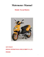
Matenance Manual   


Model: Focus/Matrix 


COPY RIGHT: 
 
KEEWAY INTERNATIONAL DEVELOPMENT CO.,LTD. 
 
FEB.2006 


Содержание Focus

Страница 1: ...1 Matenance Manual Model Focus Matrix COPY RIGHT KEEWAY INTERNATIONAL DEVELOPMENT CO LTD FEB 2006...

Страница 2: ...his manual please fell free to contact with KEEWAY INTERNATIONAL DEVELOPMENT CO LTD 2000 SZENTENDRE U 8 KOZUZO HUNGARY TEL 0036 26 500005 FAX 0036 26 312034 EMAI info keewaymotor com Our engineer are...

Страница 3: ...scooter user Those who will be servicing the scooter should carefully review the manual before performing any repair or services Major modifications and changes incorporated later will be advised to Q...

Страница 4: ...4 Index Termly maintenance and repair 2 Engine 3 Fuell and lubricate system 4 Electrical system 5 Frame 6 Maintenance information 7 General principles 1...

Страница 5: ...5...

Страница 6: ...6 GENERAL PRINCIPLES TYPE IDENTIFICATION 1 1 FUEL AND ENGINE OIL 1 1 BREAK IN PROCEDURE 1 1 PRECAUTIONS AND GENERAL INSTRUCTIONS 1 2 MAINTENANCE TOOLS 1 3 SPECIFICATIONS 1 4 CONTENTS...

Страница 7: ...nimum octane number is 90 or more ENGINE OIL For QIANJIANG CCI SYSTEM we recommend special engine oil you can choose high quality two stroke engine oil without being diluted if without special oil GEA...

Страница 8: ...Keep each other s safety when several persons do Inspect looseness and operating state of components after reassembling them Take high care of gasoline which is explosive and never use gasoline as lot...

Страница 9: ...io 6 9 1 Carburetor flat inhale stopper style Air cleaner dry Starting system electricity start and kicking start Lubricating system pressure lubricating ELECTRIC Ignition mode CDI Ignition timing 150...

Страница 10: ...torage battery 2 2 Spark plug 2 3 Cylinder head nut and exhaust pipe bolt 2 3 Cylinder head and cylinder 2 4 Fuel level line 2 4 Air cleaner 2 5 Throttle cable 2 5 Engine idle speed 2 5 Oil pump 2 6 G...

Страница 11: ...I I I I Cylinder head nut and exhaust pipe bolt T T T T T Cylinder head and cylinder C C C C Spark plug R R R R Air cleaner Clean every 3000KM 2000 miles Idle speed rpm I I I I I Throttle cable play I...

Страница 12: ...ery Inspect at initially 1000KM 600 miles 2 months andevery 6000KM 4000 miles 12 months thereafter Uncover seat and then remove the battery box cap in the Middle of helmet barrel Disconnect negative p...

Страница 13: ...ead cover bolt 3 Remove spark plug cap 4 Tighten the nuts evenly one by one to the their specified torque Tighten the nuts in the order indicated Tithtening torque Cylinder head nut 15 18N m Exhaust p...

Страница 14: ...thickness gauge Thickness gauge Spark plug gap 0 6 0 7 mm 0 024 0 028 inch Check the spark plug for burnt condition If abnormal replace the spark plug as indicated in the chart NGK TROCH REMARKS BPR7...

Страница 15: ...tall air cleaner filter core in the reverse order of removal CAUTION Before and during the cleaning operation inspect the core for tears A tore core must be replaced Be sure to position the filter cor...

Страница 16: ...ngine The amount of oil fed to it is regulated by engine speed and oil pump control lever which is controlled by amount of throttle opening Check the oil pump in the following manner to confirm correc...

Страница 17: ...r replace brake fluid every 2 years replace brake hose every 4 years Front brake fluid level Keep the scooter upright and place the handlebar staight Check brake fluid level by observing the lower lim...

Страница 18: ...rapped air exposes the machine and rider it is essential that after remounting the brake and restoring the brake system to the normal condition the brake fluid circuit be purged of air in the followin...

Страница 19: ...ith care the fluid reacts chemically with paint plastics rubber materials etc Rear brake Turn adjusting nut so that the the play of Brake lever is 15 25MM as shown in the illustration Brake shoe wear...

Страница 20: ...h the excessively worn tires will decrease riding stability and consequently invite dangerous situation It is highly recommended to replace the tire when the remaining depth of tire tread reaches the...

Страница 21: ...ecessary No Item N m Kg m 1 Front axle nut 55 60 5 5 6 2 Handle tightenging nut 37 44 3 7 4 4 3 Steering sterm locknut 37 44 3 7 4 4 4 Disc brake caliper fixing bolt 22 29 2 2 2 9 5 Disc brake master...

Страница 22: ...22 14...

Страница 23: ...Before lubricating each part clean off any rusty spots and wipe off any grease oil dirt of grime WARNING Be careful not to apply too much grease to the rear brake camshaft otherwise brake slippage wil...

Страница 24: ...inspection and servicing Bearings Oil seals crankshaft automatic clutch inspection cylinder head cylinder piston reed valve engine remounting oil seals bearings bushings crankshaft crankcase rear axle...

Страница 25: ...he engine from the frame Engine left side Kicking starter lever Clutch brake pad kit Driver left face V belt Driver belt right face Electric starter gear Super clutch Driven face Engine center Carbure...

Страница 26: ...muffler Remove cooling fan cover Remove cylinder cover Remove cooling fan Remove magneto nut with special tools remove magneto rotor and half circle key with special tools remove magneto stator and pa...

Страница 27: ...s board remove cylinder head and cylinder Place a cloth stopper beneath the piston and remove the circlip with a plier remove the piston pin and piston Remove the kick starter lever Remove side cover...

Страница 28: ...8 Remove starting driven ratchet wheel by removing the nuts Rmove fan and V belt Disassemble the movable drive face Remove electric gear press board electric gear And super clutch Remove starter motor...

Страница 29: ...29 Remove the clutch housing with the special tool drain gear oil remove rear axle nut remove rear wheel remove brake shoe and rear axle Remove the rear brake cam lever indicator plate and camshaft...

Страница 30: ...pring remove cotter pin and shaft remove main stand remove gearcase cover Remove paper gasket and middle gear assy Remove output gear assy remove carburetor remove intake pipe remove reed valve and pa...

Страница 31: ...31 Remove crankcase fixing shaft disassemble crankcase with special tools Remove crankcase with special tools Remove crankshaft bearing with special tools Sliding shaft Warning use a new sliding shaft...

Страница 32: ...y pressed down by hands to counter the clutch sparing load Releasing the hand suddenly may cause the following parts to fly apart nut clutch shoe spring CAUTION Do not attempt to disassemble the clutc...

Страница 33: ...place the removed bearing with a new one Remove bearing with special tool CAUTION Replace the removed bearing with a new one Remove the spacer Remove the oil seal from the gearcase cover with the spei...

Страница 34: ...with special tool warning use a new oil seal remove left crankcase bearing with special tool warning use a new one remove left crankcase shock absorber bushing with special tool warning use a new bush...

Страница 35: ...35 Remove right crankcase oil seal with special tool Warning use a new oil seal remove right crankcase bearing sliding bearing warning use a new bearing...

Страница 36: ...with solvent and lubricate with engine oil before inspecting Turn the inner ring and check to see that the inner rieng turns smoothly If it does not turn lightly quietly and smoothly or if noise is h...

Страница 37: ...the big end Move the rod up and down while holding the crankshaft rigidly to be sure that there is no rattle in the big end Wear on the big end of the connecting rod can be estimated by checking the m...

Страница 38: ...acer Seated on the scooter with the scooter on level ground increase the engine RPMs slowly and note the RPM at which the scooter begins to move forward Tachometer Standard 2900r min tolerance 300r mi...

Страница 39: ...condition of the inner clutch wheel surface for scrolling cracks or uneven wear Measure inside diameter of the clutch wheel with inside calipers Measure the diameter at several points to check for an...

Страница 40: ...turn smoothly If any stickiness or hitches are found visually inspect the lip of oil seal driven face sliding surface and sliding pins for wear or damage Driven face inspect the belt contacting surfac...

Страница 41: ...0 075mm 1 5778in after reworking the bore to an oversize be sure to chamfer the edges of ports and smooth the chamfered edges with emery paper To chamfer use a scraper taking care not to nick the wall...

Страница 42: ...on whose sliding surface is badly grooved ore scuffed due to overheating must be replaced Shallow grooves or minor scuff can be removed by grinding with emery paper of about 400 Piston pin bore Use a...

Страница 43: ...importance of using piston rings with end gaps with the limit Measure the piston ring free end gap to check the spring tension service limit 3 6mm 0 14in Fix the piston ring in the piston ring groove...

Страница 44: ...nation or emphasis These steps will be taken up for respective parts and components Oil seals fit the oil seals to the crankcase following the procedure below Replace removed oil seals with new ones L...

Страница 45: ...45 shock absorber bushing positon Install shock absorber bushing Install crankshaft bearing Press bearing into cankshaft Install crankshaft...

Страница 46: ...ebs 38 0 1mm 1 496 0 004in when mounting the crankshaft into crankcase it is necessaryto pull its left end into the crankcase with the special tool CAUTION Never fit the crankshaft into the the crankc...

Страница 47: ...QIANJIANG NO 1215 evenly to the mating surface of the right half of the crankcase Tighten the crankcase screws securely Check if crankshaft rotates smoothly Install gearcase bearing Install new bearin...

Страница 48: ...nstall middle gear position pin by installing middle gear axle gasket and thrust gasket install gearcase cover into crankcase and lock bolt tighten each screw screw oil drain nut 11 tightening torque...

Страница 49: ...49 install the bearing in the fixed driven face with the special tool install sliding bearing...

Страница 50: ...ly grease to the lip of oil seals and groove of inside of movable driven face QIANJIANG special super grease NOTE When reinstalling the movable face to the fixed face make sure that the oil seal is po...

Страница 51: ...en face all the way outside to provide the maximum ble clearance CAUTION the belt should be positioned so that the arrows on the belt periphery point the normal turning direction The V belt contact fa...

Страница 52: ...e should be used QIANJIANG supre grease Mount the three dampers on the movable drive plate and install it on the movable drive face Position the O RING on the movable drive face Install the movable dr...

Страница 53: ...ng torque 40 60N M 4 0 6 0kg m 29 0 43 5Ib ft fill grease in the groove provided inside sliding surface of the kick driven gear and install on the end of the crankshaft Wipe pff excess grease QIANJIAN...

Страница 54: ...90ml tighten the oil level bolt to the specified torque Tightening torque 9 15M M Starter assy Inject lubrication into start bearing and lubrication in the end of starter shaft QIANJIANG SPECIAL LUBRI...

Страница 55: ...as shown in the illustration Tightening toque 8 12N M 0 8 1 2kg m 6 0 8 5Ib ft PISTON install the piston rings on the piston The first and the second ring keystone ring NOTE Position the ring so that...

Страница 56: ...ot coincide with the grovve portion of the piston apply oil on the position and cyoinder wall surfaces and install the cylinder over the piston carefully tighten the cylinder head nut to the specifica...

Страница 57: ...tall oil hose Instake pipe install intake pipe Magneto clear crankshaft and magneto rotor install half circle key install paper gasket and stator coil and then fix them tighten to specified torque wit...

Страница 58: ...ng cover install fan guiding cover install pipe screw and screw for tightening muffler to their specified torque 8 12N m 0 8 1 2kg m 6 0 8 5Ib ft 18 28N m 1 8 2 8kg m 13 0 20 0Ib ft lubricate brake ca...

Страница 59: ...59 CHAPTER 4 FUEL AND LUBRICATION SYSTEM CONTENTS FUEL SWITCH CARBURETOR OIL PUMP...

Страница 60: ...pressure acts upon the diaphragm of the fuel switch and ti pressed down the spring which supports the diaphragm so that the fuel passageway is opened and fuel is fed to the carburetor When the engine...

Страница 61: ...r type Identification code Throat tube diameter Main jet size Idle needle jet size Oil needle clamp position Idle air adjusting screw Float height QIANJIANG WENLING CHINA equal vacuum PZ19JB 19mm 80 5...

Страница 62: ...positions of adjustable parts should not be changed except when compensation for the mixture ratio due to altitude differences or other climatic conditions When adjustment is necessary refer to the f...

Страница 63: ...63 CHAPTER 5 ELECTRICAL SYSTEM CONTENS IGNITION SYSTEM CHARGING AND LIGHTING SYSTEM STARTER SYSTEM FUEL GAUGE OIL LEVEL CHECK LIGHT AND TURN SIGNAL INDICATOR SWITCHS BARTERY...

Страница 64: ...gate of SCR As the SCR conducts the energy which has been charged in the capacitor is instantaneously discharged through the primary winding of the ignition coil CDI UNIT AND IGNITION COIL INSPECTION...

Страница 65: ...ectronic tester Ignition coil testing lead Use portable tester to check it Test the resistance between igntion ground wire andspark plug cap Ignition coil second resistance 12 18 KQ MAGNETO EXCITING C...

Страница 66: ...ywheel rotor turns AC generated in the charging coil flows to the regulator recifier which changes AC to DC The DC Then charges the battery Charging output check start the engine and keep it running a...

Страница 67: ...tester to measure the resistance between the lead wire and ground If the resistance checked is not correct replace the coil R regulator rectifier Disconnect the lead wire couple Using the pocket test...

Страница 68: ...witch and battery depressing the starter button while squeezing the front or rear brake lever energizes the relay causing the contact points to close which connects the starter motor to the battery St...

Страница 69: ...ground by plcing probe pins on each commutator segment and rotor core and on any two segments at various places With the brushes lifted off the commutator surface If the coil is found to be open circ...

Страница 70: ...empty positions Connect a 90 ohm resistor between the Y B and B W lead wires The fuel meter is normal if its pointer indicates the E empty position when the specified voltage is applied to the circui...

Страница 71: ...heck light turns on and remains lit When the turn signal switch is turned on and the turn signal light flashes the turn signal indicator light oil level check light also flashes both being not concurr...

Страница 72: ...72 SWITCH SWITCH SWITCH SWITCH...

Страница 73: ...oles Remove the caps NOTE After filling the electrolyte completely use the removed cap as the sealed caps of battery filler holes Do not remove or pierce the sealed areas of the elec trolyte container...

Страница 74: ...ours or 4 0A for 1 hour NOTE The current should be not more than 4A at any time After recharging wait for more than 30 minutes and apply multimeter to measure the battery voltage if the battery voltag...

Страница 75: ...EASSEMBLY AND REMOUNTING FRONT BRAKE BRAKE PAD REPLACEMENT CALIPER REMOVAL AND DISASSEMBLY CALIPER AND DISC INSPECTION CALIPER REASSEMBLY MASTER CYLINDER REMOVAL AND DISASSEMBLY MASTER CYLINDER INSPEC...

Страница 76: ...xad screw and remove decorating cap rear carrier and oil tank lock remove side cover by loosing side cover screw 3 unlock oil pump cap and remove it two tapping screw are exposed remove them remove ta...

Страница 77: ...2 removing under cover by loosing the left and right tapping screws under cover installation 3 The sequence if installation is ther reverse of removal front cover removal 1 Unscrew tapping screw and r...

Страница 78: ...PEDAL REMOVAL 1 Remove power lock housing by unscrewing bolt 3 remove legshield and pedal by unscrewing the four bolts Legshield and pedal installation 4 the sequence of legshield and pedal is the re...

Страница 79: ...79 HANDLE COVER REMOVAL 1 Remove front handle cover by unscrewing the six Tapping screws 2 Remove master cylinder by removing the bolt...

Страница 80: ...80 3 Disconnect throttle cable and oil pump cable 4 Remove rear brake cable adjusting nut...

Страница 81: ...81 Handle cover removal 5 remove all cables 6 Remove handle cover by unscrewing bolt Handle cover unstallation 7 The sequence of removal is the reverse of reomval...

Страница 82: ...ng 10 gearcase 11 valve mouth cap remove Remove the front brake caliper by removing the mounting bolts NOTE Do not operate the front brake lever while dismounting caliper remove mounting bolt remove t...

Страница 83: ...dust seal and bearing should be replaced with new ones AXLE SHAFT Check the axle shaft runout with a micrometer and replace it if the runout exceeds the limit Service limit 0 25mm 0 010in WHEEL RIM M...

Страница 84: ...llowing steps install this wheel bearing with the special tools as shown in this illustration CAUTION Install this wheel bearing for left side Install the brake disc as shown in photo When installing...

Страница 85: ...he calliper 1 disc brake assy 2 disc brake handle lever 3 tightening bolt 4 nut M6 5 master cylinder 6 tightening seat 7 bolt M6X23 8 brake hose assy 9 brake caliper 10 connecting board tightening bol...

Страница 86: ...and catch the brake fluid in a suitable receptacle CAUTION Nevere re use the brake fluid left over from the last servicing And stored for long periods Remove the calliper Remove the brake pads Remove...

Страница 87: ...nd wear Check the disc for wear with a micrometer Its thickness can be checked with disc and wheel in place Ralpace the dise if the thickness exceeds the service limit Service Limit 3 5 mm 0 14 in Wit...

Страница 88: ...iper refer to preceding bove pages WARNING Bleed air after remounting the calliper refer to above pages MASTER CYLINDER REMOVALAND DISASSEMBLY Remove the handlebar cover Refer to above page Disconnect...

Страница 89: ...e dust boot Remove the circlip with the special tool Remove the piston primary cup with return spring Remove the reservoir cap and diaphragn Drain brake fluid MASTER CYLINDER INSPECTION Inspect the ma...

Страница 90: ...also carry out the following steps CAUTION Wash the master cylinder components with fresh brake fluis before reassembly Never use cleaning solvent or gasoline to wash them Apply brake fluid to the cyl...

Страница 91: ...r brake light switch lead wires Remove the rear brake cable Remove throttle grip case Remove throttle cable 1 handle jointing assy 2 bolt GB5789 M10X1 25X45 3 nut GB6187 M10X1 25 4 left handlebar 5 th...

Страница 92: ...w locknut with special tool remove fornt fork assy by removing upper outer steel bowl NOTE Not drop the steering stem balls remove front fork remove bearing lower race by chisel Remove steel balls Num...

Страница 93: ...NSPECTION inspect the removed parts for the following abnormalities bearing race wear and brinelling Worn and damaged steel balls Distortion of steering stem or handlebar Inspect the suspension for da...

Страница 94: ...ball Apply grease when installing the upper and lower steel balls QTY upper 21 lower 21 Tighten the steering outer race with special tool then extrude it 1 8 1 4round NOTE adjustment will vary from sc...

Страница 95: ...ed torque 37 44N M NOTE After performing the adjustment and installing the handlebar Rock the front wheel forward and backward to ensure that there Is not play and that the procuder is accomplished co...

Страница 96: ...1 Tire 130 70 12 2 rear rim assy 3 brake pad kit assy 4 brake pad kit spring 5 rear brake tension 6 rear indicator 7 anti dust cover 8 rear brake camshaft 9 bolt M6 30 10 valve 11 nut M16 1 5 12 rear...

Страница 97: ...eel Remove brake shoes INSPECTION REAR RIM Measure inner diameter of rear rim hub with micrometer if measured diameter exceeds 110 7 replace it with a new one Brake shoes Check the brake shoe and deci...

Страница 98: ...Rear axle shaft side Install the protrusion of indicator plate to the groove of Camshaft When installing the brake cam shaft aligh the groove of camshaft With the slit of on cam shaft When installing...

Страница 99: ...99 SERVICING INFORAMTION Troubleshooting Batteru Vehicle Wiringd diagram Wire cable and brake hose routing Special tools Thread parts tightening torque Service data CONTENTS...

Страница 100: ...e CDI ignition coil unit 3 Clogged fuel hose 4 Clogged jets in carburetor 5 Clogged exhaust pipe Clean Replace Clean Clean Clean Noisy engine Noise appears to come from piston 1 Piston or cylinder wor...

Страница 101: ...ve face 12 Weakened movable driven face spring 13 Too rich fuel air mixture due to defective starter system Replace Replace Replace Adjust or replace Clean Adjust or replace Clean Clean or replace Ret...

Страница 102: ...uretor Change Clean Replace by hot type plug Replace Spark plug electrodes overheat or burn 1 Spark plug too hot 2 The engine overheats 3 Spark plug loose 4 Mixture too lean 5 Not enough engine oil Re...

Страница 103: ...tery polarity 1 The battery has been connected the wrong way round in the system so that it is being charged in the reverse direction Replace the battery and be sure to connect the battery properly Ba...

Страница 104: ...xcessively worn drum 9 Too much brake lever play Repair or replace Replace Clean disc and pads Replace Bleed air Replace Replace Replace Adjust Brake squeaking 1 Carbon adhesion on pad surface 2 Tilte...

Страница 105: ...105 WIRING DIAGRAM Dg M R B N B L Dg LR G W G B G Y R W BL W B R Y P W O LBL G R Y R B W N W...

Страница 106: ...106 WIRE CABLE AND BRAKE HOSE ROUTING...

Страница 107: ...107 carburetor...

Страница 108: ...108...

Страница 109: ...109 Ignition coil Starting relay CDI HORN POWER SWITCHH...

Страница 110: ...R DESCRIPTION 1 2 3 4 5 6 7 8 9 10 T01 T02 T03 T04 T05 T07 T08 T09 T10 T shape of sleeve sleeve tools 7mm 8mm 10mm 12mm 13mm flywheel remover sleeve 18mm 24mm screw remover cylinder pressure gauge pis...

Страница 111: ...111...

Страница 112: ...mp lock screw 5 9 Right crankcase lock bolt 10 12 Bearing press board lock bolt 10 12 Cylinder double head bolt 15 18 Motor tightening bolt 10 12 Left crankcase cover lock screw 10 12 Left crankcase c...

Страница 113: ...rance 0 15 0 35 0 0059 0 0138 0 8 0 0315 1st ring 0 02 0 06 0 0008 0 0024 Piston ring to groove clearance 2en ring 0 02 0 06 0 0008 0 0024 Piston pin bore 10 002 10 008 0 3938 0 3940 10 030 0 3949 Pis...

Страница 114: ...type Identification code PZ19JB Throat tube diameter 19mm Main jet size 80 Pilot jet size 57 5 Oil needle clamp position 3nd groove Idle air adjusting screw Extrude 1 2 1 2 1 turnout Float height 13 1...

Страница 115: ...Rear 110 mm 110 7 mm Brake shoe thickness Rear 4mm 2 5 mm Brake disc thickness front 4 0 0 2 3 mm Tire size Front rear 120 70 12 130 70 12 Tire surface thickness front rear 120 130 SUSPENSION Front s...

Отзывы: