background image

KC-P30

Commissioning

Installation manual V3.28

47

© KEBA

3) Hook in the housing cover at the top 

1

 and close it at the bottom 

2

. The

housing cover must glide into the guides without considerable resis-
tance. The housing cover must be correctly seated in the housing guide
on all sides.

4) Secure the housing cover with two screws at the bottom.

All covers are mounted and the charging station is ready for use.

9.4

Attach seal

Depending on the scope of delivery, devices are available for sealing the ter-
minal cover and the connection panel cover. If required, these can be used
to prevent or identify tampering attempts by unauthorized persons at charg-
ing stations with preconfiguration or special suitability (MID calibration valid-
ity).

To attach the seals, proceed as follows:

1) If necessary, open the covers of the charging station until the cover to be

sealed is accessible.

2) Loosen the right upper screw of the cover to be sealed.

Содержание KeContact KC-P30 e Series

Страница 1: ...KeContact KC P30 Charging Station Installation manual V 3 28 Translation of the original instructions...

Страница 2: ...e due to further technical developments Details presented may be subject to correction All rights reserved KEBA AG Headquarters Gewerbepark Urfahr 4041 Linz Austria Phone 43 732 7090 0 Fax 43 732 7309...

Страница 3: ...ar view 15 4 3 Top view 15 4 4 Type plate 16 4 5 Overview of variants 16 4 6 Options 19 5 Displays and operating elements 20 5 1 LED bar 20 5 2 Display optional 20 6 Mounting and installation instruct...

Страница 4: ...10 1 Replacing the fuse 49 10 2 Troubleshooting 49 10 3 Software update 50 10 4 Replace the SIM Card 50 10 5 Changing the cylinder lock 50 11 Disposal 52 11 1 Disposal of the charging station 52 12 Te...

Страница 5: ...d devices used in this manual are visual examples The figures and explanations contained in this manual refer to a typical device design The devices used by you may differ in their appearance We recom...

Страница 6: ...n CAUTION means that if the corresponding safety measures are not taken a potentially hazardous situation can occur that may result in slight bodily injury Caution means that damage to property can oc...

Страница 7: ...or use The charging station has to be installed vertically on a wall or on a floor mounted column The surface for the installation must be flat and suitably stable e g brick wall concrete wall The res...

Страница 8: ...pening the front part 4 Torx screws will break the manufacturer s seal and void the warranty claim For a war ranty claim there is a duty of proof of the customer that the defect which led to the defec...

Страница 9: ...he document Description of the charging station Assembly of the charging station Electrical installation of the charging station Commissioning of the charging station Maintenance of the charging stati...

Страница 10: ...idual current circuit breaker Type B Do not install or use a damaged device A damaged charging station must be taken out of commission and re paired or replaced by a qualified and authorized electrici...

Страница 11: ...nt they may only be removed after connect ing the cables Pull the charging cable out of the plug holder only by the plug and not by the cable The charging cable may not be not damaged mechanically kin...

Страница 12: ...for cylinder lock optional 3x RFID card optional 1x Installation materials Fig 3 2 Installation materials No Description e series b c x series 1 Cable gland M32x1 5 clamping area 10 21mm 1x 2 Lock nut...

Страница 13: ...nual V3 28 13 KEBA Mounting set for wall installation Fig 3 3 Mounting set for wall installation No Description e series b c x series 1 Hangar bolts M8x100 4x 2 Nut ISO 10511 M8 4x 3 Washer ISO 7089 8...

Страница 14: ...ion 1 Housing cover 2a RFID reader optional 2b Key operated switch optional 3 LED bar 4a Permanently installed charging ca ble optional 4b Charging socket with cover op tional 5 Holder for charging ca...

Страница 15: ...es 2 Flush mounting cable insertion openings M32 for supply line 3 Flush mounting cable insertion openings M20 for control line or Ethernet 4 3 Top view Fig 4 6 Top view 1 Type plate 2 Surface mountin...

Страница 16: ...ignation 5 Technical data 6 Marking of the approval 7 Type examination number 8 Accuracy class in accordance with EN 50470 1 3 9 CE marking 10 Public key information 11 Production site 12 Production d...

Страница 17: ...actor 3 phase 2 Energy meter x None 0 Energy meter not calibrated E Calibratable energy meter MID1 M Calibratable measuring instrument for electrical energy2 with national certification L Authorizatio...

Страница 18: ...eans of transducers on all phases to be contacted Support ing documents e g on the test mode can be requested from KEBA Not all variants deriving from the product designation are available with a cali...

Страница 19: ...ocess with MIFARE cards or tags according to ISO 14443 and ISO 15693 Fig 4 8 RFID 1 RFID reader 4 6 2 Key switch The key switch is used for authorizing a charging process with a key Fig 4 9 Key switch...

Страница 20: ...is only visible with activated power supply 5 2 Display optional Devices with energy meters P30 c series and x series have a dot matrix LED display Fig 5 11 Display The display may show different inf...

Страница 21: ...ing on the device model or for special materials the installation ma terials must be provided by the customer Proper installation is absolutely necessary and lies outside of the scope of responsibilit...

Страница 22: ...cold charging station is brought into a significantly warmer environ ment e g after longer transport in a cold environment condensation moisture may form in the device Before connecting the charging s...

Страница 23: ...strian and motorized traffic Do not install the charging station at locations where it is exposed to am monia or ammonia gas e g in or at stables The mounting surface must be sufficiently stable in or...

Страница 24: ...charging cable If several charging stations are installed adjacent to each other a distance of at least 200 mm between charging stations must be complied with Information We recommend mounting the ch...

Страница 25: ...1 cm 1 and then push upwards 2 3 Loosen the four screws of the connection panel cover and remove the connection panel cover upwards 4 Loosen the two screws of the terminal cover and remove the termina...

Страница 26: ...on To mount the charging station proceed as follows 1 Mark the 4 holes 1 in the designated location on the wall The supplied drilling template can be used for this purpose Fig 6 14 Drilling template 1...

Страница 27: ...gs on the charging station Pay attention to leak tightness 6 4 of the supplied washers can be used to compensate for any uneven ness and to ensure proper water flow behind the device If necessary plac...

Страница 28: ...wer connection phase conductor 1 2 Power connection phase conductor 2 3 Power connection phase conductor 3 N Power connection neutral conduc tor PE Power connection grounding con ductor DSW1 DIP switc...

Страница 29: ...Required tools The following tools are required for the electrical installation Flathead screwdriver for supply terminals blade width 5 5 mm Flathead screwdriver for terminals X1 X2 blade width 3 0 m...

Страница 30: ...aker I supply line I nominal current Dimensioning of the power supply line When dimensioning the power supply line also observe the possible reduc tion factors and the increased environmental temperat...

Страница 31: ...r times 10 For surface mounted cable installation the cable gland must be installed properly and screwed together sufficiently tight 7 3 2 Connecting the voltage supply The charging station can be con...

Страница 32: ...s use wire end sleeves 3 Insert the flat head screwdriver 5 5 mm into the supply terminal as shown The screwdriver must rest on the housing 4 Press the screwdriver straight into the terminal until the...

Страница 33: ...via the DIP switches is necessary For details see 8 1 DIP switch settings 7 3 3 Electrical connection to special systems of AC power supply Information The charging station can in principle be connect...

Страница 34: ...f the enable input must be activated with a DIP switch setting DSW1 1 to ON see 8 1 DIP switch settings In addition to the DIP switch setting starting a charging process using an en able input is depe...

Страница 35: ...nection diagram X1 7 5 Switch contact output X2 This function is not available with P30 e series The switch contact output X2 signal contact is a floating relay contact and can be used as a charging s...

Страница 36: ...7 18 Connection diagram X2 Safety extra low voltage Vcc 50 VAC F 0 5A current limiting protective equipment 7 5 2 Connection example The switch contact output can be used to switch off the charging st...

Страница 37: ...necessary e g during servicing The Ethernet1 connection X4 is designed as terminal block in LSA tech nology A hard wired communication e g for SmartHome or a charging net work may only be carried out...

Страница 38: ...le To prepare the connection cable proceed as follows 1 Strip the connection cable about 6 cm 2 Knock back approx 1 cm of shielding all over and wrap with conductive textile adhesive tape Connecting t...

Страница 39: ...and OFF Information Changes to the DIP switch settings only become effective after a restart of the charging station To restart press the Service button until the first beep approx 1 second or switch...

Страница 40: ...le UDP interface SmartHome Only available for P30 c series and x series For details see UDP Programmer s Guide Adjust current DSW1 6 to DSW1 8 Information Only one maximum value which is smaller than...

Страница 41: ...25 xx can be specified with the DIP switches DSW2 1 to DSW2 4 Each DIP switch has a specific value when it is set to ON A DIP switch set to OFF has the value 0 DSW2 1 ON value 1 DSW2 2 ON value 2 DSW2...

Страница 42: ...he SIM card Caution Material damage as a result of soiling Ensure that the connector panel remains clean so that no soiling wire ends etc gets inside the charging station through the SIM card slot 1 I...

Страница 43: ...KC P30 Configuration Installation manual V3 28 43 KEBA 2 Remove the SIM card...

Страница 44: ...n This indicates that the self test which is performed automatically at each startup was successful The following steps are necessary during the initial commissioning Activate commissioning mode Perfo...

Страница 45: ...ly the commission ing mode must be deactivated again To do this proceed as follows 1 Set DIP switch DSW2 8 to OFF see 8 1 DIP switch settings 2 Restart the charging station by pressing the Service but...

Страница 46: ...seal can be attached Caution For correct installation of devices with a calibratable energy meter the charge point operator must apply a seal For devices with MID certification at least the terminal c...

Страница 47: ...and the charging station is ready for use 9 4 Attach seal Depending on the scope of delivery devices are available for sealing the ter minal cover and the connection panel cover If required these can...

Страница 48: ...ing cap 4 Screw the screw with the sealing cap back into the cover 5 Close the cover of the sealing cap 6 Thread the sealing wire through the opening of the sealing cap over the screw and place the se...

Страница 49: ...panel cover or terminal cover it may only be removed by an authorized person After changing the fuse the seal must be replaced 3 Using a screwdriver press into the opening of the fuse holder 4 Screw...

Страница 50: ...observed Information A software update process on the charging station is indicated by a slow or ange flashing of the LED bar 10 4 Replace the SIM Card To replace the SIM card proceed as follows 1 Re...

Страница 51: ...push in the coding pin to turn the lock nose 2 Turn the lock nose 1 so that it points vertically up wards in the removal position of the key 3 Turn the key 180 so that the lock nose faces down ward 4...

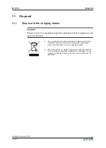
Страница 52: ...electronic devices The symbol with the crossed out waste container means that electrical and electronic devices including their accessories must not be disposed of in the household garbage The materia...

Страница 53: ...Power supply Power consumption e series Rated supply voltage Europe 230 V Internal consumption Idling 2 W plugged in 3 W charging 5 5 W Rated current configurable 10 A 13 A 16 A 20 A 25 A 32 A 1 phas...

Страница 54: ...2 3 Cable Socket Cable versions For rating see rating plate on the cable Type 1 cable up to 32 A 230 V AC in accordance with EN 62196 1 and SAE J1772 Type 2 cable up to 32 A 400 V AC in accordance wit...

Страница 55: ...rface Type A USB 2 0 Hi Speed Max output power 500 mA Enable input Type External potential free switch contact Type of terminal Spring type terminal Cross section 0 08 4 mm2 AWG 28 12 Stripping length...

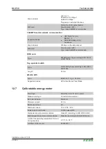
Страница 56: ...693 Key operated switch Type Profile half cylinder according to EN 1303 or DIN 18252 Length 30 mm WLAN Wifi Type IEEE 802 11 b g n 2 4 GHz Supported modes AP Ad hoc Mode Client Mode 12 7 Calibratable...

Страница 57: ...Customer identification Signature Long term memory for measurement data in the device 20 000 charging sessions Instant display of the measurement data Device specific display with lighting and dimmer...

Страница 58: ...tion manual V3 28 58 KEBA Fig 12 20 Dimensions in millimeters Version with charging cable and holder Height Width Depth 643 mm 240 mm 142 mm Weight Approx 5 3 7 8 kg depending on device version Fig 12...

Страница 59: ...tage Directive 2014 30 EU Electromagnetic Compatibility Directive 2014 53 EU Radio Equipment Directive RED 2011 65 EU Directive on the restriction of the use of cer tain hazardous substances RoHS 2012...

Страница 60: ...assa internetosoitteessa 2 FR Le soussign KEBA AG d clare que l quipement radio lectrique du type 1 est conforme la directive 2014 53 UE Le texte complet de la d claration UE de conformit est disponib...

Страница 61: ...naslednjem spletnem naslovu 2 SV H rmed f rs krar KEBA AG att denna typ av radioutrustning 1 verensst mmer med direktiv 2014 53 EU Den fullst ndiga texten till EU f rs kran om verensst mmelse finns p...

Страница 62: ...llation manual V3 28 62 KEBA Variants XI Authorisation 0 R K no authorisation RFID Keyswitch XII Customer options xx Options for individual customer versions not relevant for EU Declaration of Conform...

Отзывы: