


Page 4.1 - 6
COMBIVERT R6-S
© KEB, 2008-02
Start-up
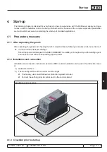
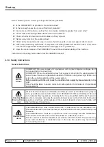
Stationary
Connection
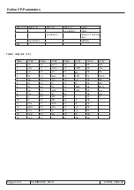
The COMBIVERT R6 is designed for fixed connection only as discharge currents of > 3.5
mA may occur especially when using EMI filters. In accordance with EN 61800-5-1 the
following cross sections of the protective earth conductor must be used:
Cross-section
of the phase
conductors
Minimum cross-section of the protective earth conductor
<10 mm²
10 mm² CU or
additional connection terminal for a second protective earth conductor
with the same cross-section as the phase conductor
10…16 mm²
Protective earth conductor with cross-section as phase conductor
16…35 mm²
Protective earth conductor with a cross-section of 16 mm²
>35 mm²
Protective earth conductor with a cross-section of 50 % of the phase
conductor.
Insulation
Measurement
When doing an insulation measurement in accordance with VDE 0100/ Part 620, the po-
wer semiconductor of the unit and existing radio interference filters must be disconnected
because of the danger of destruction. This is permissible in compliance with the standard,
since all inverters are given a high voltage test in the end control at KEB in accordance with
EN 50178.
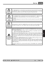
Different Earth
Potentials
When using components without isolated inputs / outputs, it is necessary that equipotential
bonding exists between the components to be connected (e.g. through the equalizer). Dis-
regard can cause destruction of the components by the equalizing currents.
Prevent
Disturbances
A trouble-free and safe operation of the COMBIVERT R6 is only guaranteed when the con-
nection instructions below are strictly followed. Incorrect operation or damage may result
from incorrect installation.
Pay attention to mains
•
voltage.
Install power cables and control cables separately (> 15 cm separation).
•
Use shielded / twisted control lines. Lay shield at one side to COMBIVERT R6-S to
•
PE !
Only use suitable circuit elements to control the logic and
•
analog inputs, whose contacts
are rated for extra-low voltages.
Housing of the COMBIVERT R6 must be well earthed. Screens of larger power cable
•
must be directly and securely attached to both the inverter PE terminal and the motor
ground
terminal. Remove paint finish where necessary.
Ground the cabinet or the system earth star point with the shortest connection to mains
•
earth (avoid earth loops)
Use exclusively the line commutation throttle specified by KEB.
•
The average value of the supplied DC
•
current may not exceed the maximum DC
current.
If several
•
frequency inverters are connected to the COMVIBERT R6-S the max. per-
missible network component currents and DC link capacities of all connected frequency
inverters must be considered during supply operation (see technical data).
Automatic
Restart
The COMBIVERT R6 can be adjusted by such way that the inverter restarts automatically
after an error case (e.g. broken phase line). System design must take this into account, if
appropriate, and additional monitoring or protective features added where necessary.
Содержание combivert R6-S
Страница 1: ...APPLICATION MANUAL Mat No Rev 00R6SEA K130 1 A GB KEB COMBIVERT R6 S Version 1 3 ...
Страница 2: ...Page 1 1 2 COMBIVERT R6 S KEB 2008 02 Introduction ...
Страница 4: ...Page 1 1 4 COMBIVERT R6 S KEB 2008 02 Introduction ...
Страница 14: ...Page 1 2 6 COMBIVERT R6 S KEB 2008 02 Product overview ...
Страница 28: ...Page 2 1 6 COMBIVERT R6 S KEB 2008 02 Fundamentals ...
Страница 34: ...Page 2 2 6 COMBIVERT R6 S KEB 2008 02 Password structure ...
Страница 40: ...Page 3 1 2 COMBIVERT R6 S KEB 2008 02 Parameter overview 3 1 1 Parameter list F5 A E and H 3 1 3 ...
Страница 116: ...Page 3 8 2 COMBIVERT R6 S KEB 2008 02 Special functions 3 8 1 Program timer counter 3 8 3 ...
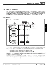
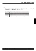
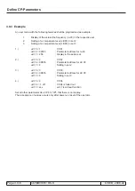
Страница 130: ...Page 3 9 10 COMBIVERT R6 S KEB 2008 02 Define CP Parameters ...
Страница 140: ...Page4 2 2 COMBIVERT R6 S KEB 2008 02 Start up ...
Страница 144: ...Page4 2 6 COMBIVERT R6 S KEB 2008 02 Start up ...
Страница 146: ...Page 5 1 2 COMBIVERT R6 S KEB 2008 02 Error assistance 5 1 1 General 5 1 3 5 1 2 Error messages and their causes 5 1 3 ...
Страница 150: ...Page 5 1 6 COMBIVERT R6 S KEB 2008 02 Error assistance ...
Страница 158: ...Page 6 1 8 COMBIVERT R6 S KEB 2008 02 Project design ...
Страница 160: ...Seite 7 1 2 COMBIVERT R6 S KEB 2008 02 Annex 7 1 1 Keyword index 7 1 3 ...
Страница 166: ......
Страница 167: ......


