


8
1
3
KEB COMBIVERT F5
Name: Basis
10.04.02
Special Operation
Section
Page
Date
©
KEB Antriebstechnik, 2002
All rights reserved
Chapter
8. Special Operations
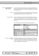
8.1 Temperature
Control
This function serves only as temperature control for watercooled inverters. The
water cooling system can be switched on with a pneumatic or solenoid valve.To
avoid pressure surges, the valves for a temperature control must be inserted before
the cooling circuit. All usual valves can be used. Depending on the used valve the
switching electronics must be provided by the customer. The control occurs via the
analog outputs 3 and 4 and the flags, which are assigned to the digital outputs. Two
functions must be programmed, because the temperature ranges of the inverter
and the motor are different.
Attention! Do not use relay outputl
Period (An.46, An.52)
The respective functions are adjusted with these parameters (temperature control
of the power controller or the motor).
The period determines the cycle time in which the output is switched. The period
can be adjusted in a range from 1,0...240,0 s.
The heat sink temperature which shall be controlled is entered with Offset. The
temperature is in a range from 30
∞
C...50
∞
C for inverters (heat sink temperature/
see power unit data) and in a range from 40
∞
C ...80
∞
C for motors. The adjustment
occurs in percentual values (1% = 1
∞
C).
The gain determines the max.temperature. The adjustment occurs via a factor and
is calculated as follows.
Max. temperature [
∞
C] = An.44 + (100% / An.43)
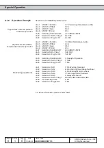
Adjustments for the Controller
An.41 = 12 :
Power stage temperature
An.44 = 30 %
Beginning of the temperature control
An.43 = 5,00
Gain for the max. temperature, see formula above
An.46 = 20 s
Period (cycle time)
do.06 = 42 :
ANOUT3 PWM, switching condition 6
do.22 = 64 :
Selection for flag 6
do.33 = 64 :
Selection and assignment of the output terminal
The switching period T
an
of the output is calculated by the following formula if the
heat sink temperature is within the adjusted temperature range.
T
an
=(Max. temp.-setpoint temp.)+(heat sink temp.-setpoint temp.)
∑
Period
max. temp.-min.temp.
Offset X (An.44, An.50)
Gain (An.43, An.49)
Function (An.41, An.47)
Example
8.1.1 Parameter
Description