20
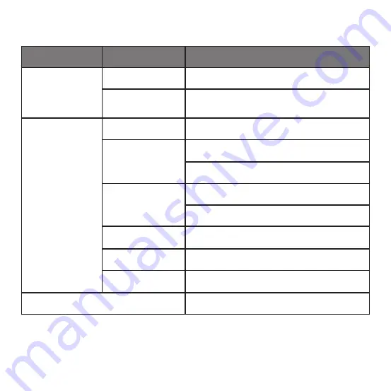
Table-4 Service menu when the wired controller connects to the IDU through the CN2 port
Level 1 Menu
Level 2 Menu
Content Settings
ROOM SENSOR
CONFIGURATION
LOCATION
WIRED CONTROLLER / INDOOR UNIT(default)
OFFSET
-5°C/ -4°C/ -3°C/ -2°C/ -1°C/ 0°C (default) / 1°C/
2°C/ 3°C/ 4°C / 5°C/-5°F/ -4°F/ -3°F/ -2°F/ -1°F/
0°F(default) / 1°F/ 2°F/ 3°F/ 4°F/5°F
WIRED CONTROLLER
CONFIGURATION
COOLING ONLY
ENABLED/ DISABLED(default)
SETTING CONFIGURATION
Temperature increment (°C display only):
0.5 / 1(default)
Fan speeds: 3 / 7 (default)
TEMP
SETTING LIMITS
Cooling mode minimum: 17 ~ 30°C(62 ~ 86°F), default: 17°C(62°F)
HEATING MODE MAXIMUM: 17 ~ 30°C(62 ~ 86°F), default: 30°C(86°F)
INFRARED RECEIVER
Sets if the wired controller can receive the remote controller signal and
forward the signal to the IDU ENABLED (default)/ DISABLED
AUTO RESTART
ENABLED (default)/ DISABLED
CLEAN FILTER REMINDER
PERIOD
NONE(default) / 1250HOURS / 2500HOURS / 5000HOURS /
10000HOURS
IDU ADDRESSES
Sets the IDU communication address (0 ~ 63#)
Содержание KCT-03 SRPS
Страница 4: ......
Страница 32: ...28 2 Display Description Main display interface Fault display interface Fig 24 ...
Страница 68: ......


