13
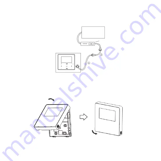
2-5-6 For the non 2nd generation DC IDU, the wired controller needs to be interconnected to the 5-core terminal on the IDU display panel through
the CN2 port. See Fig. 12.
The following standard connection line sets
and
as configured for the following wired controller accessories.
After adjusting the front cover, buckle the front cover; avoid clamping the communica- tion switching wire during installation. (Fig. 13)
2-6
Front cover installation
Indoor Unit
Wired Controller
Display Panel of
Indoor Unit
Fig. 12
Fig. 13
Содержание KCT-03 SRPS
Страница 4: ......
Страница 32: ...28 2 Display Description Main display interface Fault display interface Fig 24 ...
Страница 68: ......


