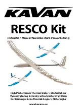
Kavan RESCO Kit Скачать руководство пользователя страница 5

5

•  Bevel the root ribs of the wing outer panels using 

the supplied 7° dihedral jig. Trial fit the carbon wing 

joiner into the respective bays; there should be a ti-

ght fit, no play. If there is a significant play, put some 

epoxy to appropriate area of the joiner and sand as 

necessary once the glue hardens. (Fig. 42+43)

•  Glue the 3 mm liteply root ribs with 3 mm beech 

alignment pins. (Fig. 44+45)

•  Prepare everything for the airbrake servo installati-

on; glue the fibreglass plate to the lower surface of 

the airbrake and the liteply magnet holder to the rear 

of the servo bay. (Fig. 46)

•  The spoiler servo is to be installed using a balsa spa-

cer (not supplied in the kit) - depending on the di-

mensions of your servo. The servo must not 

be higher than the wing ribs; it may not obstruct the 

spoiler when closed (do not forget to take in account 

the double sided foam tape you will use to secure the 

servo!). Apply epoxy or medium cyano to the servo 

spacer (if used) and the entire balsa lower sheeting 

of the servo bay in order to be sure the double sided 

foam tape will stick.

Covering

•  Thoroughly sand the surface of all parts with No. 

360-400 sandpaper and carefully vacuum all the dust 

(the iron-on film does not stick well to a dusty sur-

face; the dust also contains hard grains released off 

the sandpaper capable to ruin the smooth coating of 

your sealing iron quickly).

•  Use as light iron-on film as you can get (transparent 

Oracover, Oralite etc. – not supplied in the kit). Follow 

the instruction manual supplied with the covering 

film of your choice please.

Hinging the Control Surfaces

Use strips of a high quality hinging tape (available in 

hobby shops) or strips of the same iron-on film you 

used for the covering. Remember to apply the tape 

with the control surface deflected to the limit in order 

to get free movement of the particular control surface.

Tail Surfaces and Tail Boom Installation

•  Attach the wing centre section to the fuselage and 

the horizontal tailplane to the tail boom; secure them 

with nylon bolts. Slide the carbon fairing and the ply 

fairing former onto the carbon tube tail boom. Insert 

the tail boom into the fuselage (no glue yet). Check 

again that the fuselage is straight; align the wing and 

the tailplane with their trailing edges parallel. Once 

satisfied, epoxy the tail boom and the carbon fai-

ring with its former to the fuselage. Before the glue 

hardens double check the correct alignment of the 

wing, fuselage and tailplane.

•  Use medium CA to glue the fin into the tail boom; be 

sure it is square to the horizontal tailplane.

Pushrod Installation (Fig. 47)

•  Tack glue the pushrod tubes to the 1.5 mm balsa 

pushrod tube holder.

•  Tack thick cyano to the balsa and insert the pushrod 

tubes into the carbon fuselage tube (with a little help 

of pushrod strings).

•  Insert the pushrod strings into the respective tubes 

from the tail end.

Servo Installation

Rudder and Elevator Servos Installation (Fig. 48)

•  Make a „Z“ bend on the end of the pushrod and fit it 

to the servo horn.

•  A

lternatively you can use a closed loop of a Kevlar thre-

ad (not supplied in the kit) to hook the rudder – it might 

save some weight. In that case you will need to install 

just one pushrod for the elevator.

Spoiler Servo Installation (Fig. 49)

•  The spoiler servo is to be installed using a balsa spa-

cer (not supplied in the kit). The thickness of the spa-

cer depends on the dimensions of your servo. The 

servo must not be higher than the wing ribs 

(in may not obstruct the spoiler when closed).

•  Glue the fibreglass plate to the spoiler.

•  Glue the magnets to the spoiler and wing using the 

supplied liteply holder.

•  Please check the polarity of magnets first – they must 

attract each other.

Pushrods and Towhook (Fig. 50)

•  The pushrod tubes are to be located over the liteply 

plate.

•  Thread them through the holes in the former next to 

servos.

•  Install the towhook to the pre-drilled holes.

Wing Root Rib (Fig. 51)

•  Glue the magnets using 5min epoxy.

Pushrod Installation – The Tail End (Fig. 52)

•  Trial fit the rudder and elevator horns (no glue yet), 

bend the ends of pushrod strings to the „L“ shape and 

thread them through the hole in the horn. Once sa-

tisfied, cyano the horns into the rudder and elevator.

•  Please note the servo arms have to be square to the 

pushrods in the neutral.

•  Glue the end of the rudder pushrod tube to the fuse-

lage.

•  The end of the elevator pushrod tube remains free, no 

glue here.

Towhook (Glider Version) (Fig. 53)

•  Keep the recommender CG position 78 – 82 mm be-

hind the wing leading edge.

•  Set the towhook 10 mm in front the CG for the first 

flight.

•  You have to loose the front screw in order to move 

the towhook.

Power System Installation (Electric Version) 

(Fig. 54-56)

•  Fit your motor using appropriate screws to the fi-

Содержание RESCO Kit

Страница 1: ...vanrc eu Instruction Manual Návod ke stavbě Bauanleitung RESCO Kit High Performance Thermal Glider Electric Glider Vysokovýkonný termický větroň motorový větroň Der leistungsstarke Thermik Segler Motorsegler ...

Страница 2: ...z překážek stromů elektrických vedení apod Vyhledejte bezpečné místo mimo cesty a veřejné komunikace dbejte na bezpečnost přihlížejících diváků VORSICHTSMAßNAHMEN Dieses R C Modell ist kein Spielzeug Benutzen Sie es mit Vorsicht und halten Sie sich an die Anweisungen in dieser Anleitung Bauen Sie das Modell gemäß der Anleitung zusammen Modi fizieren und verändern Sie das Modell nicht Bei Nichteinh...

Страница 3: ... you with a top quality kit and instructions but ultimately the qu ality and flyability of your finished model depends on how you build it therefore we cannot in any way gua rantee the performance of your completed model and no representations are expressed or implied as to the performance or safety of your completed model MODEL ASSEMBLY Tail Surfaces Trial fit the parts of the horizontal stabiliz...

Страница 4: ...late 5 mm ply central plate and rear 0 8 mm ply longer slanted edge plate Prevent the epoxy hardening inside the bays put the parts together with the carbon joiner inserted then immediately remove the joiner do not forget cleaning the joiner using a paper tissue and rubbing alcohol before the glue sets Fig 19 22 Slide all ribs onto the mains spar shear webbing no glue yet Bind the joiner bays with...

Страница 5: ... edges parallel Once satisfied epoxy the tail boom and the carbon fai ring with its former to the fuselage Before the glue hardens double check the correct alignment of the wing fuselage and tailplane Use medium CA to glue the fin into the tail boom be sure it is square to the horizontal tailplane Pushrod Installation Fig 47 Tack glue the pushrod tubes to the 1 5 mm balsa pushrod tube holder Tack ...

Страница 6: ...g descending or ascending if your RESCO already tends to ascend you will have to incre ase motor down thrust turn the motor off and test RESCO s gliding characteristics Keep your RESCO into the wind and observe its flight If turns without power right although under power it kept the straight direction it will be necessary to incre ase motor right side thrust and vice versa If descends too much wit...

Страница 7: ...ejte jen s pomocí zkušeného modeláře Poznámka My jako výrobce stavebnice Vám můžeme zaručit stavebnici prvotřídní kvality s podrobným návo dem ale letové vlastnosti a výkony závisí výhradně na tom jak model dokončíte Vy Protože nemáme žádnou kontrolu nad tím jak model dokončíte nemůžeme pře vzít a nemůže být ani předpokládána jakoukoliv odpo vědnost za případné škody způsobené nebo související s p...

Страница 8: ... Vytvořte zrcadlově shodný pár žeber Obr 16 17 Mezi připravená středová žebra epoxidem vlepte desku pro upevňovací šrouby křídla Obr 18 Epoxidem slepte díly stojiny hlavního nosníku krát kou 0 8 mm překližkovou spojku s otvorem ve středu na přední stranu hlavního nosníku dlouhou spojku na zadní stranu hlavního nosníku Na koncích stojiny nosníku vytvořte kapsy pro uhlíkové spojky z kratší obdélníko...

Страница 9: ...1 2 3 4 5 6 7 8 9 10 11 9 ...

Страница 10: ...12 13 14 15 16 17 18 19 20 21 22 23 10 ...

Страница 11: ...24 25 26 27 28 29 30 31 32 11 ...

Страница 12: ...33 34 35 36 37 38 39 40 12 ...

Страница 13: ...13 41 42 43 44 45 46 47 ...

Страница 14: ...14 48 49 50 51 52 53 ...

Страница 15: ...15 55 56 54 ...

Страница 16: ...used The servo must be located as high as possible as close to the spoiler as possible Výšku podložky volte dle šířky krabičky serva Servo musí být co nejvýše co nejblíže k brzdě Die Höhe der Unterlage wählen Sie nach der Breite der Servo Schachtel Servo muss möglichst hoch und möglichst nahe bei der Bremse sein CG Position 78 82 mm Těžiště 78 82 mm Schwerpunkt 78 82 mm 10 mm 10 mm 40 mm ca 75 60 ...

Страница 17: ...te použili pro potah Pásku lepte vždy na kormidlo vychýlené do krajní polohy aby vznikla dostatečná vůle pro pohyb kormidla Upevnění nosníku ocasních ploch a ocasních ploch Střední část křídla upevněte šrouby k trupové gondo le a vodorovnou ocasní plochu k ocasnímu nosníku Na přední konec ocasního nosníku nasuňte uhlíkový přechod s překližkovou přepážkou a na sucho bez lepení zasuňte do trupové go...

Страница 18: ...vu zkontrolujte klouzavý let Nyní jste připraveni vykonat první start modelu RESCO na vlečné šňůře nebo gumicuku Doporučujeme vleč nou šňůru o délce 100 150 m s praporkem nebo gumi cuk odpovídající letové hmotnosti a rozpětí modelu Verze s elektrickým pohonem Zapněte vysílač a potom přijímač regulátor a zkon trolujte znovu funkci celého modelu Zapněte motor na plný plyn Model vypusťte je mírným šv...

Страница 19: ...chen Regeln und auch mit Bauernverstand fliegen werden Wenn Sie gerade mit RC Modellen beginnen bitten Sie um Rat in Ihrem Modellbaugeschäft oder einen erfahrenen Modellbauer im lokalen Modellba uklub damit Sie einen guten Instruktor finden Vor dem Bau Bauen Sie das Modell genau nach der Anleitung Än dern Sie oder passen Sie das Modell auf keine Weise an Sonst riskieren Sie dass das Modell gefährl...

Страница 20: ...o torspanten versichern Sie sich dass die Löcher darin zu Ihrem Motor passen Richten Sie die Löcher nach Ihrem Bedarf zu oder als letzte Möglichkeit machen Sie neue die genau zu Ihrem Motor passen Abb 13 Flügel Flügel Mittelteil Kleben Sie die Rippen des Flügel Mittelteils mit Epoxid zusammen Für eine genaue Ausrichtung stecken Sie die Stifte in die vorbereiteten 3 mm Lö cher Achtung Stellen Sie e...

Страница 21: ...e Oberseite des Ser vogehäuses fast in der Ebene mit der Kante der Mit telrippe ist achten Sie auf die Stärke des Klebebands mit dem Sie das Servo befestigen Damit das Klebe band gut hält tragen Sie Epoxid auf die Servoplatte und die gesamte feste Beplankung zwischen den Mittelrippen auf oder vergießen Sie sie mit einem Sekundenklebstoff Bespannung des Modells Schleifen Sie alle Teile des zu bespa...

Страница 22: ...Motor mit geeigneten Schrauben am Motorspant den Drehzahlregler und Antrieb sakku befestigen Sie im Kabinenraum mit Hilfe von Klettband Prüfen Sie mit eingeschalteten RC Set ob sich der Motor in der richtigen Richtung dreht gegen den Uhrzeigersinn von vorne gesehen Wenn dies nicht der Fall ist programmieren Sie den Regler neu oder tauschen Sie beliebige zwei von drei Kabeln zwischen dem Motor und ...

Страница 23: ...t er geeignet für wenig er fahrene Piloten die noch nicht optimale Größe der Ru derausschläge einstellen können Bei den Flugtesten der Prototypen schien uns als die beste Schwerpunktl age 78 mm der erfahrene Pilot kann den Schwerpunkt nach dem Einfliegen des Modells noch ein bisschen mehr nach hinten zu schieben und er kann einzigartige Reaktion auf kleine Thermik und sensitiveres Steuern genießen...

Страница 24: ...teply 2pc Překližka topol 3 mm přepážky trup 2ks Pappelsperrholz 3 mm Trennwände Rumpf 2 Stück Firewall 3 mm Plywood 1pc Překližka 3 mm motorová přepážka 1ks Sperrholz 3 mm Motorspant 1 Stück Nose Sanding Jig 3 mm Liteply 3pc Překližka topol 3 mm přípravek broušení předek trupu 3ks Pappelsperrholz 3 mm Schleifwerkzeug Vorderrumpf 3 Stück Wing Parts Hromadně balené díly křídlo Lose verpackte Flügel...

Отзывы: