
SYSTEM REQUIREMENTS
GO Servo USB Programmer
Instruction Manual
• Operating Voltage: USB (5 V/ 500 mA)
• Operating System: Windows® XP/Vista/7/8/10 (32/64bit)
• Compatible Servos: KAVAN GO-10xx Series servos
SOFTWARE INSTALLATION
1. Download the software package from the KAVAN website (https://www.pelikandaniel.com/dld/KAVAN0.11.zip) or
scan the QR code to download it. Decompress the .zip file, save it on your PC and run the “KAVAN0.11.exe“ file.
2. Plug the USB programmer in a free USB 2.0 port of your PC. The PC detects the device and the driver installation starts
automatically; it might take some time depending on your system. The PC announces the installation progress; once
finished, the restart of your PC might be required (the actual dialog window depends on your system).
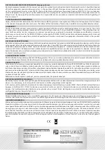
3. Open the programmer soft-
ware, “Adapter plug-in!” will
appear in the information
window. If not, you will have to
remove the USB programmer
and plug it again.
4. Connect your GO-10xx series
servo to the USB programmer;
the software recognizes it au-
tomatically and will read the
servo data and settings. “Servo
plug-in!” will appear in the in-
formation window and servo
name, manufacture date and
firmware version will appear
in the Servo Information box.
Green LED on the USB progra-
mmer flashes.
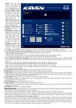
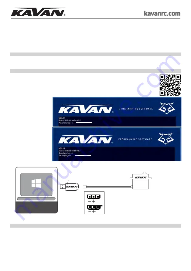
Wiring Diagram
|
►
►
s
+
-
USB 2.0
Windows XP/Vista/7/8/10
(32/64bit) computer
GO Servo
Programmer
GO-10xx Series Servo
White Wire
Konektor Tx
Hitec
Konektor Hitec
Rx
Konektor Futaba
Rx
JR/UNI
Futaba
S
S
Note:
If the servo is not detected, it might be connected to the USB programmer in a wrong way. Remove the servo and programmer and
plug them again correctly (the signal wire – marked with a white stripe – has to be connected to the “S” pin of the servo programmer socket).
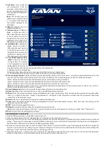
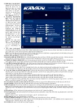
THE PROGRAMMER SOFTWARE FUNCTIONS
1. Information Window
– displays the connection status of your programmer and servo and other messages.
2. Servo Angle:
Maximal servo rotation angle range setting. The default range is ca 120° within the regular RC signal pulse width range
(900~2100 µs); ca 180° within the max. signal pulse width range (500~2500 µs).
Range:
1~255
3. Servo Neutral:
Servo neutral (centre) position setting.
Range:
-127~127
4. Damping Factor:
Servo damping setting – adjust the characteristics of the servo when stopping.
Range:
50~600
5. PWM Power:
Adjusts the servo output power. The higher the power, the higher the speed and torque of the servo – indeed also the
current consumption will be higher.
Range:
39.2~100.0%
6. Sensitivity:
Servo sensitivity (Dead Band) setting. The higher sensitivity the narrower the dead band – servo moves only if the change of
the signal pulse width is bigger than the dead band width. Too high setting may cause servo jitter in some applications.
Range:
Ultra High (ca 1 µs dead band) – High (ca 2 µs) – Medium (ca 3 µs) – Low (ca 4 µs)
LED