Kaman Aerospace Corporation
Kaman Precision Products
Copyright © 2019
PART NO: 860510-001A
Last Revised: 2019.10.22
Measuring & Memory Systems
217 Smith Street
Middletown, CT 06457
www.kamansensors.com or 860-632-4442
Page 1 of 1
2
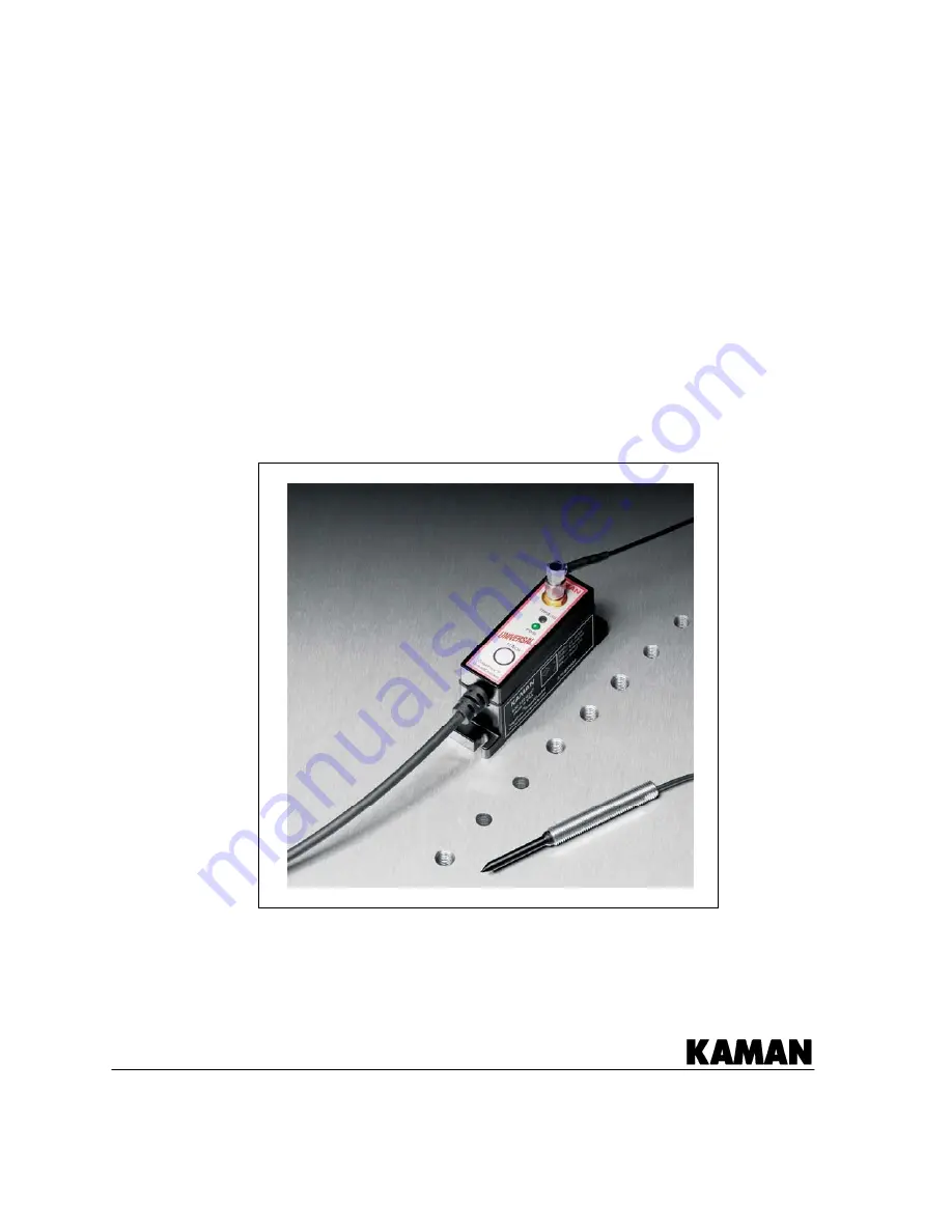
ThreadChecker
TM
Noncontact Thread Detection
System
User’s Manual


