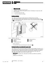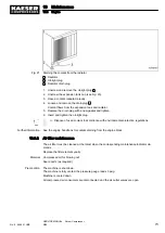
The machine is equipped with a plastic fuel tank to save weight.
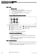
The securing strap of the fuel tank is working properly as soon as the locking mechanism is proper‐
ly tightened with the correct tool
Your manual force is sufficient to tighten the screw of the locking mechanism!
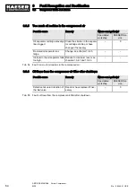
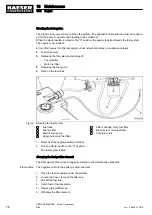
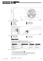
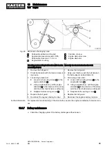
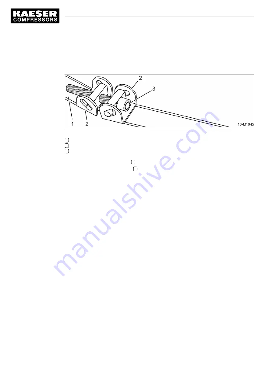
Fig. 24 Checking the securing strap
1
Securing strap
2
Locking mechanism
3
Screw
1. Ensure that the securing strap
1
is firmly gripped.
2. If required, re-tighten the screw
3
manually.
3. Check again that the securing strap is firmly gripped.
The fuel tank is properly secured.
10.3.3.2 Option ne
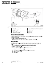
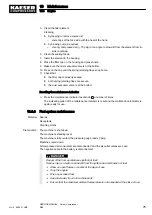
Maintaining the fuel water trap
The fuel water trap is positioned between the fuel tank and the fuel pre-filter.
It protects the fuel pump against water that separates out from the diesel and against early wear.
Material Wrench
Receptacle
Cleaning cloths
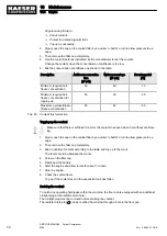
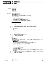
Precondition The machine is shut down.
The machine is standing level.
The machine is fully vented, the pressure gauge reads 0 psig.
Machine cooled down.
The negative cable to the battery is disconnected.
10 Maintenance
10.3 Engine
78
SERVICE MANUAL Screw Compressor
M26
No.: 9_9446 01 USE
Содержание M26
Страница 1: ...SERVICE MANUAL Screw Compressor M26 No 9_9446 01 USE...
Страница 187: ...13 Annex 13 2 Pipeline and instrument flow diagram P I diagram No 9_9446 01 USE SERVICE MANUAL Screw Compressor M26 179...
Страница 188: ...13 Annex 13 2 Pipeline and instrument flow diagram P I diagram 180 SERVICE MANUAL Screw Compressor M26 No 9_9446 01 USE...
Страница 189: ...13 Annex 13 2 Pipeline and instrument flow diagram P I diagram No 9_9446 01 USE SERVICE MANUAL Screw Compressor M26 181...
Страница 191: ...13 Annex 13 3 Dimensional drawing No 9_9446 01 USE SERVICE MANUAL Screw Compressor M26 183...
Страница 193: ...13 Annex 13 3 Dimensional drawing No 9_9446 01 USE SERVICE MANUAL Screw Compressor M26 185...
Страница 194: ...13 Annex 13 4 Electrical Diagram No 9_9446 01 USE SERVICE MANUAL Screw Compressor M26 187...
Страница 195: ...13 Annex 13 4 Electrical Diagram 188 SERVICE MANUAL Screw Compressor M26 No 9_9446 01 USE...
Страница 196: ...13 Annex 13 4 Electrical Diagram No 9_9446 01 USE SERVICE MANUAL Screw Compressor M26 189...
Страница 197: ...13 Annex 13 4 Electrical Diagram 190 SERVICE MANUAL Screw Compressor M26 No 9_9446 01 USE...
Страница 198: ...13 Annex 13 4 Electrical Diagram No 9_9446 01 USE SERVICE MANUAL Screw Compressor M26 191...
Страница 199: ...13 Annex 13 4 Electrical Diagram 192 SERVICE MANUAL Screw Compressor M26 No 9_9446 01 USE...
Страница 200: ...13 Annex 13 4 Electrical Diagram No 9_9446 01 USE SERVICE MANUAL Screw Compressor M26 193...
Страница 201: ...13 Annex 13 4 Electrical Diagram 194 SERVICE MANUAL Screw Compressor M26 No 9_9446 01 USE...
Страница 203: ...13 Annex 13 5 Lighting and signaling system connection 196 SERVICE MANUAL Screw Compressor M26 No 9_9446 01 USE...
Страница 204: ...13 Annex 13 5 Lighting and signaling system connection No 9_9446 01 USE SERVICE MANUAL Screw Compressor M26 197...
Страница 205: ...13 Annex 13 5 Lighting and signaling system connection 198 SERVICE MANUAL Screw Compressor M26 No 9_9446 01 USE...
Страница 206: ...13 Annex 13 5 Lighting and signaling system connection No 9_9446 01 USE SERVICE MANUAL Screw Compressor M26 199...
Страница 207: ...13 Annex 13 6 Fuel circulation diagram No 9_9446 01 USE SERVICE MANUAL Screw Compressor M26 201...
Страница 208: ...13 Annex 13 6 Fuel circulation diagram 202 SERVICE MANUAL Screw Compressor M26 No 9_9446 01 USE...

