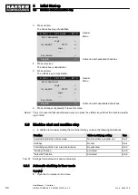
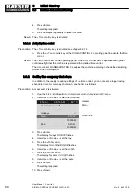
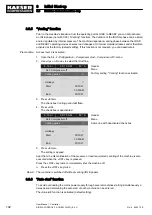
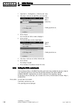

3. Press «Enter».
The setting mode is active.
4. Use «Up» or «Down» to set the
pA SP value.
5. Press «Enter».
The setting is applied.
6. Set the
SD switching differential in the same manner.
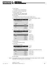
7. If necessary, adjust the value for the
pB SP and the SD switching differential in the same way.
8. Press «Escape» repeatedly to leave this menu.
Result The parameters for the network nominal pressure
pA and pB are set.
8.5.2.2 Setting the SD switching differential of the pressure increase
The pressure increase
pE SP primarily serves as a safety limit value for when the machine is exter‐
nally controlled. When the set pressure reaches the value
pE SP (for example, when the external
control does not function correctly) the machine switches to IDLE (not for SXC). The warning mes‐
sage
External load signal? is triggered.
The parameter for
pE SP pressure increase is pre-set and cannot be changed. You can, however,
adjust the
SD switching differential (not for SXC).
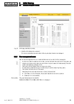
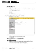
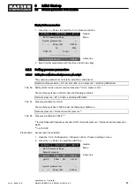
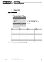
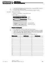
Displaying and adjusting the pressure increase parameters:
Pressure increase
Display parameters
Setting parameters
Switching point
pE SP
x
–
Switching differential
SD
x
x
x ≙ fitted, − ≙ not fitted
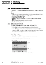
Tab. 59 Displaying and setting parameters
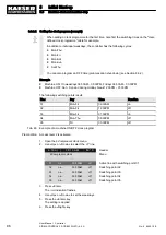
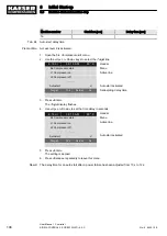
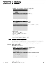
Precondition Access level 2 is activated.
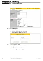
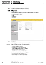
1. Open the 5.2.2
<Configuration – Pressure control – Pressure settings> menu.
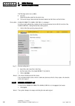
2. Use «Up» or «Down» to select the
pE SP line.
6 . 1 b a r
0 8 : 1 5 A M
8 0 ° C
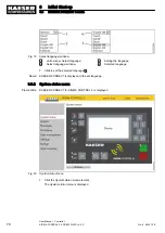
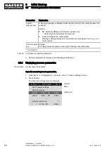
Header
5.2.2 Pressure settings
Menu
pRV:
16.0bar
------------------------------
Pressure rise
pE SP:
8.4bar ¦ SD:
−0.6bar
Active line
ΔpFC:
0.20bar
·········
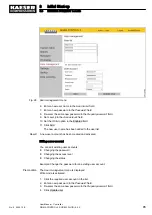
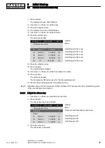
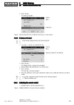
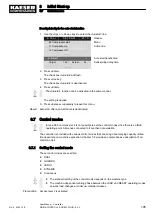
3. Press «Enter».
The setting mode is active.
4. Use «UP» or «DOWN» to set the required value for
SD.
5. Press «Enter».
The setting is applied.
6. Press «Escape» repeatedly to leave this menu.
8
Initial Start-up
8.5
Pressure parameters of the machine
92
User Manual Controller
SIGMA CONTROL 2 SCREW FLUID ≥5.0.X
No.: 9_9450 12 E


