OptoLyzer MOCCA Devices
© 2017 - 2018 K2L GmbH & Co. KG
23
DS60001526B
K2L USER MANUAL
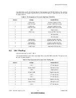
The table below is valid for both High-Speed CAN interfaces and CAN FD interfaces. The provided
GND pins must not be used unless there is no other GND connection. These pins must not be used
for supply purpose.
6.2 LIN / FlexRay
Connector type (see
The provided GND pin must not be used unless there is no other GND connection. This pin must not
be used for supply purpose.
Table 6.2 Pin Assignment of Connector High Speed CAN 2/4/6
PIN NO.
SIGNAL
DESCRIPTION
1
CAN 6-Low,
CAN FD 6-Low
Low-level CAN 6 bus line,
low-level CAN FD 6 bus line
2
CAN 2-Low,
CAN FD 2-Low
Low-level CAN 2 bus line,
low-level CAN FD 2 bus line
3
GND
Signal ground
4
CAN 4-Low
Low-level CAN 4 bus line
5
Not connected
6
Not connected
7
CAN 2-High,
CAN FD 2-High
High-level CAN 2 bus line,
high-level CAN FD 2 bus line
8
CAN 6-High,
CAN FD 6-High
High-level CAN 6 bus line,
high-level CAN FD 6 bus line
9
CAN 4-High
High-level CAN 4 bus line
Table 6.3 Pin Assignment of Connector LIN / FlexRay A/B
PIN NO.
SIGNAL
DESCRIPTION
1
LIN 3
3
rd
LIN channel
2
Channel B BP
Positive bus line
3
GND
Signal ground
4
Channel A BM
Negative bus line
5
LIN 4
4
th
LIN channel
6
LIN 5
5
th
LIN channel
7
Channel B BM
Negative bus line
8
Channel A BP
Positive bus line
9
LIN 6
6
th
LIN channel

