background image

8

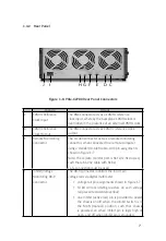
Feature

Details

G

Inhibit Switch

In the DEF (default) position, the front panel  power 

button turns the power supply on/off, and in the 

MAN (manual) position, the INHIBIT pin on the DB-9 

connector turns the power supply on/off

H

Fan Switch

In the HIGH position, fans operate at maximum speed, 

and in AUTO, the fans run based on the monitored 

chassis temperature

I

Universal Power Inlet 

Accepts IEC 60320-1 C19 power outletequipped 

connection

J

Chassis Ground Lug

The ground wire can be crimped to the ground lug, 

using a crimp tool of the appropriate size, with the 

other end connected to ground

Table  1-3: Rear Panel Legend

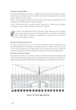
Figure 1-7: Inhibit/ Voltage & Remote Monitoring Connectors

Содержание PXIe-62780

Страница 1: ...PXIe 62780 18 slot PXI Express Chassis User s Manual Manual Rev 1 00 Revision Date Jul 15 2016...

Страница 2: ...201203 China Tel 86 21 5047 5899 Fax 86 21 5047 5899 Email service jytek com Additional information aids and tips that help users perform tasks Information to prevent minor physical injury component d...

Страница 3: ...2 3 2 Installing Peripheral Modules 18 2 4 Rack Mounting 20 2 4 1 Powering Up the System 21 3 System Management Configuration 22 3 1 Installing the Monitor Utility 22 3 2 Monitoring the PXIe 62780 23...

Страница 4: ...Rear Panel Legend 8 Table 1 4 PXI Star Trigger Line Assignment 11 Table 1 5 PXIe 62780 Reference Clock Priority 14 Table 2 1 Rack Mount Assembly Legend 20 Table 3 1 Supported Function Comparison Betwe...

Страница 5: ...8 PXIe 62780 Backplane 9 Figure 1 9 Temperature Sensors on Backplane 9 Figure 1 10 Star Trigger Routing 10 Figure 1 11 3U Hybrid Slot Compatible PXI 1 Peripheral Module 12 Figure 1 12 3U PXI Express P...

Страница 6: ...an innovative cooling scheme providing superior heat dissipation Three 185 9CFM fans in the rear section of the chassis draw cool air from apertures on the bottom and front of the chassis over the PXI...

Страница 7: ...Maximum Load Regulation Maximum Ripple Noise 5V 29 0 A 3 50 mV 12V 45 0 A 3 50 mV 3 3V 60 0 A 3 50 mV 12V 2 5 A 3 50 mV 10 MHz System Reference Clock 10 MHz REF Maximum clock skew between slots 300 ps...

Страница 8: ...oncondensing Functional shock 30 G half sine 11 ms pulse duration Random Vibration Operating 5 to 500 Hz 0 3 Grms 3 axes Nonoperating 5 to 500 Hz 2 46 Grms 3 axes Sound Pressure Level at operator posi...

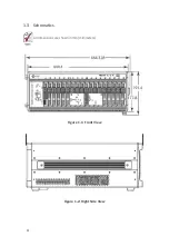
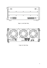
Страница 9: ...4 1 3 Schematics All dimensions are shown in mm millimeters Figure 1 1 Front View 465 3 Figure 1 2 Right Side View...

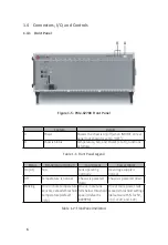
Страница 10: ...5 Figure 1 3 Left Side View Figure 1 4 Rear View...

Страница 11: ...ont Panel Legend Status Temperature Amber Fan Green Power Blue On Lit N A Fans operating normally DC voltage supply is normal Off Temperature is normal Chassis is powered down Chassis is powered down...

Страница 12: ...puter using a standard D sub9 cable with pin assignments shown in Figure 1 7 Note The remote monitor port is Rx Tx Tx Rx crossed such that a RS 232 cable with Rx Rx Tx Tx connection must be used F Inh...

Страница 13: ...In the HIGH position fans operate at maximum speed and in AUTO the fans run based on the monitored chassis temperature I Universal Power Inlet Accepts IEC 60320 1 C19 power outletequipped connection J...

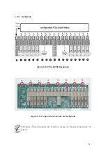
Страница 14: ...1 4 3 Backplane Figure 1 8 PXIe 62780 Backplane T1 T2 T3 T4 T5 T6 T7 T8 Figure 1 9 Temperature Sensors on Backplane For details of chassis temperature detection please see Chassis Temperature on page2...

Страница 15: ...ts and PXI Express Peripheral Slots comply with the default pin assignments as defined in PXI 5 PXI Express hardware specification Rev 1 0 PXI Express System Controller Slot The System Controller slot...

Страница 16: ...I Express x4 lanes peripheral slot if star trigger functionality is not required PXI Express Hybrid Peripheral Slots 10 PXI Express hybrid peripheral slots are provided in the PXIe 62780 all connected...

Страница 17: ...ripheral Module Figure 1 12 3U PXI Express Peripheral Module Local Bus The local bus on a PXI backplane is a daisy chained bus that connects each peripheral slot with adjacent peripheral slots to the...

Страница 18: ...taining 8 trigger lines connecting all slots on the same segment providing inter module synchronization PXI and PXI Express modules can exchange trigger or clock signals through the trigger bus allowi...

Страница 19: ...ce the external 10MHz clock input can override the onboard 10MHz clock source a phase lock loop PLL circuit on the backplane synchronizes the PXIe_ CLK100 and external 10MHz clock The PXIe 62780 PXI c...

Страница 20: ...ipping materials and carton in case you want to ship or store the product in the future Do not install or apply power to equipment that is damaged or missing components Retain the shipping carton and...

Страница 21: ...on 2 3 1 Installing the System Controller The PXIe 62780 incorporates a system controller slot supporting a PXI Express system controller of up to 4 slot width 1 Ensure the CPU memory module s and sto...

Страница 22: ...s with the cardguides and carefully slide the module into the chassis 5 Lift the latch until the module is securely seated in the chassis backplane 6 Fasten the screws on the module front panel and co...

Страница 23: ...ding a system timing module 1 Select an available peripheral slot 2 to 18 2 Depress the peripheral module s latch and align the module s top and bottom edges with the card guides 3 Carefully slide the...

Страница 24: ...the module s front panel 6 Repeat steps 1 to 5 to install additional PXI or PXIe peripheral modules To improve efficiency of heat dissipation after installing all PXI modules please install filler pl...

Страница 25: ...e 2 1 Rack Mount Assembly A Carrying Handle B 4 Rubber Feet only 2 shown C Mounting Brackets Table 2 1 Rack Mount Assembly Legend 1 Remove carrying handle from the right side 2 Remove the four rubber...

Страница 26: ...t voltage selection 1 Connect one end of the supplied power cord to thepower inlet located at the rear side of the chassis 2 Plug the other end of the AC power cord to a properly grounded wall socket...

Страница 27: ...tatus but does not provide the capability to change the trigger bus bridges and PCIe switch fabric settings Function comparison between the SMBus interface and RS 232 serial port is as follows Functio...

Страница 28: ...Control and Chassis Status Figure 3 1 PXIe 62780 Chassis Remote Mon Utility 3 2 1 Connect Control Interface Selects the communication interface between PXIe 62780 and utility Select Set to apply SMBus...

Страница 29: ...s available while Interface is set to RS232 Baud rate for RS232 is set to 9600 automatically for PXIe 62780 Chassis Status Log With the Chassis Status Log function monitored data can be recorded Selec...

Страница 30: ...Alarm Threshold Setting Provides operational and threshold settings for the PXIe 62780 including trigger bus PXIe link target temperature and fan mode and threshold settings for DC voltage temperature...

Страница 31: ...sed on the measured temperature Target Temp indicates the temperature at which fans run at 100 Using the default 50 C as an example fans run at 40 when all temperature readings are less than 25 C and...

Страница 32: ...n at full speed Selection of Auto or Full values and selecting Set directly changes cooling fan mode Alarm Threshold Displays Active alarm threshold settings including DC voltage temperature and fan s...

Страница 33: ...If the system fails to start when all installation conditions are met remove all installed peripheral modules and try again If the system starts normally install one peripheral module at a time follow...

Страница 34: ...of the chassis for superior portability and balance The PXIe 62780 weights 11 9 kg 26 2 lb Please be careful when moving the chassis to avoid any possible injury A 3 2 Cleaning the Exterior Make sure...

Страница 35: ...power source settings Always install and operate equipment near an easily accessible electrical socket outlet Secure the power cord do not place any object on over the power cord Only install attach a...

Отзывы: