4
2 Installation
2�1 Power Budget Consideration
Prior to installing any cards into the PXI-62700 chassis, please calculate the system power
requirement. The power budget for every DC power sources shall also be checked, including
+5V, +3.3V, +12V, -12V supply rail. Please refer to Appendix A for the maximum usable
power.
2�2 Step for Installation
Follow the step to power on the chassis.
Step 1: Make sure the power switch is in the OFF position.
Step 2: Plug in the AC power cord in each power supply unit.
Step 3: Install the controller. Please check the ejector/injector handle is pushed down.
Align the controller edge to the “RED” card guide, sliding in to the rear of the chassis.
Push up on the ejector/injector handle to fully inject the card into the chassis. Secure
the screws on the module’s front panel.
Step 4: Install peripheral modules if any.
Step 5: Press the power switch on the front panel to power on the chassis.
Step 6: Check the LED to make sure the power input is ready. There are four green LED
indicators of 3.3V, 5V, +12V, and -12V. The four LED will light when power turn on.
The fans should become operational as well.
Note: If the chassis does not power on, see Chapter 4, troubleshooting and Preventative
2�3 System Monitoring
There are LEDs on the front panel for system monitoring, including powers, temperature,
and fans. Please refer to following for the detailed meaning of display status on LEDs.
System Monitoring
• Power LED (Voltage : 3.3V, 5V, +12V, -12V)
◦
Color: Green
◦ ON while supplied
• Temperature LED
◦ Color: Amber
◦ ON for normal condition
◦ Flashes if exceeds temperature
•
Fan LED
Содержание PXI-62700
Страница 4: ...III Warranty Policy 26...
Страница 5: ...IV List of Tables Table 4 1 Troubleshooting 10...
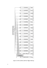
Страница 14: ...8 Figure 3 1 PXI Local Bus and Star Trigger Routing...


