


1-10 (No.MB422)
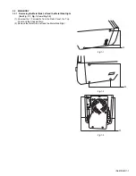
3.2.4 Removing the Cover Heat Sink and the Fan
(See Fig.4-1, Fig.4-2 and Fig.4-3)
(1) Unscrew the 5 Screws
E
from the Chassis Main and the
Rear Panel.
(2) Pulling out the cable connector from the AMP Board then
removing the Cover Heat Sink and the Fan.
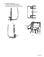
(3) Unscrew the 4 Screws
M
from the Fan.
(4) Removing the Fan.
Fig.4-1
Fig.4-2
Fig.4-3
E
E
E
E
E
CONNECTOR
M
Содержание UX-GD7
Страница 1: ......
Страница 35: ...2 1 Block diagram ...
Страница 37: ...2 3 Amp section ...
Страница 38: ...2 4 Function section ...
Страница 39: ...2 5 Video section ...
Страница 40: ...2 6 Micon section ...
Страница 41: ...2 7 Front section ...
Страница 43: ...2 9 Main board Lead free solder used in the board material Sn Ag Cu melting point 219 Centigrade Reverse side ...
Страница 45: ...2 11 Trans board Lead free solder used in the board material Sn Ag Cu melting point 219 Centigrade ...