11
n
Connections
n
Settings
When connecting
●
Turn OFF the power supply to all equipment to be used before making connections.
●
Carefully read the Instruction Manual for each piece of equipment to be used before
making connections.
●
For the appropriate connection cables and the length of these, carefully read “Connections
to Camera Terminal Board” on page 12.
●
The control signal cable cannot be used for loop connection.
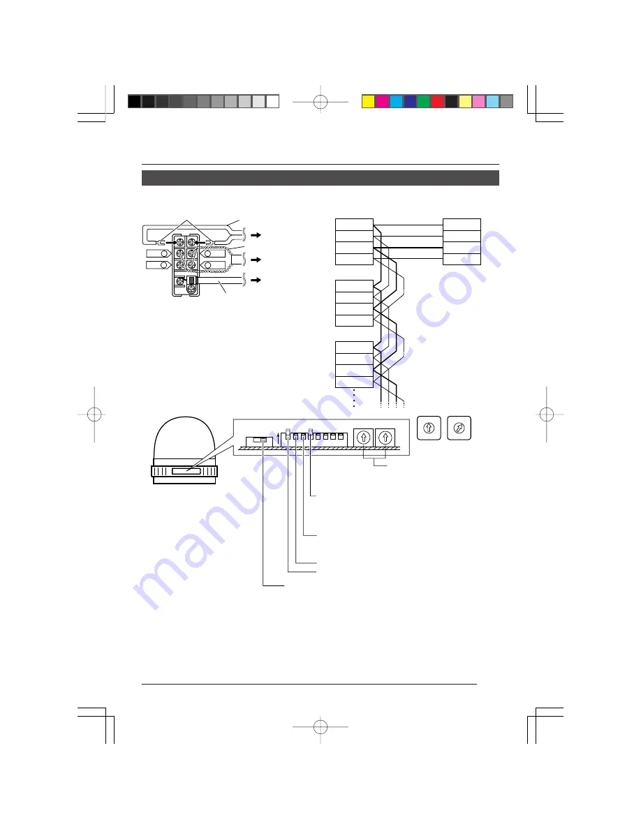
Lug plates
AC 24 V power cable
To AC 24V power
supply
To RM-P2580
To VIDEO INPUT
terminal on
RM-P2580
Connecting the control signal cable
(Use a twisted-pair cable for connection.
Z
See page 13.)
Camera 2
terminal board
Connect:
Camera TX+ to RM-P2580 RX+
Camera TX– to RM-P2580 RX–
Camera RX+ to RM-P2580 TX+
Camera RX– to RM-P2580 TX–
The
A
B
C
D
marks indicated
on both the camera terminals
and the RM-P2580 terminals
facilitate correct connections.
Connect the terminals with
identical marks.
C
TX
+
D
TX
–
A
RX
+
B
RX
–
TX
+
A
TX
–
B
RX
+
C
RX
–
D
TX
+
A
TX
–
B
RX
+
C
RX
–
D
TX
+
A
TX
–
B
RX
+
C
RX
–
D
RM-P2580
Camera 1
terminal board
Camera 3
terminal board
Control
signal cable
Video signal cable
(coaxial cable)
Terminal board
RX+ C
RX– D
A TX+
B TX–
1 2 3 4
ON
0
9
8
7
6
5
4
3
2
1
0
9
8
7
6
5
4
3
2
1
Camera ID setting switches
Set to match the RM-P2580 VIDEO
INPUT terminal number for each
camera.
Switch 3: Set this to ON (signal termination ON) only
on the camera placed at the end of the
control signal cable.
Set to OFF on all other cameras.
Switch 2: Set to OFF (DUPLEX) side.
Switch 1: Set to ON (MULTIDROP) side.
Control signal selector switch:
Set to the RS-422A/RS-485 side.
(Example: Camera 1
ID “
×
10” position 0,
ID “
×
1” position 1)
Switch 4: Select the synchronization method of the
camera image.
Set the switch on all cameras to ON (Line
Lock) and match with the V. PHASE.
(Only possible in 60 Hz regions.)
(
Z
See page 20.)
Содержание TK-AM200U - Active Movement Color Dome Camera
Страница 13: ......


