JVC KD-A77 A, Руководство по обслуживанию
Автомобильный магнитола JVC KD-A77 A - это инновационное устройство для вашего автомобиля. У нас вы можете бесплатно скачать сервисный мануал на русском языке для этой модели. Посетите manualshive.com и загрузите руководство по обслуживанию прямо сейчас.
Поделиться
Скачать


Отзывы:
Нет отзывов
Похожие инструкции для KD-A77 A

130
Бренд: Tascam Страницы: 2

700
Бренд: Nakamichi Страницы: 16
CR-2
Бренд: Nakamichi Страницы: 36
CR-2
Бренд: Nakamichi Страницы: 9
322
Бренд: Tascam Страницы: 5
6155
Бренд: NAD Страницы: 3
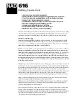
616
Бренд: NAD Страницы: 2
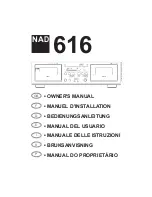
616
Бренд: NAD Страницы: 58

RQ-SW88V
Бренд: Panasonic Страницы: 2

RQ-CR18V
Бренд: Panasonic Страницы: 4

RQ-2102 - Cassette Recorder
Бренд: Panasonic Страницы: 7

RQ-SX47
Бренд: Panasonic Страницы: 4

RQ-SX53
Бренд: Panasonic Страницы: 3

RQ-SX47
Бренд: Panasonic Страницы: 2

RQ-CR15V
Бренд: Panasonic Страницы: 3

RQ-SX43
Бренд: Panasonic Страницы: 3

RQ-SX76
Бренд: Panasonic Страницы: 4

RQE20V - PERSONAL STEREO-LOW
Бренд: Panasonic Страницы: 10


