background image

36

SET UP menu

LT-32/26A61BU/SU / LCT1996-001A-U / English

4 Press the green or red button to 

search for a TV channel

Scanning stops when the TV finds a TV 
channel. Then the TV channel is 
displayed.

5 Press the green or red button 

repeatedly until the TV channel you 

want appears
If the TV channel reception is poor:

Press the blue or yellow button to fine-
tune the TV channel.

6 Press the 

a

 button and register 

the TV channel to a Programme 

number (PR)

The normal EDIT menu is resumed.

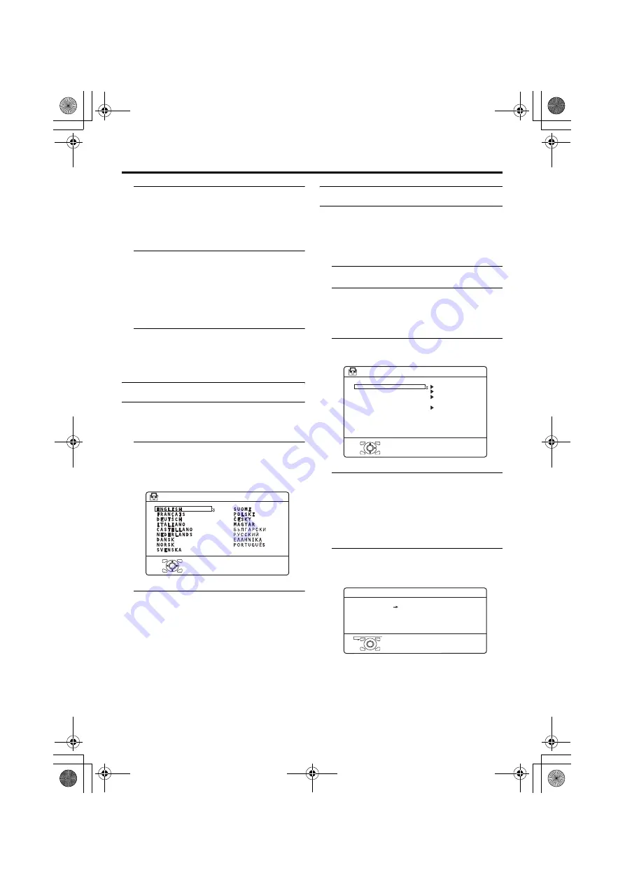
LANGUAGE

The LANGUAGE setting which was 

performed in the “Initial settings” (page 7) 
can be changed.

1 Choose LANGUAGE, then press 

the 

a

 or 

3

 button

A sub-menu of the LANGUAGE function 
appears.

2 Press the 

5

 and 

6

 buttons to 

choose a language. Then press the 

a

 button

DECODER (EXT-2)

If you have a decoder connected to a T-V 
LINK compatible VCR, which in turn is 

connected to the EXT-2 terminal, use the 
DECODER (EXT-2) function to unscramble 
the scrambled TV channels.

1 Turn on the decoder power

2 Display the scrambled TV channel 

on the TV

Even if the decoder is working, a 
scrambled picture appears.

3 Display the SET UP menu and 

choose DECODER (EXT-2)

4 Press the 

5

 buttons to choose 

ON

An unscrambled picture appears.

To cancel the DECODER (EXT-2) 

function:

Press the 

5

 buttons to choose OFF.

5 Press the 

a

 button to complete 

the setting

The T-V LINK menu appears.

You can send the programme numbers 
data to a VCR with the T-V LINK 
function.

D0002-EN

> LANGUAGE

OK

D0029

SET UP

AUTO PROGRAM
EDIT/MANUAL
LANGUAGE
DECODER(EXT-2)

OK

OFF

-EN

EXT SETTING

D0005

DOWNLOAD TV 

RECORDING DEVICE

T-V LINK

OK

EXIT

-EN

LT-32&26A61BUSU_Eng.book  Page 36  Tuesday, October 11, 2005  6:07 PM

Содержание InteriArt LT-26A61BU

Страница 1: ...ON YA369 2005 12 LT 26A61BJ LT 26A61BU LT 26A61BU C LT 26A61SJ LT 26A61SU LT 26A61SU C LT 32A61BJ LT 32A61BU LT 32A61BU C LT 32A61SJ LT 32A61SU LT 32A61SU C TABLE OF CONTENTS 1 PRECAUTION 1 3 2 SPECIFIC SERVICE INSTRUCTIONS 1 7 3 DISASSEMBLY 1 10 4 ADJUSTMENT 1 15 5 TROUBLESHOOTING 1 19 BASIC CHASSIS FT ...

Страница 2: ...ncy PAL SECAM NTSC 4 43MHz 4 40625MHz 4 25MHz 3 58MHz 4 43MHz LCD panel 26V inch wide aspect 16 9 32V inch wide aspect 16 9 Screen Size Diagonal 66 cm H 57 6 cm V 32 4 cm Diagonal 80 cm H 69 7 cm V 39 2 cm Display Pixels Horizontal 1366 dots Vertical 768 dots W XGA Audio Power Output 5 W 5 W Speaker 6 6 cm round type 2 Oblique corn Aerial terminal VHF UHF 75 Ω unbalanced coaxial EXT 1 EXT 2 Input ...

Страница 3: ...omponents that indicate evidence of overheating should be replaced Always use the manufacturer s replacement components 6 Isolation Check Safety for Electrical Shock Hazard After re assembling the product always perform an isolation check on the exposed metal parts of the cabinet antenna terminals video audio input and output terminals Control knobs metal cabinet screw heads earphone jack control ...

Страница 4: ...aracteristics are identified in the Parts List of Service Manual Electrical components having such features are identified by shading on the schematics and by on the Parts List in the Service Manual The use of a substitute replacement which does not have the same safety characteristics as the recommended replacement part shown in the Parts List of Service Manual may cause shock fire or other hazar...

Страница 5: ...ping in order to protect against accidents and earthquakes 1 3 3 INSTALLATION REQUIREMENTS To ensure safety in an emergency such as an earthquake and to prevent accidents ensure that measures are taken to prevent the TV dropping or falling over 1 3 4 NOTES ON HANDLING 1 WHEN TAKING UNIT OUT OF A PACKING CASE When taking the unit out of a packing case do not grasp the upper part of the unit If you ...

Страница 6: ...ring transportation and storage as the LCD panel is very vulnerable to lateral impacts and may break During transportation ensure that the unit is loaded along the traveling direction of the vehicle and avoid stacking them on one another For storage ensure that they are stacked in 2 layers or less even when placed upright 1 4 2 OPTICAL FILTER ON THE FRONT OF THE LCD PANEL 1 Avoid placing the unit ...

Страница 7: ...EL UNIT QLD0409 001 JUK QLD0371 001 JUK QLD0409 001 JUK MAIN PWB QAL0825 001 QAL0824 001 QAL0825 001 Pin No Signal designation Matching value EXT 1 EXT 2 1 AUDIO R output 500mV rms Nominal Low impedance Used TV OUT Used LINE OUT 2 AUDIO R input 500mV rms Nominal High impedance Used R1 Used R2 3 AUDIO L output 500mV rms Nominal Low impedance Used TV OUT Used LINE OUT 4 AUDIO GND Used Used 5 GND B U...

Страница 8: ...or 100 of each RGB colour and find out the cell that is flashing on and off BJ BU SJ and SU models AE is added to the serial No after at the Rating label BU C and SU C models CE is added to the serial No after at the Rating label Item Specifications 26V TYPE LCD PANEL UNIT 32V TYPE LCD PANEL UNIT QLD0370 002 JUK QLD0408 001 JUK QLD0371 001 JUK QLD0409 001 JUK Maximum dimensions W H D 626 mm 373 mm...

Страница 9: ... 26 P2 2 I key scan data 2 76 A14 O Program ROM address for CPU 27 P2 3 I Scaet1 ID H Detect 77 A12 O Program ROM address for CPU 28 NC1 Not used 78 A13 O Program ROM address for CPU 29 HS SSC I Horizontal sync 79 A7 O Program ROM address for CPU 30 VS I Vertical sync 80 FL_RST Test purpose 31 P3 0 O Data Read for Scaler IC 81 A8 O Program ROM address for CPU 32 P3 1 O Comunication for adjustment ...

Страница 10: ...OWER PWB 3 1 4 REMOVING THE MAIN PWB Remove the STAND Remove the REAR COVER Remove the TERMINAL BASE Remove the BACK BRACKET Remove the POWER PWB SHIELD 1 Remove the 7 screws M and 2 screws N then remove the MAIN PWB SHIELD 2 Remove the 6 screws P then remove the MAIN PWB 3 1 5 REMOVING THE KEY PWB Remove the STAND Remove the REAR COVER 1 Remove the 2 screws Q then remove the KEY PWB 3 1 6 REMOVIN...

Страница 11: ... PWB POWER CORD LCD PANEL UNIT CONTROL PWB KNOB BASE LED PWB FRONT PANEL TERMINAL BASE SPEAKER SPEAKER MAIN PWB D E J J M P G N H S T S P Q W U V V U K T J F R This exploded view shows the LT 32A61 series LT 26A61 series slightly differs from this exploded view however it can be disassembled in the same procedure as LT 26X506 B C A STAND ...

Страница 12: ...CTIONS and set the items as described 6 SERVICE MODE setting Verify what to set in the SERVICE MODE and set whatever is necessary Fig 1 Refer to the SERVICE ADJUSTMENT for setting 3 2 2 SERVICE MODE SETTING SERVICE MODE SCREEN NOTE As self check feature is not used in this TV 2 SELF_CHECK cannot be selected screen display only Fig 1 SETTING ITEM SERVICE MENU SERVICE MENU 1 ADJUST 1 ADJUST 2 SELF_C...

Страница 13: ...tion PICTURE MODE BRIGHT COLOUR TEMP COOL FEATURES DIGITAL VNR AUTO LOW COLOUR SYSTEM TV Depends on PR CH EXT AUTO 4 3 AUTO ASPECT PANORAMIC Setting item Setting position STEREO I II Stereo sound BASS Centre TREBLE Centre BALANCE Centre 3D SOUND OFF Setting item Setting position SLEEP TIMER OFF CHILD LOCK ID NO 0000 All CH off APPEARANCE TYPE D BLUE BACK ON FAVOURITE SETTING Reset Setting item Set...

Страница 14: ...he tweezers and remove the chip part Transistors diodes variable resistors etc 1 Apply extra solder to each lead 2 As shown in the figure push the part with tweezers and alternately melt the solder at each lead Shift and remove the chip part NOTE After removing the part remove remaining solder from the pattern 2 How to install Chip parts Resistors capacitors etc 1 Apply solder to the pattern as in...

Страница 15: ...ERATION OF SERVICE MODE 4 5 1 HOW TO ENTER THE SERVICE MODE 1 Press INFORMATION key and MUTING key on the remote control unit simultaneously to enter the SERVICE MODE SCREEN Fig 1 Fig 1 NOTE As self check feature is not used in this TV 2 SELF_CHECK cannot be selected screen display only Before entering the SERVICE MODE confirm that the setting of VCR TV DVD switch is at the TV side If the switches...

Страница 16: ...erature 5 SETTING ITEM NAME Setting item name are displayed The setting item numbers to be displayed are listed below 6 SETTING ITEM NO Setting item numbers are displayed For the setting item names to be displayed refer to INITIAL SETTING VALUES IN THE SERVICE MODE 7 SETTING VALUE DATA The SETTING VALUE is displayed 4 5 6 OPTION MODE Do not adjust Display of optin data setting 4 5 6 1 DESCRIPTION ...

Страница 17: ...26 HD CL G DR 32 31 00 S027 HD CL B DR 32 31 00 S028 HD WM R DR 32 31 00 S029 HD WM G DR 32 31 2 S030 HD WM B DR 32 31 1 S031 PC R OF 000 255 115 S032 PC G OF 000 255 127 S033 PC B OF 000 255 127 S034 PC R DR 32 31 23 S035 PC G DR 32 31 00 S036 PC B DR 32 31 00 S037 PC CL R DR 32 31 00 S038 PC CL G DR 32 31 03 S039 PC CL B DR 32 31 09 S040 PC WM R DR 32 31 00 S041 PC WM G DR 32 31 6 S042 PC WM B D...

Страница 18: ...6 5P B DR 00 63 30 SD07 HD75 R DR 00 63 30 SD08 HD75 G DR 00 63 26 SD09 HD75 B DR 00 63 30 SD10 HD25 R DR 00 63 30 SD11 HD25 G DR 00 63 26 SD12 HD25 B DR 00 63 30 SD13 PC R DR 00 63 5 SD14 PC G DR 00 63 5 SD15 PC B DR 00 63 5 Item No Item name Variable range Setting value Item No Item name Variable range Setting value DD07 5I S CON 00 63 31 DD08 5I S BRI 00 63 10 DD09 5I S SHA 00 63 35 DD10 5I S C...

Страница 19: ...IVE and S017 B DRIVE to setting values of left table 7 Adjust to Keep one of S030 Red drive S031 Green drive or S032 Blue drive unchanged then lower the other two so that the all white screen is equally white throughout NOTE Set one or more of S013 S015 and S017 to setting values of left table 8 Check that white balance is properly tracked from low light to high light If the white balance tracking...

Страница 20: ... No YA369 Flat Panel Display Category 12 3 chome Moriya cho Kanagawa ku Yokohama city Kanagawa prefecture 221 8528 Japan Victor Company of Japan Limited VPT Printed in Japan ...

Страница 21: ...LT 32 26A61BJ SJ LCT1999 001A U All Cover Cover01 WIDE LCD PANEL TV INSTRUCTIONS LT 32A61BJ LT 32A61SJ LT 26A61BJ LT 26A61SJ LT 32 26A61BJSJ_Eng book Page 1 Friday October 14 2005 1 40 PM ...

Страница 22: ...en to ensure optimal results and operational safety Before attempting to use this equipment read the operating instructions thoroughly Ensure that all electrical connections including the mains plug extension leads etc have been made in accordance with the manufacturer s instructions If ever in doubt about the installation operation or safety of this equipment consult your dealer Handle all glass ...

Страница 23: ... The TV screen may be damaged if the TV is carried as shown in the diagram below The TV should always be carried by two people Pixel defects LCDs use collections of fine points pixels to display images While there is no problem with more than 99 99 of these pixels please understand that a very small number of pixels may not light or may light all the time Distance recommendations Avoid improper in...

Страница 24: ... cannot be repaired may occur Pay attention to the following when handling the screen Do not use glue or adhesive tape on the screen Do not write on the screen Do not allow the screen to come in contact with any hard objects Do not allow condensation to form on the screen Do not use alcohol thinner benzene or other solvents on the screen Do not rub the screen hard The surface of the TV screen is e...

Страница 25: ...OM function 17 3D SOUND function 18 Return to TV channel instantly 18 Favourite channel function 19 Operating a JVC brand VCR or DVD player 20 Teletext function 21 Basic operation 21 Using the List Mode 21 Hold 22 Sub page 22 Reveal 22 Size 22 Index 23 Cancel 23 Using the TV s menu 24 Basic operation 24 PICTURE menu 25 PICTURE MODE 25 BRIGHT 1 25 CONTRAST 25 BRIGHT 2 25 SHARP 25 COLOUR 25 HUE 25 C...

Страница 26: ... generate a slight amount of heat during operation Ensure that sufficient space is available around the TV to allow satisfactory cooling See Distance recommendations on page 1 Using the stand This TV comes with a table top stand already attached This stand can be used to adjust the direction of the TV screen to the left or right Rotate the TV to the left and right While holding the bottom of the s...

Страница 27: ...r before connecting an antenna or VCR Leave the cover off if they do not fit properly Do not force to replace the cover Doing so may cause damage to the connection cables and the cover Remove the cover by removing the hooks When replacing the cover place the side of the cover against the TV and insert the hooks LT 32 26A61BJSJ_Eng book Page 5 Friday October 14 2005 1 40 PM ...

Страница 28: ...ed by a SCART cable C to the EXT 2 terminal on the TV For details about T V LINK functions see T V LINK functions on page 10 You can watch a video using the VCR without doing C For details see your VCR instruction manual To connect more equipment please see Connecting external equipment on page 40 If you connect a decoder to a T V LINK compatible VCR set the DECODER EXT 2 function to ON For detail...

Страница 29: ...upply are only for setting up and testing your TV please replace them as soon as you need to If the remote control does not work properly replace the batteries Initial settings When the TV is first turned on it goes into the initial settings mode and you will see the JVC logo Follow the instructions on the screen display to make the initial settings 1 Make sure to set the VCR TV DVD switch on the ...

Страница 30: ...M function The AUTO PROGRAM menu appears and received TV channels are automatically stored in the programme numbers PR To cancel the AUTO PROGRAM function Press the a button After the TV channels have been registered in the programme numbers PR the EDIT menu appears If you want to you can now edit the programme numbers PR using the EDIT MANUAL function For details see EDIT MANUAL on page 32 If you...

Страница 31: ...me number PR to which the TV channel has been set However which TV channels are set to which programme numbers PR will depend on the area in which you live If a TV channel you want to view is not set to a programme number PR you can set it using the MANUAL function For details see EDIT MANUAL on page 32 The AUTO PROGRAM function does not set the programme number PR 0 AV for your video cassette rec...

Страница 32: ...ected to the EXT 2 terminal Has the VCR power been turned on Does the SCART cable that is connected to the EXT 2 terminal to T V LINK compatible VCR have all its proper connections T V LINK functions When you have a T V LINK compatible VCR connected to the EXT 2 Terminal on the TV it is easier to set up the VCR and to view videos T V LINK uses the following features To use T V LINK functions A T V...

Страница 33: ...s changed or if the menu is displayed on the TV when recording images from an external device connected to the TV for example a camcorder when recording a TV channel after it has been unscrambled on a decoder when recording a TV channel by using the TV s output because the VCR s own tuner cannot properly receive that channel You cannot carry out Direct Rec using your TV s control Generally the VCR...

Страница 34: ... on from standby mode When the TV is turned on the power lamp lights blue To turn the TV off Press the A button again The power lamp goes off Caution The A button on the TV does not fully isolate the TV from the AC supply If you are not going to use the TV for a long period be sure to disconnect the AC plug from the AC socket Choose a TV channel Press the P p buttons to choose a programme number P...

Страница 35: ...English Adjust the volume Press the r Volume q buttons The volume level indicator appears Using the Menu Use the MENU OK button Refer to Using the TV s menu see page 24 for details of using the menu LT 32 26A61BJSJ_Eng book Page 13 Friday October 14 2005 1 40 PM ...

Страница 36: ...tons Turn the TV on or off from standby mode Press the standby button to turn the TV on or off When the TV is turned on the power lamp lights blue The power can be turned on by pressing the b button p p buttons or Number buttons 0 3 4 5 9 6 7 8 1 2 To turn the TV on or off set the VCR TV DVD switch on the remote control to the TV position and press the button If the VCR TV DVD switch on the remote...

Страница 37: ...of the original video source the motion may appear unnatural when the video source is input with progressive scanning component signals If this happens change the output setting of the connected device to interlace scanning component signal output See the instructions that came with the device for more information The PC sound is the same as the EXT 3 sound To return to a TV channel Press the b bu...

Страница 38: ...inal number is displayed Time display The current time of the teletext data is displayed If the TV has not received a TV channel that has teletext programmes since it was turned on the time display is blank To view the current time choose a TV channel that has teletext programmes An incorrect current time is sometimes displayed when watching videos PR LIST The programme number PR and EXT terminal ...

Страница 39: ...ight sides of a normal picture 4 3 aspect ratio to fill the screen without making the picture appear unnatural The top and bottom of the picture are slightly cut off 14 9 ZOOM This zooms up the wide picture 14 9 aspect ratio to the upper and lower limits of the screen 16 9 ZOOM This zooms up the wide picture 16 9 aspect ratio to the full screen 16 9 ZOOM SUBTITLE This zooms up the wide picture 16 ...

Страница 40: ...ned off on The ZOOM mode is changed g Text button is pressed The TV is switched between TV mode and EXT mode 3D SOUND function You can enjoy sounds with a wider ambience This function does not work for the sound from headphones Press the i button to select one of 3D SOUND modes ON When you listen to stereo sound please select ON mode You can enjoy sound similar to the experience at the theatre MON...

Страница 41: ...BLE appears on the screen Channels locked with the CHILD LOCK function cannot be registered If AUTO PROGRAM is performed the registered favourite channels are reset When you want to delete a favourite channel delete the set channel and set contents with FAVOURITE SETTING see page 31 in the FEATURES menu Calling the favourite channel 1 In the normal screen press the d favourite button Then FAVORITE...

Страница 42: ...e H or T button and display the DVD disc menu screen and then operate by pressing the 7 buttons 2 Press the VCR DVD Control Button to control your VCR or DVD player If your device is not made by JVC these buttons will not work Even if your device is made by JVC some of these buttons may not work depending on the device you are using You can use the p buttons to choose a TV channel the VCR will rec...

Страница 43: ...xt mode or Text mode You cannot operate menus when viewing a teletext programme Language display depends on the country which was set on the COUNTRY menu If characters on a Teletext programme do not appear properly change the COUNTRY setting to other country s To change the COUNTRY setting perform steps 1 and 2 of the AUTO PROGRAM procedure on page 32 and then press the a button Using the List Mod...

Страница 44: ...ved Press the C Hold button To cancel the Hold function Press C Hold button again Sub page Some teletext pages include sub pages that are automatically displayed You can hold any sub page or view it at any time 1 Press the d Favourite button to operate the Sub page function 2 Press the Number buttons to enter a sub page number Example 3rd sub page press 0 0 0 and 3 To cancel the Sub page function ...

Страница 45: ...to enter a page number or press a colour button The TV searches for a teletext page 2 Press H Cancel button The TV programme appears When the TV finds the teletext page its page number appears in the upper left of the screen 3 Press H Cancel button to return to a teletext page when the page number is on the screen The TV mode cannot be resumed by pressing the H Cancel button To return to the TV mo...

Страница 46: ...xit from the menu Some menu items may not be operated or set depending on the TV status or other menu item settings Menu items that cannot be operated or set are displayed in grey in the menu and cannot be chosen Types of menu The menu will disappear after about one minute if no operation is performed Operation with the buttons on the TV You can also operate the menus using the buttons on the fron...

Страница 47: ...trast and sharpness BRIGHT 1 You can adjust the back light 2 darker 3 brighter CONTRAST You can adjust the picture contrast 2 lower 3 higher BRIGHT 2 You can adjust the picture brightness 2 darker 3 brighter SHARP You can adjust the picture sharpness 2 softer 3 sharper COLOUR You can adjust the picture colour 2 lighter 3 deeper HUE You can adjust the picture tint 2 reddish 3 greenish You can chang...

Страница 48: ...e COLOUR SYSTEM Then press the a or 3 button The sub menu of the COLOUR SYSTEM function appears 2 Press the 6 buttons to choose the appropriate colour system Then press the a button PAL PAL system SECAM SECAM system NTSC 3 58 NTSC 3 58 MHz system NTSC 4 43 NTSC 4 43 MHz system AUTO This function detects a colour system from the input signal You can only use this when you are viewing a picture from...

Страница 49: ...modes REGULAR PANORAMIC or 14 9 ZOOM as the ZOOM mode for the normal picture 4 3 aspect ratio 1 Choose 4 3 AUTO ASPECT then press the a button 2 Press the 6 buttons to choose a ZOOM mode D0017 EN 4 3 AUTO ASPECT OK PANORAMIC REGULAR 14 9 ZOOM LT 32 26A61BJSJ_Eng book Page 27 Friday October 14 2005 1 40 PM ...

Страница 50: ... of the sound 2 weaker 3 strong TREBLE You can adjust the high tone of the sound 2 weaker 3 strong BALANCE You can adjust the volume balance between the left and right speaker 2 turn the left speaker s volume level up 3 turn the right speaker s volume level up 3D SOUND You can enjoy Surround sound with a live effect by using the 3D SOUND function You can choose a 3D SOUND mode from ON MONO and OFF...

Страница 51: ...ime to OFF CHILD LOCK When there is a TV channel you do not want your children to watch you can use the CHILD LOCK function to lock out the TV channel Even when a child chooses a programme number PR for a locked TV channel the screen will change to blue and display n CHILD LOCK so the TV channel cannot be viewed Unless you enter a pre set ID number by a special operation the lock cannot be release...

Страница 52: ...tten the ID number Perform step 1 of To set the CHILD LOCK function After confirming the ID number press the b button to exit the menu Even if you reset the lock temporarily it does not mean that the CHILD LOCK function set for the TV channel is cancelled The next time anyone tries to view the TV channel it will be locked again When you want to cancel the CHILD LOCK function you must perform the o...

Страница 53: ... The FAVOURITE SETTING menu appears 2 Press the 6 buttons and chose the favourite channel that you want to delete 3 Press the blue button The chosen favourite channel and set contents are deleted For details of the favourite channels see Favourite channel function on page 19 D0112 EN FAVOURITE SETTING OK RESET 1 PR 07 2 PR 01 3 PR 01 4 PR 01 LT 32 26A61BJSJ_Eng book Page 31 Friday October 14 2005 ...

Страница 54: ...e programme number PR of a TV channel ID This function registers a channel name ID to a TV channel INSERT This function adds a new TV channel in the current programme numbers PR list by using the CH CC number You cannot use the INSERT function if you do not know the channel number of a TV channel Use the MANUAL function to register a TV channel in the programme number PR DELETE This function delet...

Страница 55: ...amme number PR data For programme number PR 0 AV appears in the programme numbers PR list An EXT terminal number does not appear in the programme numbers PR list MOVE 1 Press the 6 buttons to choose a TV channel 2 Press the 3 button to start the MOVE function 3 Press the 6 buttons to choose a new programme number PR To cancel the MOVE function Press the b button 4 Press the 2 button to change the ...

Страница 56: ...1 and 2 of the AUTO PROGRAM page 32 procedure and set the COUNTRY setting to FRANCE before pressing the a button A CH CC number unique to this TV and corresponding to the Channel number of a TV channel is required Find the corresponding CH CC number from a table CH CC numbers on page 44 based on the Channel number of the TV channel When the COUNTRY setting is not FRANCE use a two digit CH CC numbe...

Страница 57: ... blue button to activate the MANUAL function At the right side following the CH CC number the SYSTEM broadcasting system of the TV channel appears To cancel the MANUAL function Press the b button 3 Press the 3 button to choose the SYSTEM broadcasting system for a TV channel you want to register TV channel SECAM L system from a French station Set the SYSTEM to L If it is set to one other than L you...

Страница 58: ...ge Then press the a button DECODER EXT 2 If you have a decoder connected to a T V LINK compatible VCR which in turn is connected to the EXT 2 terminal use the DECODER EXT 2 function to unscramble the scrambled TV channels 1 Turn on the decoder power 2 Display the scrambled TV channel on the TV Even if the decoder is working a scrambled picture appears 3 Display the SET UP menu and choose DECODER E...

Страница 59: ...r 3 button The EXT SETTING menu appears 2 Follow the instructions for the function you want to use and operate the function S IN You can enjoy the high quality picture of the S VIDEO signal Y C signal DUBBING You can choose a signal source to be output from an EXT 2 terminal S IN S VIDEO input You can connect a device such as an S VHS VCR to enjoy the high quality picture of the S VIDEO signal Y C...

Страница 60: ...output from the EXT 2 terminal You can do this with the output signals of the devices connected to other EXT terminals or with the picture and sound from a TV channel you are currently viewing 1 Press the 5 buttons to choose the arrow from the menu 2 Press the 6 buttons to choose an EXT terminal or TV Then press the a button The arrow in the menu represents a signal flow The left side of the arrow...

Страница 61: ...n you choose an EXT terminal as an output you can view a TV programme or a picture from the other EXT terminal while dubbing the picture from a device connected to the EXT terminal onto a VCR connected to the EXT 2 terminal The RGB signals from TV games cannot be output Teletext programmes cannot be output LT 32 26A61BJSJ_Eng book Page 39 Friday October 14 2005 1 40 PM ...

Страница 62: ...onnecting equipment not listed in the following connection diagram see the table to choose the best EXT terminal Connecting cables are not supplied 1 VCR composite signal 2 VCR composite signal S VIDEO signal 3 T V LINK compatible VCR composite signal S VIDEO signal 4 Decoder 5 DVD player composite signal S VIDEO signal 6 DVD player composite signal RGB signal 7 DVD player component video signals ...

Страница 63: ...Additional preparation 41 LT 32 26A61BJ SJ LCT1999 001A U English without terminal covers LT 32 26A61BJSJ_Eng book Page 41 Friday October 14 2005 1 40 PM ...

Страница 64: ... when you want to dub the video sound from another device onto the VCR connected to the EXT 2 terminal For details on how to do this see DUBBING on page 38 The signals from EXT 4 and PC IN terminal cannot be output from EXT 2 TV output from the EXT 1 terminal The video sound signal of a TV channel you are viewing is always output from the EXT 1 terminal Changing over a programme number PR also cha...

Страница 65: ...put from HDMI compatible device to the VIDEO 3 AUDIO L R terminal on the back of the TV To watch the images from a HDMI DVI compatible device press the G or p p buttons to choose DVI To connect the DVI compatible device to the DVI terminal connect the DVI terminal of the DVI compatible device to the DVI terminal of the TV with the DVI cable Ensure that the connectors are facing the correct way whe...

Страница 66: ... S12 CC 13 CC 213 S13 CC 14 CC 214 S14 CC 15 CC 215 S15 CC 16 CC 216 S16 CC 17 CC 217 S17 CC 18 CC 218 S18 CC 19 CC 219 S19 CC 20 CC 220 S20 CC 21 CC 221 S21 CC 22 CC 222 S22 CC 23 CC 223 S23 CC 24 CC 224 S24 CC 25 CC 225 S25 CC 26 CC 226 S26 CC 27 CC 227 S27 CC 28 CC 228 S28 CC 29 CC 229 S29 CC 30 CC 230 S30 CC Channel CC 31 CC 231 S31 CC 32 CC 232 S32 CC 33 CC 233 S33 CC 34 CC 234 S34 CC 35 CC 2...

Страница 67: ...e CH CC number CC110 to CC161 corresponding to the TV channel SECAM L system from a French cable TV station based on the broadcast frequency of the TV channel When you do not know the broadcast frequency please contact the cable TV station The CH CC numbers of CH102 CH169 and CC110 CC161 correspond to the TV channels being broadcast by a SECAM L system The other CH CC numbers correspond to the TV ...

Страница 68: ...d is muted If you still want to view the TV channel follow the description BLUE BACK on page 30 to change the BLUE BACK function setting to OFF If the SYSTEM setting for a TV channel is incorrect it may prevent the sound from being issued Follow the description EDIT MANUAL on page 32 to use the MANUAL function to try to change the SYSTEM setting When you are using EXT 3 EXT 4 or DVI terminal make ...

Страница 69: ...te control from the sides or rear of the TV or from more than seven metres away from the TV Use the remote control in front of your TV or from less than seven metres away When you are viewing a teletext programme you cannot operate the menus Press the b button to return to the ordinary TV programme and then try operating the menus If the TV suddenly stops responding disconnect the power cord of th...

Страница 70: ...le the screen may become white for a moment This happens when the signal which drives the liquid crystal is missing This is not a fault When a still image has been displayed for a long period a faint residual image may remain on the screen for a short time after the power has been turned off or when another image is displayed This is not a fault and the image will eventually disappear LT 32 26A61B...

Страница 71: ...49 LT 32 26A61BJ SJ LCT1999 001A U English Cable management 1 2 3 4 LT 32 26A61BJSJ_Eng book Page 49 Friday October 14 2005 1 40 PM ...

Страница 72: ... output Rated Power output 5 W 5 W Speakers 6 6 cm round 2 EXT 1 terminal Euroconnector 21 pin SCART Video input Audio L R inputs and RGB inputs are available TV broadcast outputs Video and Audio L R are available EXT 2 terminal Euroconnector 21 pin SCART Video input S VIDEO Y C input Audio L R inputs and RGB inputs are available Video and Audio L R outputs are available T V LINK functions are ava...

Страница 73: ...UCTIONS BREEDBEELD LCD TV GEBRUIKSAANWIJZING TELEVISOR CON PANEL LCD PANORÁMICO MANUAL DE INSTRUCCIONES TV LCD WIDESCREEN ISTRUZIONI TELEVISOR COM ECRÃ PANORÂMICO DE CRISTAL LÍQUIDO INSTRUÇÕES LT 32A61BU LT 32A61SU LT 26A61BU LT 26A61SU ENGLISH DEUTSCH FRANÇAIS NEDERLANDS CASTELLANO ITALIANO PORTUGUÊS LCT1996 001A U_Cover fm Page 1 Friday October 7 2005 2 07 PM ...

Страница 74: ...ION The TV screen may be damaged if the TV is carried as shown in the diagram below The TV should always be carried by two people Pixel defects LCDs use collections of fine points pixels to display images While there is no problem with more than 99 99 of these pixels please understand that a very small number of pixels may not light or may light all the time Distance recommendations Avoid improper...

Страница 75: ... cannot be repaired may occur Pay attention to the following when handling the screen Do not use glue or adhesive tape on the screen Do not write on the screen Do not allow the screen to come in contact with any hard objects Do not allow condensation to form on the screen Do not use alcohol thinner benzene or other solvents on the screen Do not rub the screen hard The surface of the TV screen is e...

Страница 76: ...n 16 ZOOM function 17 3D SOUND function 18 Return to TV channel instantly 18 Favourite channel function 19 Operating a JVC brand VCR or DVD player 20 Teletext function 21 Basic operation 21 Using the List Mode 21 Hold 22 Sub page 22 Reveal 22 Size 22 Index 23 Cancel 23 Using the TV s menu 24 Basic operation 24 PICTURE menu 25 PICTURE MODE 25 BRIGHT 1 25 CONTRAST 25 BRIGHT 2 25 SHARP 25 COLOUR 25 H...

Страница 77: ...generate a slight amount of heat during operation Ensure that sufficient space is available around the TV to allow satisfactory cooling See Distance recommendations on page 1 Using the stand This TV comes with a table top stand already attached This stand can be used to adjust the direction of the TV screen to the left or right Rotate the TV to the left and right While holding the bottom of the st...

Страница 78: ...cover before connecting an antenna or VCR Leave the cover off if they do not fit properly Do not force to replace the cover Doing so may cause damage to the connection cables and the cover Remove the cover by removing the hooks When replacing the cover place the side of the cover against the TV and insert the hooks LT 32 26A61BUSU_Eng book Page 5 Tuesday October 11 2005 6 07 PM ...

Страница 79: ...ed by a SCART cable C to the EXT 2 terminal on the TV For details about T V LINK functions see T V LINK functions on page 10 You can watch a video using the VCR without doing C For details see your VCR instruction manual To connect more equipment please see Connecting external equipment on page 40 If you connect a decoder to a T V LINK compatible VCR set the DECODER EXT 2 function to ON For detail...

Страница 80: ...we supply are only for setting up and testing your TV please replace them as soon as you need to If the remote control does not work properly replace the batteries Initial settings When the TV is first turned on it goes into the initial settings mode and you will see the JVC logo Follow the instructions on the screen display to make the initial settings 1 Make sure to set the VCR TV DVD switch on ...

Страница 81: ...here you are 6 Press the blue button to start the AUTO PROGRAM function The AUTO PROGRAM menu appears and received TV channels are automatically stored in the programme numbers PR To cancel the AUTO PROGRAM function Press the a button After the TV channels have been registered in the programme numbers PR the EDIT menu appears If you want to you can now edit the programme numbers PR using the EDIT ...

Страница 82: ...our TV can detect the TV channel name from the TV channel broadcast signal the TV channel name is assigned to the programme number PR to which the TV channel has been set However which TV channels are set to which programme numbers PR will depend on the area in which you live If a TV channel you want to view is not set to a programme number PR you can set it using the MANUAL function For details s...

Страница 83: ...cted to the EXT 2 terminal Has the VCR power been turned on Does the SCART cable that is connected to the EXT 2 terminal to T V LINK compatible VCR have all its proper connections T V LINK functions When you have a T V LINK compatible VCR connected to the EXT 2 Terminal on the TV it is easier to set up the VCR and to view videos T V LINK uses the following features To use T V LINK functions A T V ...

Страница 84: ...ut is changed or if the menu is displayed on the TV when recording images from an external device connected to the TV for example a camcorder when recording a TV channel after it has been unscrambled on a decoder when recording a TV channel by using the TV s output because the VCR s own tuner cannot properly receive that channel You cannot carry out Direct Rec using your TV s control Generally the...

Страница 85: ...he TV on from standby mode When the TV is turned on the power lamp lights blue To turn the TV off Press the A button again The power lamp goes off Caution The A button on the TV does not fully isolate the TV from the AC supply If you are not going to use the TV for a long period be sure to disconnect the AC plug from the AC socket Choose a TV channel Press the P p buttons to choose a programme num...

Страница 86: ... U English Adjust the volume Press the r Volume q buttons The volume level indicator appears Using the Menu Use the MENU OK button Refer to Using the TV s menu see page 24 for details of using the menu LT 32 26A61BUSU_Eng book Page 13 Tuesday October 11 2005 6 07 PM ...

Страница 87: ...ons Turn the TV on or off from standby mode Press the standby button to turn the TV on or off When the TV is turned on the power lamp lights blue The power can be turned on by pressing the b button p p buttons or Number buttons 0 3 4 5 9 6 7 8 1 2 To turn the TV on or off set the VCR TV DVD switch on the remote control to the TV position and press the button If the VCR TV DVD switch on the remote ...

Страница 88: ...on of the original video source the motion may appear unnatural when the video source is input with progressive scanning component signals If this happens change the output setting of the connected device to interlace scanning component signal output See the instructions that came with the device for more information The PC sound is the same as the EXT 3 sound To return to a TV channel Press the b...

Страница 89: ...nal number is displayed Time display The current time of the teletext data is displayed If the TV has not received a TV channel that has teletext programmes since it was turned on the time display is blank To view the current time choose a TV channel that has teletext programmes An incorrect current time is sometimes displayed when watching videos PR LIST The programme number PR and EXT terminal l...

Страница 90: ...d right sides of a normal picture 4 3 aspect ratio to fill the screen without making the picture appear unnatural The top and bottom of the picture are slightly cut off 14 9 ZOOM This zooms up the wide picture 14 9 aspect ratio to the upper and lower limits of the screen 16 9 ZOOM This zooms up the wide picture 16 9 aspect ratio to the full screen 16 9 ZOOM SUBTITLE This zooms up the wide picture ...

Страница 91: ...ned off on The ZOOM mode is changed g Text button is pressed The TV is switched between TV mode and EXT mode 3D SOUND function You can enjoy sounds with a wider ambience This function does not work for the sound from headphones Press the i button to select one of 3D SOUND modes ON When you listen to stereo sound please select ON mode You can enjoy sound similar to the experience at the theatre MON...

Страница 92: ...AILABLE appears on the screen Channels locked with the CHILD LOCK function cannot be registered If AUTO PROGRAM is performed the registered favourite channels are reset When you want to delete a favourite channel delete the set channel and set contents with FAVOURITE SETTING see page 31 in the FEATURES menu Calling the favourite channel 1 In the normal screen press the d favourite button Then FAVO...

Страница 93: ... H or T button and display the DVD disc menu screen and then operate by pressing the 7 buttons 2 Press the VCR DVD Control Button to control your VCR or DVD player If your device is not made by JVC these buttons will not work Even if your device is made by JVC some of these buttons may not work depending on the device you are using You can use the p buttons to choose a TV channel the VCR will rece...

Страница 94: ... text mode or Text mode You cannot operate menus when viewing a teletext programme Language display depends on the country which was set on the COUNTRY menu If characters on a Teletext programme do not appear properly change the COUNTRY setting to other country s To change the COUNTRY setting perform steps 1 and 2 of the AUTO PROGRAM procedure on page 32 and then press the a button Using the List ...

Страница 95: ...ed Press the C Hold button To cancel the Hold function Press C Hold button again Sub page Some teletext pages include sub pages that are automatically displayed You can hold any sub page or view it at any time 1 Press the d Favourite button to operate the Sub page function 2 Press the Number buttons to enter a sub page number Example 3rd sub page press 0 0 0 and 3 To cancel the Sub page function P...

Страница 96: ...on to enter a page number or press a colour button The TV searches for a teletext page 2 Press H Cancel button The TV programme appears When the TV finds the teletext page its page number appears in the upper left of the screen 3 Press H Cancel button to return to a teletext page when the page number is on the screen The TV mode cannot be resumed by pressing the H Cancel button To return to the TV...

Страница 97: ...xit from the menu Some menu items may not be operated or set depending on the TV status or other menu item settings Menu items that cannot be operated or set are displayed in grey in the menu and cannot be chosen Types of menu The menu will disappear after about one minute if no operation is performed Operation with the buttons on the TV You can also operate the menus using the buttons on the fron...

Страница 98: ... contrast and sharpness BRIGHT 1 You can adjust the back light 2 darker 3 brighter CONTRAST You can adjust the picture contrast 2 lower 3 higher BRIGHT 2 You can adjust the picture brightness 2 darker 3 brighter SHARP You can adjust the picture sharpness 2 softer 3 sharper COLOUR You can adjust the picture colour 2 lighter 3 deeper HUE You can adjust the picture tint 2 reddish 3 greenish You can c...

Страница 99: ...e COLOUR SYSTEM Then press the a or 3 button The sub menu of the COLOUR SYSTEM function appears 2 Press the 6 buttons to choose the appropriate colour system Then press the a button PAL PAL system SECAM SECAM system NTSC 3 58 NTSC 3 58 MHz system NTSC 4 43 NTSC 4 43 MHz system AUTO This function detects a colour system from the input signal You can only use this when you are viewing a picture from...

Страница 100: ...OOM modes REGULAR PANORAMIC or 14 9 ZOOM as the ZOOM mode for the normal picture 4 3 aspect ratio 1 Choose 4 3 AUTO ASPECT then press the a button 2 Press the 6 buttons to choose a ZOOM mode D0017 EN 4 3 AUTO ASPECT OK PANORAMIC REGULAR 14 9 ZOOM LT 32 26A61BUSU_Eng book Page 27 Tuesday October 11 2005 6 07 PM ...

Страница 101: ...of the sound 2 weaker 3 strong TREBLE You can adjust the high tone of the sound 2 weaker 3 strong BALANCE You can adjust the volume balance between the left and right speaker 2 turn the left speaker s volume level up 3 turn the right speaker s volume level up 3D SOUND You can enjoy Surround sound with a live effect by using the 3D SOUND function You can choose a 3D SOUND mode from ON MONO and OFF ...

Страница 102: ...f time to OFF CHILD LOCK When there is a TV channel you do not want your children to watch you can use the CHILD LOCK function to lock out the TV channel Even when a child chooses a programme number PR for a locked TV channel the screen will change to blue and display n CHILD LOCK so the TV channel cannot be viewed Unless you enter a pre set ID number by a special operation the lock cannot be rele...

Страница 103: ...ten the ID number Perform step 1 of To set the CHILD LOCK function After confirming the ID number press the b button to exit the menu Even if you reset the lock temporarily it does not mean that the CHILD LOCK function set for the TV channel is cancelled The next time anyone tries to view the TV channel it will be locked again When you want to cancel the CHILD LOCK function you must perform the op...

Страница 104: ...tton The FAVOURITE SETTING menu appears 2 Press the 6 buttons and chose the favourite channel that you want to delete 3 Press the blue button The chosen favourite channel and set contents are deleted For details of the favourite channels see Favourite channel function on page 19 D0112 EN FAVOURITE SETTING OK RESET 1 PR 07 2 PR 01 3 PR 01 4 PR 01 LT 32 26A61BUSU_Eng book Page 31 Tuesday October 11 ...

Страница 105: ... programme number PR of a TV channel ID This function registers a channel name ID to a TV channel INSERT This function adds a new TV channel in the current programme numbers PR list by using the CH CC number You cannot use the INSERT function if you do not know the channel number of a TV channel Use the MANUAL function to register a TV channel in the programme number PR DELETE This function delete...

Страница 106: ...rogramme number PR data For programme number PR 0 AV appears in the programme numbers PR list An EXT terminal number does not appear in the programme numbers PR list MOVE 1 Press the 6 buttons to choose a TV channel 2 Press the 3 button to start the MOVE function 3 Press the 6 buttons to choose a new programme number PR To cancel the MOVE function Press the b button 4 Press the 2 button to change ...

Страница 107: ... and 2 of the AUTO PROGRAM page 32 procedure and set the COUNTRY setting to FRANCE before pressing the a button A CH CC number unique to this TV and corresponding to the Channel number of a TV channel is required Find the corresponding CH CC number from a table CH CC numbers on page 44 based on the Channel number of the TV channel When the COUNTRY setting is not FRANCE use a two digit CH CC number...

Страница 108: ...the blue button to activate the MANUAL function At the right side following the CH CC number the SYSTEM broadcasting system of the TV channel appears To cancel the MANUAL function Press the b button 3 Press the 3 button to choose the SYSTEM broadcasting system for a TV channel you want to register TV channel SECAM L system from a French station Set the SYSTEM to L If it is set to one other than L ...

Страница 109: ...e Then press the a button DECODER EXT 2 If you have a decoder connected to a T V LINK compatible VCR which in turn is connected to the EXT 2 terminal use the DECODER EXT 2 function to unscramble the scrambled TV channels 1 Turn on the decoder power 2 Display the scrambled TV channel on the TV Even if the decoder is working a scrambled picture appears 3 Display the SET UP menu and choose DECODER EX...

Страница 110: ... a or 3 button The EXT SETTING menu appears 2 Follow the instructions for the function you want to use and operate the function S IN You can enjoy the high quality picture of the S VIDEO signal Y C signal DUBBING You can choose a signal source to be output from an EXT 2 terminal S IN S VIDEO input You can connect a device such as an S VHS VCR to enjoy the high quality picture of the S VIDEO signal...

Страница 111: ...utput from the EXT 2 terminal You can do this with the output signals of the devices connected to other EXT terminals or with the picture and sound from a TV channel you are currently viewing 1 Press the 5 buttons to choose the arrow from the menu 2 Press the 6 buttons to choose an EXT terminal or TV Then press the a button The arrow in the menu represents a signal flow The left side of the arrow ...

Страница 112: ...When you choose an EXT terminal as an output you can view a TV programme or a picture from the other EXT terminal while dubbing the picture from a device connected to the EXT terminal onto a VCR connected to the EXT 2 terminal The RGB signals from TV games cannot be output Teletext programmes cannot be output LT 32 26A61BUSU_Eng book Page 39 Tuesday October 11 2005 6 07 PM ...

Страница 113: ...necting equipment not listed in the following connection diagram see the table to choose the best EXT terminal Connecting cables are not supplied 1 VCR composite signal 2 VCR composite signal S VIDEO signal 3 T V LINK compatible VCR composite signal S VIDEO signal 4 Decoder 5 DVD player composite signal S VIDEO signal 6 DVD player composite signal RGB signal 7 DVD player component video signals Y ...

Страница 114: ...Additional preparation 41 ENGLISH LT 32 26A61BU SU LCT1996 001A U English without terminal covers LT 32 26A61BUSU_Eng book Page 41 Tuesday October 11 2005 6 07 PM ...

Страница 115: ... when you want to dub the video sound from another device onto the VCR connected to the EXT 2 terminal For details on how to do this see DUBBING on page 38 The signals from EXT 4 and PC IN terminal cannot be output from EXT 2 TV output from the EXT 1 terminal The video sound signal of a TV channel you are viewing is always output from the EXT 1 terminal Changing over a programme number PR also cha...

Страница 116: ...output from HDMI compatible device to the VIDEO 3 AUDIO L R terminal on the back of the TV To watch the images from a HDMI DVI compatible device press the G or p p buttons to choose DVI To connect the DVI compatible device to the DVI terminal connect the DVI terminal of the DVI compatible device to the DVI terminal of the TV with the DVI cable Ensure that the connectors are facing the correct way ...

Страница 117: ... S12 CC 13 CC 213 S13 CC 14 CC 214 S14 CC 15 CC 215 S15 CC 16 CC 216 S16 CC 17 CC 217 S17 CC 18 CC 218 S18 CC 19 CC 219 S19 CC 20 CC 220 S20 CC 21 CC 221 S21 CC 22 CC 222 S22 CC 23 CC 223 S23 CC 24 CC 224 S24 CC 25 CC 225 S25 CC 26 CC 226 S26 CC 27 CC 227 S27 CC 28 CC 228 S28 CC 29 CC 229 S29 CC 30 CC 230 S30 CC Channel CC 31 CC 231 S31 CC 32 CC 232 S32 CC 33 CC 233 S33 CC 34 CC 234 S34 CC 35 CC 2...

Страница 118: ... the CH CC number CC110 to CC161 corresponding to the TV channel SECAM L system from a French cable TV station based on the broadcast frequency of the TV channel When you do not know the broadcast frequency please contact the cable TV station The CH CC numbers of CH102 CH169 and CC110 CC161 correspond to the TV channels being broadcast by a SECAM L system The other CH CC numbers correspond to the ...

Страница 119: ...d is muted If you still want to view the TV channel follow the description BLUE BACK on page 30 to change the BLUE BACK function setting to OFF If the SYSTEM setting for a TV channel is incorrect it may prevent the sound from being issued Follow the description EDIT MANUAL on page 32 to use the MANUAL function to try to change the SYSTEM setting When you are using EXT 3 EXT 4 or DVI terminal make ...

Страница 120: ... the remote control from the sides or rear of the TV or from more than seven metres away from the TV Use the remote control in front of your TV or from less than seven metres away When you are viewing a teletext programme you cannot operate the menus Press the b button to return to the ordinary TV programme and then try operating the menus If the TV suddenly stops responding disconnect the power c...

Страница 121: ...e the screen may become white for a moment This happens when the signal which drives the liquid crystal is missing This is not a fault When a still image has been displayed for a long period a faint residual image may remain on the screen for a short time after the power has been turned off or when another image is displayed This is not a fault and the image will eventually disappear LT 32 26A61BU...

Страница 122: ...49 ENGLISH LT 32 26A61BU SU LCT1996 001A U English Cable management 1 2 3 4 LT 32 26A61BUSU_Eng book Page 49 Tuesday October 11 2005 6 07 PM ...

Страница 123: ...ed Power output 5 W 5 W Speakers 6 6 cm round 2 EXT 1 terminal Euroconnector 21 pin SCART Video input Audio L R inputs and RGB inputs are available TV broadcast outputs Video and Audio L R are available EXT 2 terminal Euroconnector 21 pin SCART Video input S VIDEO Y C input Audio L R inputs and RGB inputs are available Video and Audio L R outputs are available T V LINK functions are available EXT ...

Страница 124: ... 2005 Victor Company of Japan Limited LT 32 26A61BU SU LCT1996 001A U All Cover Cover04 LCT1996 001A U 1005TKH CR MU LCT1996 001A U_Cover fm Page 6 Friday October 7 2005 2 07 PM ...

Страница 125: ... YA369 2005 12 WIDE LCD PANEL TELEVISION YA369 2005 12 LT 26A61BJ LT 26A61BU LT 26A61BU C LT 26A61SJ LT 26A61SU LT 26A61SU C LT 32A61BJ LT 32A61BU LT 32A61BU C LT 32A61SJ LT 32A61SU LT 32A61SU C BASIC CHASSIS FT CD ROM No SML200512 SCHEMATIC DIAGRAMS ...

Страница 126: ...lene capacitor MPP Metalized polypropylene capacitor MF Metalized film capacitor TF Thin film capacitor BP Bipolar electrolytic capacitor TAN Tantalum capacitor 3 Coils No unit Others µH As specified No indication Ceramic capacitor 2 Capacitors Capacitance value 1 or higher pF less than 1 µF Withstand voltage No indication DC50 V Others DC withstand voltage V AC indicated AC withstand voltage V El...

Страница 127: ...W BOARD POWER P W BOARD LED P W BOARD KEY P W BOARD QAL0823 001 QAL0826 001 QAL0827 001 QAL0828 001 LT 26A61BJ QAL0822 001 LT 26A61BU QAL0823 001 LT 26A61BU C LT 26A61SJ LT 26A61SU LT 26A61SU C P W B ASS Y name MAIN P W BOARD POWER P W BOARD LED P W BOARD KEY P W BOARD QAL0825 001 QAL0826 001 QAL0827 001 QAL0828 001 LT 32A61BJ QAL0824 001 LT 32A61BU QAL0825 001 LT 32A61BU C LT 32A61SJ LT 32A61SU L...

Страница 128: ...ANEL UNIT POWER CORD WIRING DIAGRAM CN2 CN1 CN3 LCD PANEL UNIT LCD PANEL UNIT POWER PWB J602 J501 J304 J210 J209 J801 J601 MAIN PWB SPEAKER R SPEAKER L H701 U V TUNER J210 1 4 1 LED PWB TOP TOP J209 1 7 1 KEY PWB 10 1 15 4 7 1 1 30 1 1 2 1 3 4 1 1 15 1 ...

Страница 129: ...T 2 J204 J205 EXT 3 S VIDEO VIDEO AUDIO L R J205 EXT 4 Y Pb Pr DACM_R L OUT2 OUT1 HEAD PHONE L R IR SCL SDA KEY 0 1 DACA_L R OSD R G B FB POWER PWB SPEAKER SOUND PROCESS SOUND SELECT D A HEADPHONE SOUND PROCESS D A SCART OUTPUT SELECT D A A D A D AGC DEMOD H701 U V TUNER U603 HEADPHONE AMP U301 PROGRAM DATA 4Mbit U303 MAIN MEMORY SETTING DATA U101 VIDEO INPUT SELECT U602 MULTI SOUND PROCESS U302 M...

Страница 130: ... 18 19 20 21 22 23 24 C4 C5 C1 C2 C3 JP211 R540 10 D704 KDS181 2 3 1 R289 75 S202 R K097110R C529 104 R354 33 R370 10K R504 4 7K R809 0 L213 B 800 JP203 ZD228 KDZ5 6V CE404 10uF 16V R347 100 C227 473 TP602 R417 22 C417 104 RN513 B 300A R440 OPEN R510 B 300 ZD263 KDZ5 6V RA05 33 C216 471 R536 47K R390 4 7K C434 104 R109 100K C635 105 R351 33 R592 B 300 R586 B 300 L505 B 501 3216 CE203 10uF 16V C221...

Страница 131: ...4 29 A17 30 WE 31 VCC 32 CA01 OPEN C534 104 R344 100 C503 104 C535 104 RN310 4 7KA R332 22 Q502 GM66102 2 5TC3 TO 252 IN 1 G 2 OUT 3 L408 B 501 3216 ZD256 KDZ5 6V C405 104 C444 104 R574 100 C407 104 R443 OPEN L404 B 501 3216 RA06 33 RA08 33 R313 100 TP302 R415 680 C310 104 CE510 22uF 16V C552 104 RN410 B 300A RN516 B 300A R416 22 C R387 OPEN R367 100 C516 104 C418 OPEN R325 OPEN C415 104 R432 33 C...

Страница 132: ...KM 177 LVBCKP 176 LVB3M 175 LVB3P 174 LVA0M 171 LVA0P 170 LVA1M 169 LVA1P 168 LVA2M 167 LVA2P 166 LVACKM 165 LVACKP 164 LVA3M 161 LVA3P 160 DQS 0 153 MDATA 0 152 MDATA 1 151 MDATA 2 150 MDATA 3 149 MDATA 4 148 MDATA 5 147 MDATA 6 146 MDATA 7 145 MDATA 8 144 MDATA 9 143 MDATA 10 142 MDATA 11 141 MDATA 12 138 MDATA 13 137 MDATA 14 136 MDATA 15 135 DQS 1 134 DQM 0 133 DQM 1 101 DQS 2 100 MDATA 16 99 ...

Страница 133: ...R220 1K J101 CON2P S02B PH 2 1 2 L317 10uH 2012 10K R504 4 7K R809 0 C216 471 R109 100K CE203 10uF 16V C221 471 C109 106 2012 CE102 47uF 16V 105 D209 KDZ5 6V Q202 KTC3875S Y 2 3 1 C215 10P R806 4 7K C222 471 CE804 100uF 16V R284 OPEN J304 CON4P A2008WV0 4P 1 2 3 4 C217 471 Q317 KRC111S 2 3 1 CE802 470uF 16V ZD214 KDZ5 6V L803 B 800 3216 R394 1K Q103 KTC3875S Y 2 3 1 R121 100K L809 B 800 3216 R501 ...

Страница 134: ...3 1 R2224 22 JP212 ZD2215 KDZ5 6V D224 BAV99 1 3 2 C235 471 L703 680uH CE201 47uF 16V R256 75 C632 331 IR201 KSM 913TC5N G VC IR C703 103 CE623 1uF 50V R241 1K C246 332 C238 10P R708 100 R298 10K L705 470uH U603 TDA7050T A 1 B 2 C 3 D 4 GND 5 E 6 F 7 VCC 8 L210 B 800 CE621 10uF 16V JP201 C203 473 C623 392 L240 B 501 3216 R209 680 C236 10P R2221 22 R206 680 ZD202 KDZ5 6V LD201 LED ZD262 KDZ5 6V D20...

Страница 135: ...VC IR C246 332 R298 10K R209 680 L240 B 501 3216 LD201 LED R206 680 S203 R K097110R C247 332 J210 1 CON4P A2004WR0 4P 1 2 3 4 EAR PHONE R L J207 PPJ 35G 01 8 5 6 10 9 4 7 8 5 6 10 9 4 7 R201 4 7K J209 1 CON7P A2004WV0 7P 1 2 3 4 5 6 7 L226 B 800 R202 1K R207 2 2K ZD229 KDZ5 6V R293 33 Q201 KTC3875S Y 2 3 1 R250 0 R203 10 R297 10K KEY PWB ASS Y QAL0828 001 LED PWB ASS Y QAL0827 001 MAIN PWB ASS Y 1...

Страница 136: ...2 20 No YA369 No YA369 2 19 POWER PWB ASS Y 1 3 QAL0826 001 POWER CORD POWER PWB CIRCUIT DIAGRAM 1 3 SHEET 8 ...

Страница 137: ... No YA369 2 21 2 22 No YA369 POWER PWB ASS Y 2 3 QAL0826 001 POWER PWB CIRCUIT DIAGRAM 2 3 SHEET 9 ...

Страница 138: ...2 24 No YA369 No YA369 2 23 POWER PWB ASS Y 3 3 QAL0826 001 MAIN PWB ASS Y 3 4 J801 SHEET3 LCD PANEL UNIT POWER PWB CIRCUIT DIAGRAM 3 3 SHEET 10 ...

Страница 139: ... No YA369 2 25 2 26 No YA369 TOP PATTERN DIAGRAMS MAIN PWB PATTERN SOLDER SIDE ...

Страница 140: ...2 28 No YA369 No YA369 2 27 TOP MAIN PWB PATTERN PARTS SIDE ...

Страница 141: ... No YA369 2 29 2 30 No YA369 TOP TOP POWER PWB PATTERN SOLDER SIDE POWER PWB PATTERN PARTS SIDE ...

Страница 142: ... No YA369 2 31 TOP TOP TOP TOP LED PWB PATTERN SOLDER SIDE KEY PWB PATTERN SOLDER SIDE KEY PWB PATTERN PARTS SIDE LED PWB PATTERN PARTS SIDE ...

Страница 143: ...3 0 4 94 0 4 95 0 3 96 0 4 97 0 3 98 0 4 99 0 3 100 0 101 0 102 2 5 103 0 104 1 8 105 2 5 106 1 4 107 1 3 108 0 109 3 2 110 1 2 111 1 4 112 0 113 2 5 114 0 115 2 0 116 2 4 117 0 2 118 1 0 119 0 2 120 1 0 121 1 1 122 1 0 123 1 0 124 1 4 125 2 5 126 0 127 0 128 0 129 0 130 0 131 1 7 132 0 133 0 134 0 135 0 2 136 0 2 137 0 3 138 0 7 139 2 4 140 0 141 0 4 142 0 2 143 0 3 144 0 2 145 0 3 146 0 3 147 0 ...

Страница 144: ... 15 3 0 Vp p 0 2µs U402 16 4 1 Vp p 0 2µs U402 19 3 2 Vp p H 3 2 Vp p V U402 20 U402 61 1 0 Vp p H MAIN PWB 2 4 SHEET2 U501 53 4 2 Vp p 0 5µs 3 2 Vp p H U501 51 U501 77 3 2 Vp p V U501 202 4 9 Vp p 0 5µs U501 203 4 0 Vp p 0 5µs U602 71 2 6 Vp p 0 5µs U602 72 3 4 Vp p 0 5µs U101 41 3 1 Vp p U101 44 3 1 Vp p H MAIN PWB 3 4 SHEET3 H U101 53 2 2 Vp p H U101 63 1 4 Vp p H WAVEFORMS ...

Страница 145: ...2 34 No YA369 ...

Страница 146: ... No YA369 Flat Panel Display Category 12 3 chome Moriya cho Kanagawa ku Yokohama city Kanagawa prefecture 221 8528 Japan Victor Company of Japan Limited VPT Printed in Japan ...

Страница 147: ...pacitor MF R Metal Film Resistor MF CAP Metalized Film Capacitor MG R Metal Glazed Resistor MM CAP Metalized Mylar Capacitor MP R Metal Plate Resistor MP CAP Metalized Polystyrol Capacitor OM R Metal Oxide Film Resistor PP CAP Polypropylene Capacitor CMF R Coating Metal Film Resistor PS CAP Polystyrol Capacitor UNF R Non Flammable Resistor TF CAP Thin Film Capacitor CH V R Chip Variable Resistor M...

Страница 148: ...OWER P W BOARD ASS Y QAL0826 001 3 17 LED P W BOARD ASS Y QAL0827 001 3 17 KEY P W BOARD ASS Y QAL0828 001 3 17 PRINTED WIRING BOARD PARTS LIST LT 32A61BJ LT 32A61BU LT 32A61SU C 3 18 MAIN P W BOARD ASS Y QAL0825 001 3 18 POWER P W BOARD ASS Y QAL0826 001 3 22 LED P W BOARD ASS Y QAL0827 001 3 22 KEY P W BOARD ASS Y QAL0828 001 3 22 PRINTED WIRING BOARD PARTS LIST LT 32A61BU C LT 32A61SJ LT 32A61S...

Страница 149: ... QAL0822 001 QAL0823 001 POWER P W B QAL0826 001 LED P W B QAL0827 001 KEY P W B QAL0828 001 REMOTE CONTROL UNIT RM C1816S 2C P W B ASS Y name P W B ASS Y No LT 32A61BJ LT 32A61BU LT 32A61BU C LT 32A61SJ LT 32A61SU LT 32A61SU C MAIN P W B QAL0825 001 QAL0824 001 QAL0825 001 POWER P W B QAL0826 001 LED P W B QAL0827 001 KEY P W B QAL0828 001 REMOTE CONTROL UNIT RM C1816S 2C ...

Страница 150: ...1BU LT 32A61SU 115 QQR0491 001 FERRITE CORE x2 116 QQR0490 001 NOISE FILTER x4 LT 26A61BJ LT 26A61BU LT 26A61BU C LT 26A61SJ LT 26A61SU LT 26A61SU C 117 QQR0491 001 FERRITE CORE LT 26A61BJ LT 26A61BU LT 26A61BU C LT 26A61SJ LT 26A61SU LT 26A61SU C 118 LC12387 004A U TERMINAL BASE LT 26A61BJ LT 26A61BU LT 26A61BU C LT 32A61BJ LT 32A61BU LT 32A61BU C 118 LC12387 003A U TERMINAL BASE LT 26A61SJ LT 26...

Страница 151: ...E INSULATOR TOP FRAME BOTTOM FRAME 101 108 109 110 107 102 104 103 106 105 106 129 202 130 111 112 117 113 201 121 125 203 126 127 128 122 118 114 123 116 119 120 204 124 124 115 115 This exploded view shows the LT 32A61 series LT 26A61 series have almost similar parts locations 116 ...

Страница 152: ...DE ZD251 T2901 JC012B Z DIODE ZD252 T2901 JC012B Z DIODE ZD253 T2901 JC010B Z DIODE ZD254 T2901 JC010B Z DIODE ZD255 T2901 JC010B Z DIODE ZD256 T2901 JC010B Z DIODE ZD257 T2901 JC010B Z DIODE ZD258 T2901 JC004A Z DIODE ZD259 T2901 JC004A Z DIODE ZD260 T2901 JC004A Z DIODE ZD261 T2901 JC004A Z DIODE ZD262 T2901 JC004A Z DIODE ZD263 T2703 KC007A Z DIODE ZD264 T2703 KC007A Z DIODE ZD267 T2703 KC007A ...

Страница 153: ...2703 IC002A C CAPACITOR 100nF 25V K C526 T2703 IC002A C CAPACITOR 100nF 25V K C527 T2703 IC002A C CAPACITOR 100nF 25V K Ref No Part No Part Name Description Local C528 T2703 IC002A C CAPACITOR 100nF 25V K C529 T2703 IC002A C CAPACITOR 100nF 25V K C530 T2703 IC002A C CAPACITOR 100nF 25V K C531 T2703 IC002A C CAPACITOR 100nF 25V K C532 T2703 IC002A C CAPACITOR 100nF 25V K C533 T2703 IC002A C CAPACIT...

Страница 154: ...2401 CT470O C RESISTOR 100Ω 1 16W J R329 T2203 FC473D C RESISTOR 75Ω 1 16W J R330 T3711 00037 C RESISTOR 4 7KΩ 1 16W J Ref No Part No Part Name Description Local R331 T2401 CT470O C RESISTOR 100Ω 1 16W J R332 T2203 DC104E C RESISTOR 22Ω 1 16W J R333 T2203 DC104E C RESISTOR 22Ω 1 16W J R335 T1001 00084A C RESISTOR 22KΩ 1 16W J R336 T1001 00086A C RESISTOR 47KΩ 1 16W J R337 T3711 00036 C RESISTOR 3 ...

Страница 155: ... R2221 T2203 FC104D C RESISTOR 22Ω 1 16W J R2222 T2203 FC104D C RESISTOR 22Ω 1 16W J R2223 T2203 CC105D C RESISTOR 22Ω 1 16W J R2224 T2203 CC105D C RESISTOR 22Ω 1 16W J R2225 T2203 CC105D C RESISTOR 22Ω 1 16W J R2226 T2203 CC105D C RESISTOR 22Ω 1 16W J R2227 T2203 CC105D C RESISTOR 22Ω 1 16W J R2228 T2203 FC150D C RESISTOR 22Ω 1 16W J R2290 T3711 00033 C RESISTOR 1KΩ 1 16W J Ref No Part No Part Na...

Страница 156: ...uF 50V M CE801 T2203 FC103D E CAPACITOR 220uF 16V M CE802 T2203 FC221E E CAPACITOR 470uF 16V M CE803 2007 000107 E CAPACITOR 47uF 16V M CE804 2007 000100 E CAPACITOR 100uF 16V M CE805 T2203 DC104E E CAPACITOR 220uF 16V M CE808 T2203 FC104D E CAPACITOR 220uF 16V M CE809 T2203 FC224D E CAPACITOR 1000uF 10V M CE810 T2203 FC222D E CAPACITOR 470uF 16V M CE811 T2203 DC104E E CAPACITOR 220uF 16V M J101 2...

Страница 157: ... RESISTOR 7 5KΩ F R18 T2007 IC391J C RESISTOR 390Ω J R19 T2007 IC471J C RESISTOR 470Ω J R20 T2007 IC682J C RESISTOR 6 8KΩ J R21 T2007 IC682J C RESISTOR 6 8KΩ J R22 T2007 IC682J C RESISTOR 6 8KΩ J Ref No Part No Part Name Description Local R23 T2007 IC222J C RESISTOR 2 2KΩ J R24 T2007 JC470J C RESISTOR 47Ω J R25 T2007 IC103J C RESISTOR 10KΩ J R26 T2007 IC102J C RESISTOR 1KΩ J R27 T2003 ET823A MF RE...

Страница 158: ...81 C RESISTOR 2 7KΩ 1 16W J R297 2007 000090 C RESISTOR 10KΩ 1 16W J R298 2007 000090 C RESISTOR 10KΩ 1 16W J CE201 2401 001495 E CAPACITOR 47uF 16V M J210 T3711 00034 CONNECTOR J211 T3711 00034 CONNECTOR LD201 T0601 00002A LED POWER Ref No Part No Part Name Description Local D201 T0407 00004A DIODE C246 T2203 FC332D C CAPACITOR 3300pF 50V K C247 T2203 FC332D C CAPACITOR 3300pF 50V K R205 2007 000...

Страница 159: ... Z DIODE ZD230 T2901 JC005A Z DIODE ZD231 T2901 JC012B Z DIODE ZD232 T2901 JC012B Z DIODE ZD250 T2901 JC012B Z DIODE ZD251 T2901 JC012B Z DIODE ZD252 T2901 JC012B Z DIODE ZD253 T2901 JC010B Z DIODE ZD254 T2901 JC010B Z DIODE ZD255 T2901 JC010B Z DIODE ZD256 T2901 JC010B Z DIODE ZD257 T2901 JC010B Z DIODE ZD258 T2901 JC004A Z DIODE ZD259 T2901 JC004A Z DIODE ZD260 T2901 JC004A Z DIODE ZD261 T2901 J...

Страница 160: ...703 KC014A C CAPACITOR 100nF 25V K C514 T2703 KC014A C CAPACITOR 100nF 25V K C515 T2703 KC014A C CAPACITOR 100nF 25V K Ref No Part No Part Name Description Local C516 T2703 KC014A C CAPACITOR 100nF 25V K C517 T2703 LC010A C CAPACITOR 100nF 25V K C518 T2703 LC010A C CAPACITOR 100nF 25V K C519 T2703 LC010A C CAPACITOR 100nF 25V K C520 T2703 LC010A C CAPACITOR 100nF 25V K C524 T2703 LC010A C CAPACITO...

Страница 161: ...SISTOR 100Ω 1 16W J R308 2401 001495 C RESISTOR 100Ω 1 16W J Ref No Part No Part Name Description Local R310 T1001 00064A C RESISTOR 10KΩ 1 16W J R313 2401 001495 C RESISTOR 100Ω 1 16W J R314 T3711 00037 C RESISTOR 4 7KΩ 1 16W J R315 T2203 FC101D C RESISTOR 10Ω 1 16W J R316 T2203 FC101D C RESISTOR 10Ω 1 16W J R317 T2203 FC101D C RESISTOR 10Ω 1 16W J R318 T3711 00035 C RESISTOR 2 7KΩ 1 16W J R319 T...

Страница 162: ... C RESISTOR 10Ω 1 16W J R708 T2401 CT221O C RESISTOR 100Ω 1 16W J R709 T2203 FC103D C RESISTOR 10Ω 1 16W J R710 T3711 00033 C RESISTOR 1KΩ 1 16W J R711 T2203 FC330D C RESISTOR 0Ω 1 16W J Ref No Part No Part Name Description Local R712 T1001 00088A C RESISTOR 100KΩ 1 16W J R713 T1001 00084A C RESISTOR 22KΩ 1 16W J R801 T1001 00083A C RESISTOR 10KΩ 1 16W J R802 T3711 00037 C RESISTOR 4 7KΩ 1 16W J R...

Страница 163: ... CE606 T2203 CC105D E CAPACITOR 100uF 10V M CE607 T2203 FC470D E CAPACITOR 10uF 16V M CE608 T2203 FC470D E CAPACITOR 10uF 16V M CE609 T2203 FC101D E CAPACITOR 10uF 16V M CE610 T2203 FC101D E CAPACITOR 10uF 16V M CE611 T2203 FC101D E CAPACITOR 10uF 16V M CE612 2007 000102 E CAPACITOR 47uF 16V M CE613 T2203 FC101D E CAPACITOR 10uF 16V M CE614 T2203 FC101D E CAPACITOR 10uF 16V M CE617 T2203 FC102D E ...

Страница 164: ...JC005A Z DIODE ZD230 T2901 JC005A Z DIODE ZD231 T2901 JC012B Z DIODE ZD232 T2901 JC012B Z DIODE ZD250 T2901 JC012B Z DIODE ZD251 T2901 JC012B Z DIODE ZD252 T2901 JC012B Z DIODE ZD253 T2901 JC010B Z DIODE ZD254 T2901 JC010B Z DIODE ZD255 T2901 JC010B Z DIODE ZD256 T2901 JC010B Z DIODE ZD257 T2901 JC010B Z DIODE ZD258 T2901 JC004A Z DIODE ZD259 T2901 JC004A Z DIODE ZD260 T2901 JC004A Z DIODE ZD261 T...

Страница 165: ...703 KC014A C CAPACITOR 100nF 25V K C514 T2703 KC014A C CAPACITOR 100nF 25V K C515 T2703 KC014A C CAPACITOR 100nF 25V K Ref No Part No Part Name Description Local C516 T2703 KC014A C CAPACITOR 100nF 25V K C517 T2703 LC010A C CAPACITOR 100nF 25V K C518 T2703 LC010A C CAPACITOR 100nF 25V K C519 T2703 LC010A C CAPACITOR 100nF 25V K C520 T2703 LC010A C CAPACITOR 100nF 25V K C524 T2703 LC010A C CAPACITO...

Страница 166: ...ISTOR 100Ω 1 16W J R308 2401 001495 C RESISTOR 100Ω 1 16W J Ref No Part No Part Name Description Local R310 T1001 00064A C RESISTOR 10KΩ 1 16W J R313 2401 001495 C RESISTOR 100Ω 1 16W J R314 T3711 00037 C RESISTOR 4 7KΩ 1 16W J R315 T2203 FC101D C RESISTOR 10Ω 1 16W J R316 T2203 FC101D C RESISTOR 10Ω 1 16W J R317 T2203 FC101D C RESISTOR 10Ω 1 16W J R318 T3711 00035 C RESISTOR 2 7KΩ 1 16W J R319 T2...

Страница 167: ...D C RESISTOR 10Ω 1 16W J R708 T2401 CT221O C RESISTOR 100Ω 1 16W J R709 T2203 FC103D C RESISTOR 10Ω 1 16W J R710 T3711 00033 C RESISTOR 1KΩ 1 16W J R711 T2203 FC330D C RESISTOR 0Ω 1 16W J Ref No Part No Part Name Description Local R712 T1001 00088A C RESISTOR 100KΩ 1 16W J R713 T1001 00084A C RESISTOR 22KΩ 1 16W J R801 T1001 00083A C RESISTOR 10KΩ 1 16W J R802 T3711 00037 C RESISTOR 4 7KΩ 1 16W J ...

Страница 168: ...CE606 T2203 CC105D E CAPACITOR 100uF 10V M CE607 T2203 FC470D E CAPACITOR 10uF 16V M CE608 T2203 FC470D E CAPACITOR 10uF 16V M CE609 T2203 FC101D E CAPACITOR 10uF 16V M CE610 T2203 FC101D E CAPACITOR 10uF 16V M CE611 T2203 FC101D E CAPACITOR 10uF 16V M CE612 2007 000102 E CAPACITOR 47uF 16V M CE613 T2203 FC101D E CAPACITOR 10uF 16V M CE614 T2203 FC101D E CAPACITOR 10uF 16V M CE617 T2203 FC102D E C...

Страница 169: ...JC005A Z DIODE ZD230 T2901 JC005A Z DIODE ZD231 T2901 JC012B Z DIODE ZD232 T2901 JC012B Z DIODE ZD250 T2901 JC012B Z DIODE ZD251 T2901 JC012B Z DIODE ZD252 T2901 JC012B Z DIODE ZD253 T2901 JC010B Z DIODE ZD254 T2901 JC010B Z DIODE ZD255 T2901 JC010B Z DIODE ZD256 T2901 JC010B Z DIODE ZD257 T2901 JC010B Z DIODE ZD258 T2901 JC004A Z DIODE ZD259 T2901 JC004A Z DIODE ZD260 T2901 JC004A Z DIODE ZD261 T...

Страница 170: ...703 KC014A C CAPACITOR 100nF 25V K C514 T2703 KC014A C CAPACITOR 100nF 25V K C515 T2703 KC014A C CAPACITOR 100nF 25V K Ref No Part No Part Name Description Local C516 T2703 KC014A C CAPACITOR 100nF 25V K C517 T2703 LC010A C CAPACITOR 100nF 25V K C518 T2703 LC010A C CAPACITOR 100nF 25V K C519 T2703 LC010A C CAPACITOR 100nF 25V K C520 T2703 LC010A C CAPACITOR 100nF 25V K C524 T2703 LC010A C CAPACITO...

Страница 171: ...SISTOR 100Ω 1 16W J R308 2401 001495 C RESISTOR 100Ω 1 16W J Ref No Part No Part Name Description Local R310 T1001 00064A C RESISTOR 10KΩ 1 16W J R313 2401 001495 C RESISTOR 100Ω 1 16W J R314 T3711 00037 C RESISTOR 4 7KΩ 1 16W J R315 T2203 FC101D C RESISTOR 10Ω 1 16W J R316 T2203 FC101D C RESISTOR 10Ω 1 16W J R317 T2203 FC101D C RESISTOR 10Ω 1 16W J R318 T3711 00035 C RESISTOR 2 7KΩ 1 16W J R319 T...

Страница 172: ... C RESISTOR 10Ω 1 16W J R708 T2401 CT221O C RESISTOR 100Ω 1 16W J R709 T2203 FC103D C RESISTOR 10Ω 1 16W J R710 T3711 00033 C RESISTOR 1KΩ 1 16W J R711 T2203 FC330D C RESISTOR 0Ω 1 16W J Ref No Part No Part Name Description Local R712 T1001 00088A C RESISTOR 100KΩ 1 16W J R713 T1001 00084A C RESISTOR 22KΩ 1 16W J R801 T1001 00083A C RESISTOR 10KΩ 1 16W J R802 T3711 00037 C RESISTOR 4 7KΩ 1 16W J R...

Страница 173: ... CE606 T2203 CC105D E CAPACITOR 100uF 10V M CE607 T2203 FC470D E CAPACITOR 10uF 16V M CE608 T2203 FC470D E CAPACITOR 10uF 16V M CE609 T2203 FC101D E CAPACITOR 10uF 16V M CE610 T2203 FC101D E CAPACITOR 10uF 16V M CE611 T2203 FC101D E CAPACITOR 10uF 16V M CE612 2007 000102 E CAPACITOR 47uF 16V M CE613 T2203 FC101D E CAPACITOR 10uF 16V M CE614 T2203 FC101D E CAPACITOR 10uF 16V M CE617 T2203 FC102D E ...

Страница 174: ... 32A61SU C 106 LCT1999 001A U INST BOOK English LT 26A61BJ LT 26A61SJ LT 32A61BJ LT 32A61SJ 106 LCT1996 001A U INST BOOK English German French Dutch Spanish Italian Portuguese LT 26A61BU LT 26A61BU C LT 26A61SU LT 32A61BU LT 32A61BU C LT 32A61SU 106 LCT1996 001B U INST BOOK English German French Dutch Spanish Italian Portuguese LT 26A61SU C LT 32A61SU C 107 LCT1997 001A U INST BOOK Norwegian Finn ...

Отзывы: