background image

Filename [XVC27U_06Index.fm]

Masterpage:Left+

18


EN

Page 18

8 January 2004 11:22 am

INITIAL SETTINGS (cont.)

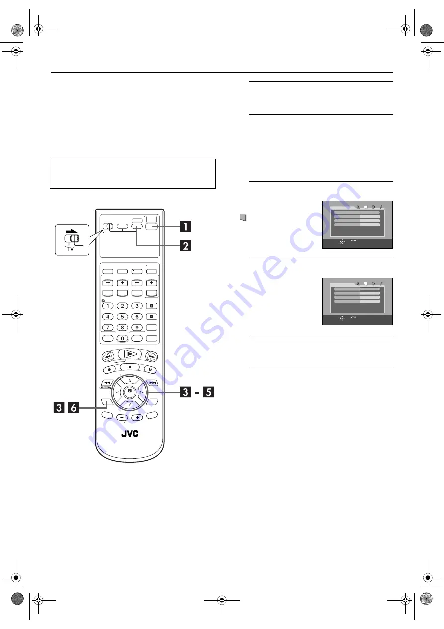
Monitor Set

(DVD deck)

You can select the monitor type depending the TV used 
when you play back DVD VIDEO discs recorded for 
wide-screen TVs.

A

Turn on the unit.

Press 

POWER

 (

1

).

B

Select the DVD deck.

On the unit

Press 

VCR/DVD

 repeatedly so that the DVD indicator 

lights up.

On the Remote

Press 

DVD

 so that the DVD indicator lights up.

C

Access the DVD Set Up menu screen.

D

Select the mode.

E

Select the mode setting.

Press 

rt

 to select the desired setting, then press 

ENTER

.

F

Return to the normal screen.

Press 

SET UP

.

Turn on the TV and select the VCR channel (or AV 
mode).

Slide the 

TV/VCR/DVD

 switch to the right.

A

Press 

SET UP

.

B

Press 

w e

 to select 

PICTURE”.

Press 

rt

 to move the 

highlight to “MONITOR 
TYPE”, then press 

ENTER

.

4:3LB

PICTURE

MONITOR TYPE

PICTURE SOURCE

SCREEN SAVER

AUTO

ON

USE             TO SELECT,  USE OK TO CONFIRM.
TO EXIT, PRESS [SET UP].

ENTER

SELECT

FILE TYPE

AUDIO

4:3LB

PICTURE

MONITOR TYPE

PICTURE SOURCE

SCREEN SAVER

AUTO

ON

USE             TO SELECT,  USE OK TO CONFIRM.
TO EXIT, PRESS [SET UP].

ENTER

SELECT

FILE TYPE

AUDIO

XVC27U_06Index.fm  Page 18  Thursday, January 8, 2004  11:22 AM

Содержание HR-XVC22UC

Страница 1: ...XVC23UC HR XVC26US HR XVC27UC HR XVC27US For disassembling and assembling of MECHANISM ASSEMBLY refer to the SERVICE MANUAL No 86700 MECHANISM ASSEMBLY TABLE OF CONTENTS 1 PRECAUTION 1 3 2 SPECIFIC SERVICE INSTRUCTIONS 1 7 3 DISASSEMBLY 1 9 4 ADJUSTMENT 1 15 5 TROUBLESHOOTING 1 21 HR XVC22UC HR XVC23UC HR XVC26US HR XVC27UC HR XVC27US D3PV0 ...

Страница 2: ...ing system DA4 Double Azimuth head helical scan system Signal to noise ratio 45 dB Horizontal resolution 230 lines Frequency range 70 Hz to 10 000 Hz Normal audio 20 Hz to 20 000 Hz Hi Fi audio Input Output RCA connectors IN 1 OUT 1 VIDEO AUDIO DVD deck Signal system NTSC Applicable disc DVD 12 cm 8 cm CD 12 cm 8 cm Audio characteristics DVD 4 Hz 22 KHz Frequency response CD 4 Hz 20 KHz S N Ratio ...

Страница 3: ... 9 When a power cord has been replaced check that 10 15 kg of force in any direction will not loosen it Fig 1 1 2 10 Also check areas surrounding repaired locations 11 Products using cathode ray tubes CRTs In regard to such products the cathode ray tubes themselves the high volt age circuits and related circuits are specified for compli ance with recognized codes pertaining to X ray emission Conse...

Страница 4: ...lug prongs and externally ex posed accessible parts Use an AC voltmeter to measure across both terminals of load Z See Fig 1 1 9 and follow ing Fig 1 1 12 Fig 1 1 9 5 Grounding Class 1 model only Confirm specified or lower grounding impedance between earth pin in AC inlet and externally exposed accessible parts Video in Video out Audio in Audio out or Fixing screw etc Measuring Method Connect mill...

Страница 5: ...rformed 1 Ground the workbench Ground the workbench by laying conductive material such as a conductive sheet or an iron plate over it before placing the traverse unit optical pickup on it 2 Ground yourself Use an anti static wrist strap to release any static electricity built up in your body 3 Handling the optical pickup In order to maintain quality during transport and before installation both si...

Страница 6: ...f these half fixed resistors for laser power adjustment 1 3 2 Destruction of Traverse Unit and Laser Pickup by Static Electricity Laser diodes are easily destroyed by static electricity charged on clothingor the human body Before repairing peripheral elements of the traverse unit or pickup be sure to take the following electrostatic protection 1 Wear an antistatic wrist wrap 2 With a conductive sh...

Страница 7: ...ted to the major parts first before performing step 2 When carrying out diagnosis and repair of the Main board assembly in the Service position be sure to ground both the Main board and Mechanism assem blies If they are improperly grounded there may be noise on the playback picture or FDP counter display may move even when the mechanism is kept in an inop erative status In order to diagnose the pl...

Страница 8: ... sulting in possible tape damage Note Absolutely avoid sweeping the upper drum vertically as this will cause damage to the video head 1 When cleaning the upper drum especially the video head soak a piece of closely woven cloth with alcohol and while holding the cloth onto the upper drum by the fingers turn the upper drum counterclockwise 2 To clean the parts of the tape transport system other than...

Страница 9: ...ront panel assembly lift the Cassette door slightly Fig 3 1a Note 3a When reattaching the Mechanism assembly secure the screws S3a to S3b in the order of 1 2 3 Note 3b When reattaching the Mechanism assembly be sure to align the phase of the Rotary encoder on the Main board assembly When reattaching the Mechanism assembly set the Mecha nism assembling mode See MECHANISM ASSEMBLY SERVICE MANUAL No ...

Страница 10: ...the motor or shaft Be careful not to touch other parts especially the vid eo heads Also take care not to damage the connectors Fig 3 1c Note 3c S3c S3c S3e S3e S3d S3d Mechanism assembly Drum assembly NOTE Attach the Drum assembly appropriately since the installation state of the Drum assembly influences the FM WAVEFORM LINEARITY greatly HOOK Shaft Video heads Motor ...

Страница 11: ...te 2b WR3a Note 2b WR3b Note 2b WR4b Note 2b Make a crease Phase alignment Accord the position of V gap on R ENCORDER and PWB silk Accord the position of Boss on R ENCORDER and PWB silk JS3001 OK NG CN CN CN 90 NOTE right side back side supporting side electrode side 1 Insert direction of FFC WIRE as follows 3 Insert the wire to even the root of connector completely at the same time as inserting e...

Страница 12: ... of the tray is removed from b of the loading base Then remove the tray upward See Figure 3 2d Attaching the tray Engage c of the loading base to the projection of the tray while tilting the tray to the left Turn the tray in a direction of the ar row and attach the slide bracket See Figure 3 2e Note Prior to the procedure above move the slide cam in a direction of the arrow so that d of the slide ...

Страница 13: ... 3 2j Prior to the following procedure remove the traverse mecha nism assembly 1 Remove the two arms of the elevator from the two parts f by moving the arms in a direction of the arrow 2 Pull out the elevator in a rear direction Attaching the elevator Engage the two holes g to the two shafts on the front part of the elevator And then attach the elevator Fig 3 2h Fig 3 2j Loading mechanism assembly...

Страница 14: ... the following procedure remove the traverse mecha nism assembly 1 Remove one screw D attaching the plate 2 Remove the plate and the leaf spring 3 Lift i of the shaft 1 and pull out the shaft 1 from j 4 Remove k of the pickup from the shaft 2 Attaching the pickup 1 Engage k of the pickup to the shaft 2 2 Insert the shaft 1 in j and attach the shaft 1 to i 3 Attach the leaf spring and then attach t...

Страница 15: ...herwise specified on the relevant adjustment chart The switches that are not list ed below can be set as desired If the VCR is not equipped with the functions detailed below setup is not required 4 1 6 Manual tracking mode Auto tracking ON OFF set ting 1 In order to set to the manual tracking mode during tape playback press the SP EP LP button on the remote con trol unit Each press of the button s...

Страница 16: ...ernal trigger signal to D FF E to observe the V PB FM waveform at the measuring point D 3 Set the VCR to the manual tracking mode 4 Make sure that there is no significant level drop of the V PB FM waveform caused by the tracking operation with its generally parallel and linear variation ensured Perform the following adjustments when required See Fig 4 2c 5 Reduce the V PB FM waveform by the tracki...

Страница 17: ...is maximized for the second time and then tighten the screws 4 and 5 temporarily 6 Play an alignment tape A2 and set to the manual tracking mode 7 Fine adjust A C head base position to maximize the FM waveform and then tighten the screws 4 and 5 firmly 8 Play alignment tapes A1 and A2 and confirm that the FM waveforms are maximized when the tracking is at the cen ter position Fig 4 2e Fig 4 2f Sig...

Страница 18: ... enters the eject mode repeat steps 1 to 5 again 7 Play back the alignment tape A2 again confirm that the switching point is the specified value G Fig 4 3a Switching point 4 3 1 2 Slow tracking preset 1 Record the signal A2 in the mode B1 and play back the recorded signal 2 Set the VCR to the manual tracking mode 3 Set the VCR to the FWD slow 1 6x mode 4 Transmit the code F from the Jig RCU to adj...

Страница 19: ...tialize and then confirm whether the symptoms are improved or not After servicing before returning the main body to a customer Initialized unit should be returned to a customer 1 Set the unit to the test mode 2 Press PAUSE key of the remote controller or transmit the code 6F from the Jig RCU 3 When initialization is completed the PLAY mark is indicated in the FDP 4 4 4 All initialization method Pl...

Страница 20: ...ion number NOTE Status of this adjustment can be judged by the number displayed at test mode as follows NOTE As for a disc used for adjustment Disc should be mounted Mounting means to display READ after the disc is inserted and then display the disc informa tion Disc need not be played If you do not have test disc either VT 501 DVD or CTS 1000 CD DA use a commercial disc for DVD dual layer soft wa...

Страница 21: ...bly off the hook and detach it from the tape 4 Remove the screw a of the side frame L R 5 Hold the slack tape and cassette cover together lift the cassette tape top frame cassette holder and side frames L R together from the rear and remove them by dis en gaging the hooks a and b Fig 5 1c 6 Take up the slack of the tape into the cassette This com pletes removal of the cassette tape 5 2 Manually re...

Страница 22: ...ethod Depress the 3 button after the data code is set Jig RCU 0 00 E 1E 1 1 2 2 3 34 4 5 5 6 6 7 7 8 8 9 9 10 Normal display EMG content display Latest See 5 3 4 EMG content display Previous See 5 3 4 EMG detail information 1 See 5 3 5 Deck operation mode EMG detail information 1 See 5 3 5 Mechanism operation mode EMG detail information 1 See 5 3 5 Mechanism sensor information and Mechanism mode p...

Страница 23: ... Cassette tape type 2 higher 8 bits See EMG detail of information 2 OO Cassette tape type 2 lower 8 bits See EMG detail of information 2 PP General data display area YY General data display area AA BB CC DD EE FF GG HH I I J J KK L L MM NN OO PP QQ RR SS TT UU VV WW XX YY Display h Encoder data See Mechanism mode sequence Cassette tab present 1 Cassette tab broken 0 Cassette absent 1 Cassette pres...

Страница 24: ...rmally but the FG pulse is not generated due to a supply reel sensor failure 3 Power SW5V is not supplied to the reel sensor on the tape winding side 1 The drum could not start or the drum rotation has stopped due to too large a load on the tape because 1 The tape tension is abnormally high 2 The tape is damaged or a foreign object grease etc adheres to the tape 2 The drum FG pulse did not reach t...

Страница 25: ...uring mechanism initialization 04 Ejecting cassette ULSTOP to EJECT 05 Inserting cassette EJECT to ULSTOP 06 Loading tape ULSTOP to PLAY 07 Unloading tape PLAY to ULSTOP 08 Transition from pinch roller ON to STOP 09 Transition from pinch roller OFF to STOP PLAY to OFFSTOP 0A Transition from pinch roller OFF to STOP at power OFF 0B Transition from pinch roller ON to STOP at power ON 0C Transition t...

Страница 26: ...tion 7 ULSTOP ULSTOP position 8 ULSTOP UPPER Intermodal position 9 UPPER Loading unloading tape A UPPER ONSTOP Intermodal position B ONSTOP PLAY position C PLAY FWD SS Intermodal position D FWD SS FWD FWD Still Slow position E FWD SS REV Intermodal position F REV REV REV Still Slow position 0 REV OFFSTOP Intermodal position 1 OFFSTOP Pinch roller OFF position 2 OFFSTOP FFREWB Intermodal position 3...

Страница 27: ...s the motor drive voltage gone out to IC201 11 or 14 3 TRSDRV Is the signal input IC301 75 4 TRVSW is the signal input from microcomputer IC301 79 5 4 4 Focus ON NG Is FODRV signal sent R254 Pattern IC301 148 Is driving voltage sent IC201 9 10 If NG pattern driver mechanical unit Mechanical unit is defective 5 4 5 Tracking ON NG Mechanical unit is defective Because the self adjustment cannot be no...

Страница 28: ...age stops The image is blocked when going to outer though it is normal in suroundings in the disk and the stopping sympton increases There is a possibility with bad jitter value for such a symptom 5 4 12 CD During normal playback operation 1 Is TOC reading normal Displays total time for CD DA Shifts to double speed mode for V CD 2 Is playback afterwards possible 3 When can not do a normal playback...

Страница 29: ...8 WPC Printed in Japan JVC SERVICE ENGINEERING COMPANY OF AMERICA DIVISION OF JVC AMERICAS CORP www jvcservice com US Only JVC CANADA INC Head office 21 Finchdene Square Scarborough Ontario M1X 1A7 416 293 1311 ...

Страница 30: ... that do not meet specifications may cause trouble in regard to safety and performance We recommend that genuine JVC parts be used 1 EXPLODED VIEW 1 1 PACKING AND ACCESSORY ASSEMBLY M1 The instruction manual to be provided with this product will differ according to the destination 302 301 FINAL ASSY M2 SPEC OF BARCODE 311 303 302 316 317 310 307 312 313 308 306 306A ...

Страница 31: ...c j f j LP FRAME NO LABEL DVD BRACKET BOARD ASSY 90 a a MECHANISM ASSY M4 DVD UNIT M5 M6 98 99 MAIN BOARD ASSY 03 502 503 503 505 515 515 515 519 518 504 504 504 504 504 504 518 518 520 565 509 563 565 565 564 508 561 560 514 521 521 511 561 561 562 562 516 510 517 570 517 517 510 566 j j 501B 501A 501 507 j j ...

Страница 32: ...G FROM DIRECTION FIG 4 FIG 5 CN7103 CN7191 back side DRAWING FROM DIRECTION A C HEAD CN2001 TOP SIDE BOTTOM SIDE JACK BOARD ASSY 36 FITTING DISPLAY BOARD ASSY 28 CN7191 CN7003 CN3102 CN7302 CN7301 CN8301 CN503 CN501 back side right side Make a crease CN3102 Make a crease CN1 FOR AVOID FFC WIRE DISTURB CASSETTE IN AND OUT NOTE FFC WIRE SHOULD BE POSITIONED BELLOW CASSETTE DOOR WR4 WR3 WR1 WR2 WR5 5...

Страница 33: ... 75 74 38 105 105 107 107 112 123 151 113 115 124 125 79 82 21 4 117 44 26 3 58 52 57 56 58 55 90 37 77 72 116 50 112 122 110 126 126 89 36 73 69 102 70 134 78 76 71 120 42 85 46 47 81 83 80 49 119 53 111 114 118 121 96 93 94 95 64 65 18A 19 22 20 16 23A 63 66 59 62 68 24 18 61 60 67 23 23B 18B WR2 A C HEAD BOARD ASSY 12 LOADING MOTOR BOARD ASSY 55 AA AA AA AA AA AA AA AA AA AA AA AA AA BB BB BB B...

Страница 34: ...FD 4007ZY2 JVG 31N Grease ETU DE2 31C CN101 CN101 BEND WIRE AT THE PWB EDGE AFTER INSERTING WIRE LETTER SIDE 63 3mm 0 1mm CN201 A A BACK SIDE DVD SERVO CONTROL BOARD ASSY 99 1 2 3 3 6 5 4 7 10 22 21 20 11 11 12 13 14 15 16 17 19 9 8 26 23 24 25 27 28 28 29 29 18 ...

Страница 35: ... ASSEMBLY M6 SWITCH BOARD ASSY 98 EMU DE2 31YC BACK SIDE MOLD HOOK PWB TO CHASSIS HOOK WIRES 2 WIRE ARRANGEMENT AND SOLDERING 0 BACK SIDE 13 13 DVD SERVO CONTROL BOARD ASSY 99 DVD TRAVERSE MECHANISM M5 1 2 3 6 4 5 7 8 9 11 11 12 12 14 13 13 ...

Страница 36: ...A STICKER TOP C E 570 LP30002 0B7A SPACER WR1 QUQ112 2212CG FFC WIRE DISPLAYCN7003 MAINCN3102 WR2 QUQ112 1010CG FFC WIRE JACKCN7191 MAINCN3103 WR3 QUQ210 1916CC FFC WIRE DVDUNITCN501 MAINCN7301 WR4 QUQ210 1716CC FFC WIRE DVDUNITCN503 MAINCN7302 WR5 QUQ210 0510CC FFC WIRE DVDUNITCN1 MAINCN8301 Symbol No Part No Part Name Description Local 1 LP21039 001X MAIN DECK ASSY A D 1 LP21039 001Y MAIN DECK A...

Страница 37: ... 1 LE10283 012A LOADER SUB ASSY 2 QAR0197 001 MOTOR MABUCHI 3 LV42087 002A MOTOR PULLEY 4 QYSPSPU1730Z SCREW FOR MOTOR x2 5 LE40897 001A BELT 6 LE31046 003A CLAMPER 7 LV42930 003A P C MAGNET 8 LE40899 001A YOKE 9 LE40906 001A SPECIAL SCREW 11 LE40900 003A INSULATOR x2 12 LE40900 005A INSULATOR x2 13 LE40901 001A SPECIAL SCREW x4 14 QYWFM419025 WASHER 1 9mm 21 4mmx0 02mm Symbol No Part No Part Name...

Страница 38: ...DIODE D5208 1S4 T2 SB DIODE D5208 or AW04 T2 SB DIODE D5208 or SBO40 T2 SB DIODE D5209 PG104RS T2 FR DIODE D5209 or 10ERB20 T2 FR DIODE D5209 or 1F4G T2 FR DIODE D5209 or AU01Z T2 FR DIODE D5209 or 1SR153 400 T2 FR DIODE D5212 SB240 F26 SB DIODE D5212 or RK14LF B2 SBD D5212 or 21DQ04 F SBD D5213 1F4G T2 FR DIODE D5213 or 10ERB20 T2 FR DIODE D5301 MTZJ15C T2 Z DIODE D5301 or RD15ES B3 T2 Z DIODE D5...

Страница 39: ...W J Symbol No Part No Part Name Description Local C4010 NCB31EK 223X C CAPACITOR 0 022uF 25V K C4011 NCB31CK 104X C CAPACITOR 0 1uF 16V K C4012 QEKJ1HM 224Z E CAPACITOR 0 22uF 50V M C4014 NDC31HJ 101X C CAPACITOR 100pF 50V J C4015 NCB31HK 221X C CAPACITOR 220pF 50V K C5001 QFZ9077 473 MPP CAPACITOR 0 047uF 275V M C5003 QCZ9079 101 C CAPACITOR 100pF AC250V K C5004 QCZ9079 472 C CAPACITOR 4700pFAC25...

Страница 40: ...bol No Part No Part Name Description Local R3054 NRSA63J 102X MG RESISTOR 1kΩ 1 16W J R3058 NRSA63J 472X MG RESISTOR 4 7kΩ 1 16W J R3061 QRE141J 331Y C RESISTOR 330Ω 1 4W J R3062 QRE141J 331Y C RESISTOR 330Ω 1 4W J R3063 NRSA63J 102X MG RESISTOR 1kΩ 1 16W J R3064 NRSA63J 102X MG RESISTOR 1kΩ 1 16W J R3065 NRSA63J 271X MG RESISTOR 270Ω 1 16W J R3069 QRE141J 102Y C RESISTOR 1kΩ 1 4W J R3074 NRSA63J ...

Страница 41: ... 1 16W J R8251 NRSA63J 222X MG RESISTOR 2 2kΩ 1 16W J R8252 NRSA63J 222X MG RESISTOR 2 2kΩ 1 16W J R8259 NRSA63J 0R0X MG RESISTOR 0Ω 1 16W J R8260 NRSA63J 0R0X MG RESISTOR 0Ω 1 16W J R8262 NRSA63J 222X MG RESISTOR 2 2kΩ 1 16W J R8263 NRSA63J 222X MG RESISTOR 2 2kΩ 1 16W J R8301 QRE141J 4R7Y C RESISTOR 4 7Ω 1 4W J Symbol No Part No Part Name Description Local L5 QQL29BJ 100Z P COIL 0 40Ω 10uH J L7 ...

Страница 42: ...8A QRS X TRANSISTOR Q7011 2SC2412K QRS X TRANSISTOR Symbol No Part No Part Name Description Local Q7011 or 2SD601A QRS X TRANSISTOR Q7011 or 2SC3928A QRS X TRANSISTOR Q7012 2SC2412K QRS X TRANSISTOR Q7012 or 2SD601A QRS X TRANSISTOR Q7012 or 2SC3928A QRS X TRANSISTOR Q7013 2SC2412K QRS X TRANSISTOR Q7013 or 2SD601A QRS X TRANSISTOR Q7013 or 2SC3928A QRS X TRANSISTOR Q7014 2SC2412K QRS X TRANSISTOR...

Страница 43: ...104X C CAPACITOR 0 1uF 16V K C313 NCB31CK 104X C CAPACITOR 0 1uF 16V K C314 NCB31CK 104X C CAPACITOR 0 1uF 16V K C315 NCB31CK 104X C CAPACITOR 0 1uF 16V K C316 NCB31CK 104X C CAPACITOR 0 1uF 16V K C317 NCB31CK 104X C CAPACITOR 0 1uF 16V K C318 NCB31CK 104X C CAPACITOR 0 1uF 16V K C319 NCB31CK 104X C CAPACITOR 0 1uF 16V K C320 NCB31CK 104X C CAPACITOR 0 1uF 16V K C321 NCB31CK 104X C CAPACITOR 0 1uF...

Страница 44: ... 1 16W J R339 NRSA63J 0R0X MG RESISTOR 0Ω 1 16W J R340 NRSA63D 303X MG RESISTOR 30kΩ 1 16W D R341 NRSA63D 362X MG RESISTOR 3 6kΩ 1 16W D R342 NRSA63D 222X MG RESISTOR 2 2kΩ 1 16W D R343 NRSA63J 0R0X MG RESISTOR 0Ω 1 16W J R344 NRSA63J 6R8X MG RESISTOR 6 8Ω 1 16W J R345 NQR0129 002X FERRITE BEADS R351 NRSA63J 681X MG RESISTOR 680Ω 1 16W J R352 NRSA63J 105X MG RESISTOR 1MΩ 1 16W J R357 NRSA63J 101X ...

Страница 45: ...RDER INSTRUCTIONS LPT0892 001A HR XVC26U For Customer Use Enter below the Model No and Serial No which are located on the rear of cabinet Retain this information for future reference Model No Serial No XVC26U_02Cov1 fm Page 1 Thursday January 8 2004 2 54 PM ...

Страница 46: ...ed by JVC could void user s authority to operate the equipment CAUTION THIS PRODUCT USES A LASER SYSTEM USE OF CONTROLS OR ADJUSTMENTS OR PERFORMANCE OF PROCEDURES OTHER THAN THOSE SPECIFIED HEREIN MAY RESULT IN HAZARDOUS RADIATION EXPOSURE DO NOT OPEN COVERS AND DO NOT REPAIR YOURSELF REFER SERVICING TO QUALIFIED PERSONNEL Declaration of Conformity Model Number HR XVC26U Trade Name JVC Responsibl...

Страница 47: ... fire or electric shock 4 Power Cord Protection Power supply cords should be routed so that they are not likely to be walked on or pinched by items placed upon or against them paying particular attention to cords at plugs convenience receptacles and the point where they exit from the product 5 Ventilation Slots and openings in the cabinet are provided for ventilation To ensure reliable operation o...

Страница 48: ...ervicing to qualified service personnel 2 Damage Requiring Service Unplug this product from the wall outlet and refer servicing to qualified service personnel under the following conditions a When the power supply cord or plug is damaged b If liquid has been spilled or objects have fallen into the product c If the product has been exposed to rain or water d If the product does not operate normally...

Страница 49: ...ssette 1 DO NOT place the unit in an environment prone to extreme temperatures or humidity in direct sunlight in a dusty environment in an environment where strong magnetic fields are generated on a surface that is unstable or subject to vibration 2 DO NOT block the unit s ventilation openings or holes If the ventilation openings or holes are blocked by a newspaper or cloth etc the heat may not be...

Страница 50: ...42 Basic Playback 42 Playback Features 43 Using the on screen bar 48 Parental Lock 58 About MP3 Disc 62 MP3 Playback 63 About JPEG Disc 65 JPEG Playback 66 EDITING VCR DECK 68 Edit From A Camcorder 68 Edit To Or From Another Video Recorder 69 Dubbing from DVD to VCR 70 EDITING DVD DECK 71 Digital Audio Dubbing 71 REMOTE 72 Remote Control Functions 72 Connecting To A Dolby Digital Decoder or An Amp...

Страница 51: ...image and sound may be momentarily distorted This is not a malfunction Unplayable Discs The following types of discs cannot be played using this unit Do not attempt to play back any kind of disc that is damaged cracked warped or repaired with adhesive tape or discs in unusual shapes heart shaped octagonal or other forms If such discs are accidentally played back it may cause noise that can lead to...

Страница 52: ...cene has a scene number For more details refer to Locating a desired scene using the menu of the Video CD with PBC 墌 pg 43 Mark Description Number of subtitles Number of angles Recorded under the standard 4 3 aspect ratio Screen includes black bands at top and bottom of image which has a standard 4 3 aspect ratio letter box Video playback is in Wide video mode 16 9 on wide televisions but in lette...

Страница 53: ...ince discs are made of plastic they are easily damaged If a disc gets dirty dusty scratched or warped the images and sound will not be picked up correctly and such a disc may cause the unit to malfunction Label side Do not damage the label side stick paper to or use any adhesive on its surface Storage Make sure that discs are kept in their cases If discs are piled on top of one another without the...

Страница 54: ...ndicator 墌 pg 42 H Play Button PLAY 4 墌 pg 28 42 I DVD Open Close Button OPEN CLOSE x 墌 pg 42 J VHS Eject Button EJECT x 墌 pg 28 33 K Video Audio Input Connectors VIDEO AUDIO 墌 pg 68 L Remote Sensor M Front Display Panel 墌 pg 11 N Record Button REC 7 墌 pg 33 O Rewind Button REW 3 墌 pg 28 29 44 P Fast Forward Button FF 5 墌 pg 28 29 44 Q Channel Button CH 墌 pg 33 R Progressive Scan Button PROGRESSIV...

Страница 55: ...T 墌 pg 16 H Audio Output Connectors AUDIO OUTPUT L R I Antenna Output Connector VHF UHF OUT 墌 pg 14 These connectors are only for DVD deck FRONT DISPLAY PANEL A Operation Mode Indicators B Channel Clock Auxiliary Input Mode Display F 1 VCR deck only Counter Display VCR deck Tape Speed SP EP VCR deck only Multi information window DVD deck The current group title track chapter number s time and stat...

Страница 56: ...ows you where you are on the tape NOTE Depending on the type of tape being used the tape position indicator may not appear correctly D Index number 墌 pg 30 E Tape Remaining Time Indicator 墌 pg 35 F Counter Display G Audio Mode Display 墌 pg 32 H SAP Indicator 墌 pg 35 I Stereo Program Indicator 墌 pg 35 J Day Clock Display K Channel Position Number Auxiliary Input Indicator F 1 L Cassette Loaded Mark...

Страница 57: ... TITLE 墌 pg 54 Angle Button ANGLE 墌 pg 55 X Channel Button CH 墌 pg 33 Y Programing Button PROG 墌 pg 36 Z Timer Button TIMER 墌 pg 37 a Weekly Button WEEKLY 墌 pg 37 b Program Check Button PROG CHECK 墌 pg 38 Return Button RETURN 墌 pg 43 c Satellite Auto Recording Button REC LINK 墌 pg 41 d 10 Button e Auxiliary Button AUX 墌 pg 68 f Fast Forward Button FF 5 墌 pg 28 29 44 g Pause Button PAUSE 9 墌 pg 29 ...

Страница 58: ...e clock and tuner channels will automatically be set when the antenna is connected and when the AC power cord is first connected to an AC outlet If AUTO and the channel indicator are displayed on the front display panel before the unit is powered on the clock and tuner channels are being set automatically Wait for the time to be displayed on the front display panel before turning on the unit E Set...

Страница 59: ...ess CH on the Remote to select CH off then press ENTER NOTES You can obtain high quality S VIDEO pictures If your TV is not stereo capable use the unit s AUDIO OUTPUT connectors to connect to an audio amplifier for Hi Fi stereo sound reproduction To operate the unit with your TV using the S VIDEO connection set your TV to its AV mode You can also use the TV VCR button on the unit s Remote to set y...

Страница 60: ...en press ENTER NOTES You can obtain high quality component video pictures If your TV is not stereo capable use the unit s AUDIO OUTPUT connectors to connect to an audio amplifier for Hi Fi stereo sound reproduction To operate the unit with your TV using the Component Video connection set your TV to its AV mode You can also use the TV VCR button on the unit s Remote to set your TV to the AV mode Fo...

Страница 61: ...k setting data from the PBS channel If this function is taking a considerable amount of time it may be necessary to perform the Semiauto or Manual Clock Set procedure INFORMATION If AUTO CLOCK is set to ON 墌 pg 25 the clock will be adjusted automatically by the host channel every hour except 11 00 PM midnight 1 00 AM and 2 00 AM using the incoming PBS channel clock setting data This automatic cloc...

Страница 62: ...ode E Select the mode setting Press rt to select the desired setting then press ENTER F Return to the normal screen Press SET UP Turn on the TV and select the VCR channel or AV mode Slide the TV VCR DVD switch to the right A Press SET UP B Press w e to select PICTURE Press rt to move the highlight to MONITOR TYPE then press ENTER 4 3LB PICTURE MONITOR TYPE PICTURE SOURCE SCREEN SAVER AUTO ON USE T...

Страница 63: ... and the bottom of the screen 4 3 PS Pan Scan Select this when the aspect ratio of your TV is 4 3 conventional TV While viewing a wide screen picture the black bars do not appear however the left and right edges of the pictures will not be shown on the screen Pan Scan Letter Box In general DVD VIDEO disc are produced for a wide screen TV with 16 9 aspect ratio Material with this ratio will not fit...

Страница 64: ... up On the Remote Press VCR so that the VCR indicator lights up C Access the Main Menu screen Press SET UP D Access the Initial Set screen E Select the language F Return to the normal screen Press SET UP Turn on the TV and select the VCR channel or AV mode Slide the TV VCR DVD switch to the right Press rt to move the highlight bar arrow to INITIAL SET then press ENTER or e Press rt to move the hig...

Страница 65: ...ss the DVD Set Up menu screen D Select the mode E Select the mode setting Press rt to select the desired setting then press ENTER F Return to the normal screen Press SET UP A Press SET UP B Press w e to select LANGUAGE Press rt to move the hightlight to ON SCREEN LANGUAGE then press ENTER ENGLISH ENGLISH ENGLISH OFF LANGUAGE MENU LANGUAGE ON SCREEN LANGUAGE AUDIO LANGUAGE SUBTITLE USE TO SELECT US...

Страница 66: ... Set Up menu screen D Select the mode E Select the mode setting Press rt to select the desired setting then press ENTER See Language Code List 墌 pg 23 F Return to the normal screen Press SET UP NOTE When the selected language is not available on the disc the disc s default menu language is played back A Press SET UP B Press w e to select LANGUAGE Press rt to move the hightlight to MENU LANGUAGE th...

Страница 67: ...PS PT QU RM Inupiak Indonesian Icelandic Hebrew Yiddish Javanese Georgian Kazakh Greenlandic Cambodian Kannada Korean KOR Kashmiri Kurdish Kirghiz Latin Lingala Laothian Lithuanian Latvian Lettish Malagasy Maori Macedonian Malayalam Mongolian Moldavian Marathi Malay MAY Maltese Burmese Nauru Nepali Dutch Norwegian Occitan Afan Oromo Oriya Panjabi Polish Pashto Pushto Portuguese Quechua Rhaeto Roma...

Страница 68: ...ly so that the VCR indicator lights up On the Remote Press VCR so that the VCR indicator lights up C Access the Main Menu screen Press SET UP D Access the Initial Set screen E Access the Clock Set screen Turn on the TV and select the VCR channel or AV mode Slide the TV VCR DVD switch to the right Press rt to move the highlight bar arrow to INITIAL SET then press ENTER or e Press rt to move the hig...

Страница 69: ...k setting data of a PBS channel from an adjacent time zone or from an incorrect PBS channel from a cable TV system If you selected AUTO for the host channel in step B be sure to select the correct time zone manually E Complete the Semiauto Clock Set Press SET UP to return to normal screen Manual Clock Set First follow steps A to E in Preparations 墌 pg 24 then go to the following steps A Set time d...

Страница 70: ...HANNEL SET then press ENTER or e You can automatically set the receivable channels in your area in the order of their frequencies When Auto Channel Set is complete SCAN COMPLETED appears on the TV screen If the scan was unsuccessful SCAN COMPLETED NO SIGNAL appears on screen Check the connections and start again F Return to the normal screen Press SET UP Turn on the TV and select the VCR channel o...

Страница 71: ... Press rt to move the highlight bar arrow to TUNER SET then press ENTER or e E Access the Manual Channel Set screen F Add or skip the desired channels To add channels A Press the number keys to input a channel number you want to add B Press ENTER or e to set to ADD C Repeat A to B to add other channels To skip channels A Press rt or the number keys to select a channel number you want to skip B Pre...

Страница 72: ...lide the TV VCR DVD switch to the right Clean the video heads using a dry cleaning cassette ECL 3F when Rough poor picture appears while a tape is played back The picture is unclear or no picture appears USE CLEANING CASSETTE appears on the screen only with SUPERIMPOSE set to ON 墌 pg 75 NOTE The heads get dirty in the following cases in an environment prone to extreme temperature or humidity in a ...

Страница 73: ...Variable Speed Search During playback press FF 5 for forward variable speed search or REW 3 for reverse variable speed search The speed changes for each direction by pressing REW 3 and FF 5 repeatedly When pressing FF 5 SP 5x 7x EP 11x 21x When pressing REW 3 Once REW 3 is pressed reverse search starts in 1x normal playback speed After this process each press of REW 3 changes the search speed betw...

Страница 74: ... B from the current position press INDEX 2 twice To locate the beginning of D from the current position press INDEX 6 once When the specified index code is located playback begins automatically Instant ReView Simply by pressing a single button the unit power comes on rewinds and begins playback of the last timer recorded program If you have several programs recorded you can easily access any of th...

Страница 75: ...3 then press TIMER within 2 seconds d For Automatic Cassette Ejection After Tape Rewind Press REW 3 then press EJECT x within 2 seconds Repeat Playback Your unit can automatically play back the whole tape 100 times repeatedly 1 Start playback Press PLAY 4 2 Activate Repeat Playback Press PLAY 4 and hold for over 5 seconds then release The Play indicator on the front display panel blinks slowly Aft...

Страница 76: ...HI FI R and NORM and will play back the one you select During Playback Pressing A MONITOR changes the soundtrack as follows You can also select the soundtrack on the Function Set screen 墌 pg 76 NOTES HIFI should normally be selected In this mode Hi Fi stereo tapes are played back in stereo and the normal audio track is played back automatically for tapes with only normal audio SUPERIMPOSE must be ...

Страница 77: ...n Press SP EP again to change the setting while the tape speed is displayed on the TV screen E Start recording Press and hold REC 7 and press PLAY 4 on the Remote or press REC 7 on the unit F Pause Resume recording Press PAUSE 9 Press PLAY 4 to resume recording You can select channel during the Record Pause mode G Stop recording Press STOP 8 Then press EJECT x on the VCR deck to remove the cassett...

Страница 78: ... 0 30 appears on the front display panel 3 Set the recording duration If you want to record for more than 30 minutes press REC 7 to extend the time Each press extends recording time by 30 minutes NOTES You can only perform ITR using the REC 7 button on the unit s front panel Still picture playback stops automatically after 5 minutes to protect the heads When the end of the tape is reached during t...

Страница 79: ...ayed during playback NOTES When you press ON SCREEN the on screen display appears on the TV screen for 5 seconds then the displays other than the counter disappears To clear the counter display press ON SCREEN Depending on the type of tape being used the tape remaining time reading may not appear right away or is not correct may sometimes appear with blinking or the display may blink on occasion S...

Страница 80: ...0 minute increments or press and release repeatedly to move 1 minute at a time E Enter the program date Press DATE The current date appears on the TV screen The date you enter appears in its place Before performing Express Timer Programing Make sure that the unit s built in clock is set properly Insert a cassette with the safety tab in place The unit will come on automatically Turn on the TV and s...

Страница 81: ...ress WEEKLY number key 9 for weekly serials or DAILY number key 8 for daily serials Monday Friday Either WEEKLY or DAILY appears on the TV screen Pressing the button again makes the corresponding indication disappear NOTES You can program this unit to timer record as many as 8 programs If you try to program the unit to record a ninth PROGRAM FULL appears on the TV screen To record the extra progra...

Страница 82: ...hange programs A Disengage the timer mode Press TIMER then press POWER 1 B Access the Program Check screen C Access the Program screen Press PROG CHECK Press PROG CHECK again to check more information Each time you press PROG CHECK the next program s information appears XVC27U_01 book Page 38 Wednesday January 7 2004 10 48 AM ...

Страница 83: ...ncel a program To change program settings press the appropriate button START STOP DATE CH DAILY number key 8 WEEKLY number key 9 and or SP EP E Return to the normal screen Press PROG CHECK as many times as necessary If there are still some programs remaining go on to step F F Return to the timer mode Press TIMER XVC27U_01 book Page 39 Wednesday January 7 2004 10 48 AM ...

Страница 84: ...ED appears on the TV screen for about 5 seconds then the normal screen appears To change a program press the appropriate button START STOP DATE CH DAILY number key 8 WEEKLY number key 9 and or SP EP when the Program screen on which you want to make changes is shown then press ENTER PROGRAM COMPLETED appears on the TV screen for about 5 seconds then the normal screen appears NOTE If the overlap is ...

Страница 85: ...o Recording is in progress For timer programing of the DBS receiver refer to the instruction manual of the DBS receiver Satellite Auto Recording is not possible if your DBS receiver does not have a timer Pressing the unit s POWER 1 button while Satellite Auto Recording is in progress turns off the unit s power and disengages the Satellite Auto Recording mode If there are more than one satellite pr...

Страница 86: ...DVD deck REGION CODE ERROR appears on the TV screen For details refer to Region Number 墌 pg 7 With Video CD discs with PBC control or some DVD discs the menu display may appear on the TV screen after starting playback In this case select an item which you want to play back from the menu Otherwise the playback cannot go forward Refer to Locating a desired scene using the menu of the Video CD with P...

Страница 87: ...DVD menu DVD VIDEO discs may have two types of the menus top menu and disc menu Top menu DVD discs generally have their own menus which show the disc contents These menus contain various items such as titles of a movie names of songs or artist information You can locate a desired scene by using the top menu displayed on the TV screen Press TOP MENU to access the top menu Disc menu DVD discs have t...

Страница 88: ...pending on the discs Variable Speed Search During playback press FF 5 for forward variable speed search or REW 3 for reverse variable speed search The more times you press the faster the playback picture moves To resume normal playback press PLAY 4 OR During playback press and hold SKIP 6 for forward search or press and hold SKIP 2 for reverse search While you press and hold the button the image i...

Страница 89: ...playback as the resume point To clear the resume point Press STOP 8 in stop mode Press POWER 1 to turn off the unit Eject the disc Set RESUME to OFF 墌 pg 80 2 Resume playback Press PLAY 4 The unit start playback from the resume point NOTES Resume Function does not work on the Audio CD It also may not work depending on the discs If you stop the playback of a disc for which an resume point has alrea...

Страница 90: ... back a DVD VIDEO disc recorded in the multi channel Digital format With other sources you cannot get any effect if you activate 3D Phonic function When playing back a DVD VIDEO disc recorded with the Dolby Digital that does not contain the rear signal you cannot get a correct 3D Phonic sound even if you activate 3D Phonic function The 3D Phonic function does not affect the Digital bitstream signa...

Страница 91: ...rs automatically if you do not change the selection for 10 seconds 5 Adjust the parameter Press rt repeatedly to change the setting then press ENTER The current VFP settings appear again 6 Adjust the other parameters Repeat steps 4 and 5 to adjust other parameters To return to the normal screen Press DVD PICTURE To activate your setting Press DVD PICTURE then press w e repeatedly to select USER 1 ...

Страница 92: ...s per second C Current title for DVD D Current chapter number for DVD or track number for other type of discs E Time information 墌 pg 49 F Playback status appears during playback appears during fast forward reverse appears during playback in forward slow motion reverse slow motion appears when paused appears when stopped G Select this to change time information See 5 in the illustration above 墌 pg...

Страница 93: ...See the corresponding pages for details on each function Change the time information You can change the time information in the on screen bar on the TV screen and the front display panel of the unit During playback or while stopped A Access the on screen bar Press ON SCREEN twice The on screen bar appears on the TV screen B Select menu item Press w e to move the hightlight to then press ENTER Each...

Страница 94: ...A select OFF in step C then press ENTER When using the REPEAT button A Access the repeat mode Press REPEAT during playback of the item you want to repeat Repeat mode is displayed on the TV B Select the repeat mode Press REPEAT repeatedly to select the desired repeat mode To stop Repeat Playback press STOP 8 To cancel Repeat Playback press REPEAT repeatedly until OFF appears on the TV screen The po...

Страница 95: ...d point Press ENTER at the end of the part you want to repeat point B A B Repeat Playback starts The selected part of the disc between point A and B is played repeatedly To cancel A B Repeat Playback Repeat from step A select OFF in step C then press ENTER You can also cancel Repeat Playback by pressing SKIP 2 or SKIP 6 To clear the on screen bar Press ON SCREEN NOTES A B Repeat Playback may not w...

Страница 96: ...ds elapsed If you have specified a wrong selection Press w repeatedly until the wrong number is erased then press number keys to enter the correct numbers The unit starts playback from the specified time To clear the on screen bar Press ON SCREEN NOTES When X is displayed on the TV screen in step C you have selected a point that excesses the recording time of the disc Some DVD VIDEO discs do not c...

Страница 97: ...s ENTER The unit starts playback from the selected chapter If you have specified a wrong selection Enter the appropriate number keys again To clear the on screen bar Press ON SCREEN NOTES When X is displayed on the TV screen in step C the chapter you have selected is not contained in the disc or chapter search does not work on the disc Chapter Search starts automatically when you select the desire...

Страница 98: ...en press SUB TITLE until OFF is selected For DVD VIDEO Some subtitle languages are abbreviated in the pop up window See Language Code List 墌 pg 23 For SVCD SVCD can contain up to four subtitles Pressing SUB TITLE changes the subtitles regardless of whether the subtitles are recorded or not Subtitles will not change if no subtitle is recorded When X appears on the TV screen in step C subtitle langu...

Страница 99: ...mple The first view angle is selected out of 3 view angles recorded C Select the view angle Press rt repeatedly to select the desired view angle then press ENTER Each time you press the button the angle of the scene changes To clear the on screen bar Press ON SCREEN NOTE When X appears on the TV screen in step C the current scene is not recorded from multiple angles When using the ANGLE button A A...

Страница 100: ...press ENTER Each time you press the button the audio language changes To clear the on screen bar Press ON SCREEN NOTES Some audio languages are abbreviated in the pop up window See Language Code List 墌 pg 23 If X appears on the TV the current scene does not contain plural audio languages When using the A MONITOR button A Access the menu Press A MONITOR The following pop up window appears on the TV...

Страница 101: ...dio channel changes To clear the on screen bar Press ON SCREEN When using the A MONITOR button A Access the menu Press A MONITOR The following pop up window appears on the TV screen Example ST stereo is selected out of 3 audio channels recorded B Select the audio channel Press rt or A MONITOR repeatedly to select the desired audio channel Each time you press the button the audio channel changes Th...

Страница 102: ...hen press ENTER The PARENTAL LOCK sub menu appears on the TV screen It is possible to access the PARENTAL LOCK menu only in the stop mode when a DVD disc is loaded on the unit Press ENTER then press rt repeatedly to move the hightlight to COUNTRY CODE then press ENTER Press rt repeatedly to move the hightlight to select the country code then press ENTER See Country Area Code List for Parental Lock...

Страница 103: ... temporarily release the Parental Lock When you set the parental level strictly some discs may not be played back at all When you insert such a disc and try to play back it the following Parental Lock screen appears on the TV screen asking you whether you want the Parental Lock to be temporarily released or not A Access the password screen B Enter the password Press the appropriate number keys to ...

Страница 104: ...prus Czech Republic Germany Djibouti Denmark Dominica Dominican Republic Algeria Ecuador Estonia Egypt Western Sahara Eritrea ES ET FI FJ FK FM FO FR FX GA GB GD GE GF GH GI GL GM GN GP GQ GR GS GT GU GW GY HK HM HN HR HT HU ID IE IL IN IO IQ IR IS IT JM JO JP KE KG KH KI KM KN KP KR KW KY KZ LA LB Spain Ethiopia Finland Fiji Falkland Islands Malvinas Micronesia Federated States of Faroe Islands F...

Страница 105: ...raguay Qatar Réunion Romania Russian Federation Rwanda SA SB SC SD SE SG SH SI SJ SK SL SM SN SO SR ST SV SY SZ TC TD TF TG TH TJ TK TM TN TO TP TR TT TV TW TZ UA UG UM US UY UZ VA VC VE VG VI VN VU WF WS YE YT YU ZA ZM ZR ZW Saudi Arabia Solomon Islands Seychelles Sudan Sweden Singapore Saint Helena Slovenia Svalbard and Jan Mayen Slovakia Sierra Leone San Marino Senegal Somalia Suriname Sao Tome...

Страница 106: ...es not support packet writing discs If there are any Tracks files which are stored on a disc directly and do not belong to any Group directory the unit recognized them as belonging to an independent Group The unit plays back Groups Tracks on an MP3 disc in the alphabetical order For example if there are three title Groups one two and three on a disc the playback order is one three then two Tracks ...

Страница 107: ... disc A Press OPEN CLOSE x on the DVD deck to open the disc tray B Place the MP3 disc in the disc tray For details refer to Placing a Disc 墌 pg 9 C Press OPEN CLOSE x on the DVD deck to close the disc tray The MP3 control display appears on the TV screen when an MP3 disc is loaded 墌 pg 62 E Select the group Press rt to select the desired group then press e F Start playback Press w e to select the ...

Страница 108: ... fifteen times then press 0 once Repeat Playback You can repeat playback of the current group track or all groups While MP3 control display is on the TV A Select the mode Press REPEAT to select the desired repeat mode Each time you press REPEAT the mode changes as follows TRACK GROUP ALL OFF No indication Back to the beginning To stop Repeat Playback press STOP 8 To cancel Repeat Playback press RE...

Страница 109: ...ed now Some files on a JPEG disc may be played back distortedly Because of the disc characteristics or recording condition some discs may not be played back or it takes time to start playback The unit does not support packet writing discs If there are any Files which are stored on a disc directly and do not belong to any Group directory the unit recognized them as belonging to an independent Group...

Страница 110: ...tails refer to Placing a Disc 墌 pg 9 C Press OPEN CLOSE x on the DVD deck to close the disc tray The JPEG control display appears on the TV screen when a JPEG disc is loaded 墌 pg 65 E Select the group Press rt to select the desired group then press e F Start playback Press w e to select the desired file then press ENTER or PLAY 4 You can skip a file across a group Press SKIP 6 to skip to the first...

Страница 111: ...or all groups While JPEG control display is on the TV A Select the mode Press REPEAT to select the desired repeat mode Each time you press REPEAT the mode changes as follows GROUP ALL OFF No indication Back to the beginning B Start playback Press PLAY 4 To stop Repeat Playback press STOP 8 To cancel Repeat Playback press REPEAT repeatedly until the repeat mode display disappears on the TV screen Y...

Страница 112: ... Set the unit s input mode Press AUX number key 0 and or CH to select F 1 D Set the edit mode See PICTURE CONTROL on page 75 E Engage the Record Pause mode Use PLAY 4 REW 3 or FF 5 to locate the point where you start recording then press and hold PAUSE 9 and press REC 7 to engage the Record Pause mode F Start the camcorder Engage the Play mode of the camcorder G Start the unit Press PLAY 4 to enga...

Страница 113: ...using another recorder as the recording deck refer to its instruction manual D Set the edit mode See PICTURE CONTROL on page 75 E Engage the Record Pause mode of the recording deck Locate the point where you start recording then engage the Record Pause mode F Start the source player Engage the Play mode of the source player G Start the recording deck Engage the Record mode of the recording deck NO...

Страница 114: ...ng A Press DVD B Search for the point where you want to start dubbing by pressing PLAY 4 FF 5 REW 3 6 or 2 C Press PAUSE 9 to pause playback a little before the start point D Start dubbing Press and hold REC 7 then press PLAY 4 on the Remote dub lights on the front display panel E End dubbing Press STOP 8 Be sure to press STOP 8 while the VCR indicator lights up on the unit NOTES You can dub from ...

Страница 115: ...nt to start dubbing by pressing PLAY 4 FF 5 or REW 3 then press STOP 8 C Press REW 3 a little then press PLAY 4 to start playback D Press PAUSE 9 to pause playback a little before the start point D Prepare the audio device for dubbing Select the input mode E Start dubbing A Press PLAY 4 to start playback on the DVD deck B Start recording on the audio device F End dubbing Stop recording on the audi...

Страница 116: ...the remote control code Press ENTER to set the code On the unit C Turn off the unit Press POWER 1 D Display the code Press PLAY 4 on the unit for over 5 seconds while the unit is turned off The code currently set appears on the front display panel If the code displayed on the front display panel is different from the code set on the Remote go to step E E Change the unit s code Press STOP 8 on the ...

Страница 117: ... STREAM PCM 墌 pg 78 CAUTIONS This unit has a dynamic range of more than 80 dB with regards to its Hi Fi audio capability It is recommended that you check the maximum level if you are going to listen to the Hi Fi audio signals through a stereo amplifier A sudden surge in the input level to the speakers may damage them Some speakers and televisions are specially shielded to prevent television interf...

Страница 118: ... the VCR indicator lights up On the Remote Press VCR so that the VCR indicator lights up C Access the Main Menu screen Press SET UP D Access the Function Set screen E Select the mode Press rt to move the highlight bar arrow to the item you want to change F Select the mode setting Press ENTER or e G Return to the normal screen Press SET UP Turn on the TV and select the VCR channel or AV mode Slide ...

Страница 119: ...the operation mode indicators may be disturbed depending on the type of tape being used 8 AUTO SP EP TIMER ON OFF When this function is set to ON the unit automatically switches to EP mode to allow complete recording if there is not enough tape to record the entire program while timer recording in SP mode For Example Recording a program of 140 minutes in length onto a 120 minute tape Make sure you...

Страница 120: ...d on the unit The STEREO indicator appears on the screen for about 5 seconds if the program is a stereo broadcast The SAP indicator appears on the screen for about 5 seconds if the program is a SAP broadcast Both indicators appear when a stereo program is accompanied by SAP sound 8 AUDIO MONITOR HI FI HI FI L HI FI R NORM MIX This unit can record two sound tracks simultaneously normal and Hi Fi on...

Страница 121: ... hightlight to RESUME then press ENTER E Select the mode setting Press rt to select ON then press ENTER F Return to the normal screen Press SET UP Turn on the TV and select the VCR channel or AV mode Slide the TV VCR DVD switch to the right LANGUAGE MENU LANGUAGE 墌 pg 22 AUDIO LANGUAGE 墌 pg 22 SUBTITLE 墌 pg 22 ON SCREEN LANGUAGE 墌 pg 21 PICTURE MONITOR TYPE 墌 pg 18 78 PICTURE SOURCE 墌 pg 78 SCREEN...

Страница 122: ...may be burned out if a static picture is displayed for a long time When this function is set to ON the unit automatically activates the screen saver function if a static picture such as an on screen display or menu is displayed for over 5 minutes 8 FILE TYPE AUDIO STILL PICTURE You can select files to play back when both MP3 files and JPEG files are recorded on a disc AUDIO Select this to play bac...

Страница 123: ...by Digital format Set to the appropriate mode according to the number of channels recorded AUTO Audio is played back with channels other than Dolby Digital channel 1 or 2 compressed ON Audio is played back with all channel compressed NOTES This function works only when playing back a disc recorded with Dolby Digital format The setting is not effective for other discs This function does not work wh...

Страница 124: ...es not support the progressive video input do not change the scan mode to the PROGRESSIVE 480p and 480i indicate the number of scanning lines and scanning format of an image signal 480p indicates 480 scanning lines with progressive format 480i indicates 480 scanning lines with interlaced format A Switch the mode During playback or while stopped press and hold PROGRESSIVE SCAN on the unit or DVD on...

Страница 125: ...the unit Press VCR DVD repeatedly so that the VCR indicator lights up On the Remote Press VCR so that the VCR indicator lights up 2 The playback picture does not appear while the tape is running If you are using the RF connection the TV receiver s channel selector is not set to the VCR channel the unit s VCR channel has not been correctly set If you are using the RF connection set the TV receiver ...

Страница 126: ... type of the disc cannot be played back See Unplayable Discs 墌 pg 7 The disc is not placed properly Remove the disc then place the disc properly in the disc tray 墌 pg 9 Placing a Disc The Parental Lock is engaged and the placed disc is rated higher than the set level Release the Parental Lock temporarily 墌 pg 59 or change the set level 墌 pg 59 6 The language is not played back as you set The disc ...

Страница 127: ... extension jpg jpeg JPG JPEG or any uppercase and lowercase combination such as Jpg to their file names JPEG files are not recorded in a format compliant with ISO 9660 Level 1 or 2 Replace the disc Record JPEG files using a compliant application 2 Not JPEG files but MP3 files are played back The FILE TYPE setting is set to AUDIO When both MP3 files and JPEG files are recorded to a disc set FILE TY...

Страница 128: ... in its entirety Next time make sure you have enough time on the tape to record the entire program 5 blinks for 10 seconds and the Timer mode is disengaged TIMER has been pressed when there are no programs in memory or the timer record information has been programed incorrectly Check the programed data and re program as necessary then press TIMER again 6 䡬 and on the front display panel won t stop...

Страница 129: ...ere made manually seem to have changed or disappeared After the manual settings were made Auto Channel Set was performed Perform manual setting again 6 Even though Auto or Semiauto Clock Set has been performed the clock is incorrect The clock setting data received from the host channel is incorrect Select a different host channel during Semiauto Clock Set 墌 pg 25 or perform Manual Clock Set 墌 pg 2...

Страница 130: ...dex codes too close together RECORDING Q When I pause and then resume a recording the end of the recording before the pause is overlapped by the beginning of the continuation of recording Why does this happen A This is normal It reduces distortion at the pause and resume points Q Can the unit indefinitely remain in the Record Pause mode A No The unit goes to its Stop mode automatically after 5 min...

Страница 131: ...ors IN x 1 OUT x 1 VIDEO AUDIO DVD deck Signal system NTSC Applicable disc DVD 12 cm 8 cm CD 12 cm 8 cm Audio characteristics DVD 4 Hz 22 KHz Frequency response CD 4 Hz 20 KHz S N Ratio 90 dB Harmonic distortion 0 1 Wow and flutter Below Measurable Level Dynamic range 90 dB Output Component Y RCA 1 0 Vp p 75 ohm Component PB PR RCA 0 7 Vp p 75 ohm Audio RCA 2 Vrms 1 Kohm Digital Audio COAXIAL 0 5 ...

Страница 132: ...le selection 67 Group track selection 64 I INDEX 10 Index Search 30 Instant ReView 30 Instant Timer Recording ITR 34 J JPEG control display 65 L Language 20 Language Code List 23 Menu Audio Subtitle Language Set DVD deck only 22 On screen Language Set DVD deck 21 On screen Language Set VCR deck 20 Letter Box 19 Locating the start point of the item or skip the item 44 M Manual Channel Set 27 Manual...

Страница 133: ... 35 Recording Resume Function 33 Region Number 7 Remote Control Functions 72 Repeat Playback 31 50 64 67 Resume Function 45 S Satellite Auto Recording 41 Scan Mode Set DVD deck 80 Second Audio Recording 35 Semiauto Clock Set 25 Skip Search 30 Slow Motion 29 45 Soundtrack Selection 32 Still Picture Frame By Frame Playback 29 45 Subtitle Selection 54 S VIDEO Connection 15 T Tape Position Indicator 1...

Страница 134: ... DIVISION OF JVC AMERICAS CORP Sophisticated electronic products may require occasional service Just as quality is a keyword in the engineering and production of the wide array of JVC products service is the key to maintaining the high level performance for which JVC is world famous The JVC service and engineering organization stands behind our products NATIONAL HEADQUARTERS JVC SERVICE ENGINEERIN...

Страница 135: ...een subject to abuse accident alteration modification tampering negligence misuse faulty installation lack of reasonable care or if repaired or serviced by anyone other than a service facility authorized by JVC to render such service or if affixed to any attachment not provided with the products or if the model or serial number has been altered tampered with defaced or removed 2 Initial installati...

Страница 136: ...ilename XVC26U_13Cov4 fm EN Page 92 January 8 2004 2 53 pm HR XVC26U COPYRIGHT 2004 VICTOR COMPANY OF JAPAN LTD US Printed in China 0104CSH ID BJ XVC26U_13Cov4 fm Page 92 Thursday January 8 2004 2 53 PM ...

Страница 137: ...JAPAN LIMITED No YD008SCH 2004 3 DVD PLAYER VIDEO CASSETTE RECORDER YD008 2004 3 HR XVC22UC HR XVC23UC HR XVC26US HR XVC27UC HR XVC27US HR XVC22UC HR XVC23UC HR XVC26US HR XVC27UC HR XVC27US D3PV0 CD ROM No SML200404 SCHEMATIC DIAGRAMS ...

Страница 138: ...asurable or unnecessary to measure 2 Indication on schematic diagram Voltage Indications for REC and PB mode on the sche matic diagram are as shown below 5 Signal path Symbols The arrows indicate the signal path as follows NOTE The arrow is DVC unique object Playback signal path Playback and recording signal path Recording signal path including E E signal path Capstan servo path Drum servo path Ex...

Страница 139: ...ponent face parts face indicated 2 Parts location guides Parts location are indicated by guide scale on the circuit board Note For general information in service manual please refer to the Service Manual of GENERAL INFORMA TION Edition 4 No 82054D January 1994 LOCATION REF No IC101 B C 6 A IC Category IC Horizontal A zone Vertical 6 zone B Foil side A Component side C Chip component D Discrete com...

Страница 140: ...A 1 2 3 4 5 B C D 2 3 VIDEO N AUDIO Page 2 5 FMA DEMOD Page 2 7 SYSCON Page 2 9 SW REG Page 2 11 TUNER Page 2 13 TERMINAL Page 2 15 SUB CPU Page 2 17 BOARD INTERCONNECTIONS ...

Страница 141: ...D E F G 2 4 FW7002 CN7001 Page 2 21 Page 2 19 Page 2 20 p10600001a_rev0 ...

Страница 142: ...TO FMA DEMOD Q2052 CTL CTL Q2054 R2053 T2051 R2060 R2059 R2058 R2057 CN2002 SHORT OPEN SHORT 2SC2412K QRS 2SC3928A QRS OPEN OPEN 2SC2412K QRS 2SC3928A QRS 1SS133 1SS270A OPEN OPEN OPEN JCP8060 NVA JCP8060 MSA D FF 16 50 50 UN211E DTA144WKA RT1P44HC 2SD601A QRS 2SC2412K QRS 2SC3928A QRS 2SD601A QRS 2SC2412K QRS 2SC3928A QRS 50 UN221E DTC144WKA RT1N44HC 50 25 MY UN221E DTC144WKA RT1N44HC 2SB709A QR ...

Страница 143: ...TP106 TP111 R37 TO SYSCON TO SYSCON TO TERMINAL TO TUNER TO TERMINAL L1 C36 L7 C2001 C44 C40 C39 C41 C49 C2002 R2010 C46 C35 C38 C43 R11 C48 C47 C45 OPEN OPEN OPEN 50 SHORT 25 QAX0739 SHORT 25 OPEN 33 70A OPEN OPEN OPEN OPEN NVA MSA 50 25 OPEN 6 3 PB FM D FF OPEN 50 50 50 OPEN 50 50 OPEN 50 50 1 33p 1 1 8 2k 1 1 0 1 0 1 0 1 0 1 10µ 0 01 2 2 10 0 1 10 1k 10k 10k 12k 10k 0 1 4p 0 1 0 1 0 1 0 1 3 3 1...

Страница 144: ...Q2202 R2220 C6602 SIF C2222 Fsc TO VIDEO N AUDIO TO TERMINAL TO TUNER TO SW REG C6605 R2211 R2212 R6502 C6517 DVD_OUT L DVD_OUT R R2222 R2221 R2224 R2223 GND AL5 8V C6601 C6505 C2234 C2235 25 16 25 25 50 25 OPEN 2SD601A QRS 2SC2412K QRS 2SC3928A QRS OPEN UN211E DTA144WKA RT1P44HC UN221E DTC144WKA RT1N44HC 50 50 50 50 0 022 0 022 10 22 10 10 2 2 10 0 022 0 1 0 022 0 1 0 0 1 100 100 4 7k 1k 3 9k 4 7...

Страница 145: ... C2259 C2262 K2251 K2252 K2253 C6503 C2203 C6502 C2202 C2201 C6501 C6516 C2209 C2210 C2211 R2255 R2230 C2212 R2231 R2208 R2206 R2204 R2202 C6601 C2230 C2231 B6601 C2235 25 25 6 3 1SS133 1SS270A H REC_ST H A FF A ENV ND L 6 3 A PB_FM OPEN 50 OPEN OPEN OPEN OPEN 50 50 25 50 25 25 25 6 3 6 3 50 OPEN OPEN 0 015 680k 0 01 0 01 0 01 0 01 0 01 0 015 10 10 33 3 3k 10µ 4 7k 47 0 1 47k 47k 47k 47k 0 33 1 4 ...

Страница 146: ...NC CTLAMPOUT CTLSMTIN CFG SVcc AVss OVCC CVOUT OVSS CTL VIDEO_ENV BS_ANT AFC LED HSYNC KEY2 VSYNC AFCosc FSCIN AFCpc CSYNC CVIN1 AFCLPF CVIN2 VLPF NC NC 16 OPEN 50 CAP M_FG CAP M_Vcc Vcc5V CAP M_F R LM_VCTL M_GND S_GND Vcc12 CAP M_VCTL LM_F R S DRUM_PG FG DRUM_VCTL GND LSA LSB LSC LSD 6 3 6 3 1SS133 SHORT 6 3 OPEN OPEN OPEN OPEN PTZ NV16A PTZ NV16A OPEN 1 4W LNB2301L01VI 1SS133 RPI 304 RPI 304 24L...

Страница 147: ...CIN FCpc SYNC VIN1 FCLPF VIN2 LPF C START_SENSOR C HD6432199 F HD64F2199F QAX0444 001 QAX0444 002 OPEN GND RESET FWE AL5V SIO SII DTC144WKA UN221E GND LED2 GND GND ILLUMI_LED RC AL5V KEY2 KEY1 DIG1 DIG2 DIG3 DIG4 DIG5 DIG6 DIG7 D_A D_B D_C D_D D_E D_F D_G DTC144WKA UN221E OPEN 16 QAX0527 001 QAX0528 001 QAX0532 001 QAX0533 001 OUT VDD NC GND S 80827ANNP W IC PST3427U X AFC BS_DIGI RPAUSE COMPU OPE...

Страница 148: ...CP QMFZ050 1R5 S1WB A 60 4102 S1WB A 60 10 10 SB240 RK14 21DQ04 2SD1858 2SB709A QR 2SA1037AK QR 2SA1530A QR MTZJ33D RD33ES B4 2W 1k MM1431AT L5431 UTCTL431 TL431 A 50 10ERB40 AU01 D G S 2SK2043 250 MY 10EDB20 1A3G QQR0678 001 QQR0621 001 SHORT 1SS133 1SS270A PC123Y22FZ ON3131 RS LTV 817M BC QQR0532 001 QQR0932 001 QQR0816 001 QQR0516 001 QQR1428 001 200 1 2W 50 1W 2SC3576 JVC 50 MY 50 250 250 MY 1...

Страница 149: ...5 C5304 C5313 Q5310 R5316 C5305 L5301 L5302 L5303 D5306 Q5315 C5314 D5310 B5303 Q5309 R5313 R5312 R5314 R5315 Q5308 CP NMFZ012 1R0X M CP NMFZ012 1R0X M CP QMFZ050 1R5 2SC5739 QP 2SD2394 EF 50 10 2SC5739 QP MM1431AT UTCTL431 L5431 TL431 A 10 UN211E DTA144WKA RT1P44HC Cont Sub Vin Vo NC GND Cn MM1565AF 35 MTZJ27D RD27ES B4 UN211E DTA144WKA RT1P44HC 2SD2144S UV 10 50 10 MTZJ11C RD11ES B3 16 10 2SD185...

Страница 150: ... C6054 C6053 B6024 C6013 C6012 B6025 C6052 L6050 R6054 R6050 R6055 C6055 C6020 C6021 L6005 R6020 R6021 C6008 C6007 C6006 C6005 D6002 B6020 AFC BS_ANT I2C_DATA I2C_CLK TO SYSCON TU_V_MUTE H 6 3 6 3 50 HZ30 2L 1µ 1k 330 100p SHORT 1 2k 0 4 7k 22p 1k 1k 1000 0 01 10 MAIN TUNER SCHEMATIC DIAGRAM OPEN ...

Страница 151: ...EMOD TO FMA DEMOD TO SW REG TO TERMINAL SIF C6532 CF6031 Q6031 L6032 R6031 C6033 R6034 Q6030 R6030 GND TU_VIDEO RF_VIDEO RF_AUDIO GND SW5V SW12V BT2 OPEN 2SB709A QR 2SA1037AK QR 2SA1530A QR 0 01 OPEN SHORT 100 OPEN OPEN 3 3k p10599001a_rev0 ...

Страница 152: ...V GND M5V M9V A5V R8020 R7135 R7180 L_1_V F_V DVD_V_IN R7179 GND R7178 R7177 R7173 R7174 R7175 R7176 C7137 C7138 C7139 C7140 R7184 R7183 C7141 CN7103 M9V M5V S5V SGND SGND S3 3V D3 3V D3 3V DGND SPDIF DGND SWMUTE AOUTL AOUTR AGND AGND A5V MGND MGND Y G V GND V GND V GND V GND CB B CR R C Y COMP LRMUTE NC UCS SCS SCLK U2SDT S2UDT CPURST 1SS133 OPEN OPEN O OPEN 16 OPEN MM OPEN HA17558AF RC4558D 16 1...

Страница 153: ...7102 R7169 R7171 C7118 R7193 R7191 R7192 C7191 Q7192 Q7191 C7123 C7124 C7125 J7006 J7005 C7119 R7138 R7182 R7501 C7502 C7501 Q7113 B7502 B7501 RF_VIDEO DVD H V_FROM_OSD OPEN OPEN 6 3 OPEN OPEN 74VHCT08ASJ OPEN OPEN OPEN 50 S_OUT OPEN 6 3 OPEN OPEN 6 3 25 OPEN MM1623XF MM1507 25 UN2211 DTC114EKA UN2111 DTA114EKA 6 3 6 3 6 3 SHORT SHORT OPEN 2SB709A QR 2SA1037AK QR 2SA1530A QR SHORT SHORT 33 47 0 1 ...

Страница 154: ...IC8202 SCS C8203 SMUTE D8302 LED1 TO TERMINAL CPURST D8301 D8303 C8302 R8301 L8301 C8301 R8204 R8203 R8202 R8201 LB1641 6 3 QA OPEN 3V 5V SN74HCTOBAPW OPEN RD5 1ES B2 OPEN 1 4W SHORT 16 GND OUT1 P1 V2 IN1 IN2 VCC1 VCC2 P2 OUT2 0 1 47 1k 1k 1k 0 1 0 01 4 7 10 330 47K 1 8k 1 8k 1 8k MAIN SUB CPU SCHEMATIC DIAGRAM ...

Страница 155: ... R8252 R8263 R8262 R8251 R8250 R8227 R8221 R8260 R8259 TRAYCLSW TRAYOPSW DGND M M QAX0246 001 VREF VDD OSC2 OSC1 VSS XI GND XO OPEN MMOD GND K_B DATA_TO_SYS K_B DATA_FR_SYS K_B CLK OPEN OPEN OPEN S2UDT1 U2SDT1 SCLK1 USC RESET_IN CPURST SCS REQ L SMUTE TRAYCLSW TRAYOPSW VREF GND LED1 LED2 TRAYCTL MT0 MT1 ILLUMI_LED 10k 10k 1k 1k 1k 0 1 10k 2 2k 2 2k 2 2k 2 2k 2 2k 1k 1k 330 330 p20401001a_rev0 ...

Страница 156: ...C2412K 2SD601A 2SC3928A 2SC2412K 2SD601A 2SC3928A 2SC2412K 2SD601A 2SC3928A 2SC2412K 2SD601A 2SC3928A OPEN OPEN SLR 343MC D1 D2 D3 D4 D5 D6 D7 Da Db Dc Dd De Df Dg LTG 0376M J 2SA1037AK 2SB709A 2SA1530A 2SA1037AK 2SB709A 2SA1530A 2SA1037AK 2SB709A 2SA1530A 2SA1037AK 2SB709A 2SA1530A 2SA1037AK 2SB709A 2SA1530A 2SA1037AK 2SB709A 2SA1530A 2SA1037AK 2SB709A 2SA1530A DIG1 DIG2 DIG3 DIG4 DIG5 DIG6 DIG7 ...

Страница 157: ...EN OPEN 6 3 V OUT VCC GND 10k 2 2k 10k 47 0 R7042 CN7191 TO MAIN TERMINAL CN7103 D7005 D7001 S7015 S7014 R7025 J7191 J7191 C7191 D7191 D7192 J7191 R7191 FRONT_AUDI FRONT_AUDI FRONT_VIDE GND GND GND GND LED1 P EJ GND SLR 343MC OPEN AUDIO R _IN AUDIO L _IN OPEN OPEN OPEN VIDEO_IN QNN0591 002 330 4 7k 75 p20396001a_rev0 ...

Страница 158: ... NI DGND LA6502 X 0 SGND 10K 0 022 0 01 16 0 022 0 022 0 022 560p M9V MGND DGND M5V 0 015 16 47K 30K 150P 270P 27K 22k SGND 0 1 16 DGND SGND UN2119 X NI NI 0 1 16 0 1 16 DGND P3 3V 0 NI 330 330 NI 0 1 16 0 1 16 10k NI NI QGF1016F2 08W NI NI NI 0 1 16 100 100 0 1 16 27 470 27 470 24k 18K 47 6 3 47 6 3 2 2 2 2 0 0 470 0 1 16 330 24k NI 0 1 16 1k NI NI 1k NI 10k 10K 0 0082 0 015 16 0 015 16 0 47 2 2 ...

Страница 159: ...k D1 2V 0 1 16 1 16 30k 16k 0 1 16 0 1 16 0 1 16 1k 1k 0 1 6 3 0 1 16 NI 150 150 150 150 NI NI NI NAX0550 001X 15p D3 3V P3 3V 0 VGND 18p 0 0 33k 0 10K NAD0025 103X 0 1 16 2 2K 0 1 16 0 0 SGND DGND D3 3V S3 3V 220 4 0 S 80827CNNB W 1K 1K NI NI 0 0 0 47 NI 0 1 16 0 01 16 NI NI NI NI NI NI NI NQR0339 002X DGND 6 8 680 27 0 1 16 0 0 1k 1k NI 1 16 1M 0 1 16 0 033 16 0 1 16 0 1 16 0 1 16 0 1 16 0 1 16 ...

Страница 160: ..._RST EXADT10 EXADT9 EXADT8 EXADT7 EXADT6 EXADT5 EXADT4 EXADT3 EXADT2 EXADT1 EXADT0 MDQ15 MDQ14 DAC0CS MDQ13 PCMCLK MDQ12 MDQ11 MDQ10 MDQ9 MDQ8 MA8 MA7 MA6 MA5 MA4 MA2 MA0 MA10 MDQ7 MDQ6 MDQ5 MDQ4 MDQ3 MDQ2 MDQ1 MDQ0 DAC1CS DAC2CS EXADR20 DCLK DQM0 NRAS NCAS NWE DDATA NCSM BA0 BA1 BCK AOUT0 AOUT1 EXADR16 AOUT2 NEXCE DQM1 MCK EXDAT15 EXDAT7 LRCLK EXDAT14 EXDAT6 EXDAT13 EXDAT5 EXDAT12 EXDAT4 EXDAT11 ...

Страница 161: ...01 TP64 TP65 K724 K722 K725 TP58 R721 C511 C506 C508 C507 C509 C505 QGF1016F2 19W 0 1 16 NI NI S5V 10 16 M5V NI 1k 0 1 16 QGF1016F2 08W NQR0129 002X QGF1016F2 17W NI 470 470 NI 47k M9V NI NI 0 0 0 0 0 1 16 0 NI 0 1 16 1k NI NI VGND NQR0129 002X NQR0129 002X NQR0129 002X NI NI NI NI NQR0129 002X NI 0 NQL044K 100X NI NI 10 AK4384VT X NI 0 NI NI 220 6 3 MGND 220 SGND DGND 0 1 16 S3 3V 220 220 NI NI N...

Страница 162: ...76 R7177 R7178 R7179 R7180 R7181 R7501 R7502 R7503 R7504 R7505 R7506 R7507 R8001 R8002 R8003 R8004 R8005 R8006 R8007 Q3001 R8008 R8009 R8010 K8301 L8301 R8013 R8014 R8015 R8016 R8017 R8018 R8051 R8052 R8054 R8055 Q8301 R3201 R3202 D3004 D3005 Q3004 C3011 C3014 C3046 C3056 C3071 C8202 C8203 C4031 CP3002 CP4002 D3003 L4001 R7183 R3033 R3034 R7184 R3206 R3210 R3211 R3214 R3215 R3216 R3217 R3218 R3219...

Страница 163: ...6008 C6012 C6013 C6020 C6021 C6033 C6052 C6053 C6054 C6055 C6501 C6502 C6503 C6504 C6505 C6508 C6509 C6511 C6512 C6513 C6514 C6515 C6516 C6517 C6532 C6601 C6602 C6605 C7109 C7114 C7117 C7118 C7119 CN1 C7120 CN2002 C7121 C7122 23 C7124 C7125 C7191 D3001 CF6031 D6002 L6001 L6003 L6005 L6006 L6032 L6050 J7004 J7005 L7101 J7008 Q6030 Q6031 Q7191 Q7192 R6020 R6021 R6030 R6031 R6034 R6050 R6051 R6502 R7...

Страница 164: ...202 B C 13F R203 B C 13E R204 B C 13E R205 B C 12F R206 B C 12E R207 B C 12E R210 B C 12E R211 A D 12F R212 B C 12E R2007 B C 14M R2010 B C 15M R2013 B C 16M R2014 B C 16M R2015 B C 17M R2016 B C 16M R2017 B C 15M R2018 B C 13N R2019 B C 13N R2021 B C 17M R2022 B C 16H R2023 A D 17I R2024 B C 15M R2053 B C 21D R2054 B C 20C R2055 B C 21D R2056 A D 20C R2057 B C 20C R2058 B C 20C R2059 B C 20C R206...

Страница 165: ...E 6 4 0 C 0 0 B 14 5 0 7 Q2003 E 5 0 5 1 C 14 6 5 0 B 4 7 0 Q2051 E 0 0 C 7 4 0 2 B 0 4 0 2 Q2052 E 10 6 10 7 C 10 4 0 2 B 9 8 10 6 Q2053 E 0 0 C 0 10 6 B 4 8 0 Q2054 E 10 4 0 1 C 10 1 0 2 B 9 6 0 Q2055 E 0 0 C 0 0 B 4 8 0 Q2201 E 5 6 5 6 C 1 1 0 7 B 5 6 5 6 Q2202 E 0 0 C 5 6 5 6 B 0 0 Q2203 E 0 0 C 0 0 B 1 0 0 8 Q2204 E 0 0 C 0 0 B 1 0 0 8 Q3001 E 0 0 C 4 2 4 2 B Q3002 E 0 0 C 4 2 4 2 B Q3004 E 0...

Страница 166: ...710 R711 R712 R724 R729 IC505 TP1 TP2 TP3 TP4 TP5 TP6 TP7 TP8 TP9 TP10 TP11 TP12 TP13 TP14 TP15 TP16 TP17 TP18 TP19 TP20 TP21 TP22 TP23 TP24 TP25 TP26 TP27 TP28 R321 R322 R323 R745 R746 R747 R748 TP62 TP63 TP64 TP65 TP71 TP72 TP73 TP74 TP75 TP76 TP77 TP78 TP81 TP82 TP83 TP84 TP85 TP86 TP87 TP88 TP89 TP90 TP91 TP92 TP93 TP94 TP99 IC704 IC705 TP302 TP303 TP306 TP307 TP308 TP309 TP310 TP311 TP312 TP3...

Страница 167: ...7B R7040 B C 19B R7041 B C 7C R7042 B C 6C R7191 B C 4B OTHER DI7001 A D 15B J7191 A D 3B S7001 A D 2C S7002 A D 3A S7003 A D 4A S7004 A D 6A S7005 A D 7A S7006 A D 8A S7010 A D 5A S7011 A D 6C S7012 A D 8C S7013 A D 12C S7016 A D 3C S7017 A D 4C S7014 A D 6D S7015 A D 6C C205 C206 C208 C253 C259 R909 C910 TP331 CN501 IC701 R204 R205 R206 R207 R208 R254 TP R746 TP51 TP52 TP53 TP55 TP56 TP57 TP58 T...

Страница 168: ...IVE 60 POWER_DET IN DETECTION SIGNAL FOR POWER DOWN OF AC POWER SUPPLY 61 12C_CLK_AV OUT SERIAL DATA TRANSFER CLOCK FOR THE VIDEO AUDIO IC 62 12C_DATA_AV IN OUT SERIAL DATA TRANSFER OUTPUT FOR THE VIDEO AUDIO IC 63 S CLK OUT SERIAL DATA TRANSFER CLOCK FOR DVD CPU 64 S DATA_FR_SYS OUT SERIAL DATA TRANSFERMER OUTPUT FOR DVD CPU 65 S DATA_TO_SYS IN SERIAL DATA TRANSFERMER INPUT FOR DVD CPU 66 D_B OUT...

Страница 169: ... parts shown in this schematic are ciritical for sefety 2 This schematic is only for reference Avoid replacing individual parts Replace the entire unite only XT1 XT2 P03 SI SB1 P23 BUZ 4MHz RESET IC X2 X1 VDD P00 INT4 P01 SCK P02 SO SB0 P10 INT0 P11 INT1 P12 INT2 T11 T12 P13 T10 C4 R10 R5 VDD VDD VDD 45 44 43 47 46 42 39 41 37 38 40 36 32 34 35 31 30 29 28 23 24 27 22 25 21 26 20 19 18 12 17 11 16...

Страница 170: ...OM_OSD V_TO_OSD S1OUT IC1 26 IC1 29 TP106 PB FM REC 0 52Vp p 10mV 20µsec DIV PB 2 1Vp p 50mV 20µsec DIV PB 0 58Vp p 20mV 20µsec DIV WF2 WF3 WF4 TP111 D FF REC PB 4 2Vp p 0 1V 5msec DIV WF5 IC1 86 REC 1 45Vp p 50mV 20µsec DIV WF7 IC1 21 REC PB 0 98Vp p 20mV 20µsec DIV WF1 TO TUNER TU_VIDEO 7 1 3 5 CN502 TO DVD UNIT C Y CB B CR R VIDEO BLOCK DIAGRAM 2 1 CN7191 4 SW JACK 3 7 CN7103 FRONT_VIDEO 6 J719...

Страница 171: ... CHROMA ACC MIX LEVEL ADJUST B E 3 3k ADD CH1 HiFi TRAP REC TRAP FH HPF CTL TRAP P EQ SW13 DL G EQ DO DET LPF S DET ET LPF EMPH N L DEH YNR PG AGC DET H E CLEAR SYNC VIDEO ALC FBC PC HP NC TRAP NC CCD CONT MPAL CONV C DELAY SW10 Y LPF DELAY SECAM SSEQ N L DE EMPH P R SW9 P R SW8 INT EXT SW12 SQPB SQPB CH2 P R SW16 SW25 SD SD SW38 P R SW28 P R 0 5Vp p R SDECK SW22 R SDECK 35PinGCL SW21 SQPB SW20 P ...

Страница 172: ...5 96 97 98 VIDEO N AUDIO SIGNAL PROCESSOR IC1 NOT USED NOT USED 69 67 X2 1 3 TU6001 ANT IN ANT OUT SIF OUT SYSCON A MUTE H N REC H TO N REC_ST H I2C_CLK_AV I2C_DATA_AV H REC_ST H Q2201 Q2204 MUTE CONTROL 47 L R J7002 LINE OUT 6 5 7 AUDIO L AUDIO R 1 3 CN7301 AOUTL AOUTR DVD UNIT TO SW5V SIF_IN 48 6 3 SW JACK 2 CN7103 4 CN7191 9 7 R R L L J7004 DVD LINE OUT 3 1 2 AUDIO R AUDIO L L R J7002 L 1 IN 2 ...

Страница 173: ...33 JS3001 3 4 2 5 5 6 1 4 9 10 11 12 1 2 2 1 12 10 4 11 9 1 DRUM MOTOR 5 8 5 7 3 in 1 MDA CAP MOTOR 5 5 LOADING MOTOR M M D PG D PG L1 L2 CAP M FG CAP M F R CAP M VCTL LM F R S DRUM PG FG DRUM VCTL CN3001 WF1 WF2 PHOTO SENSOR PHOTO SENSOR PC3001 PC3002 37 42 SP FG TU FG CVIN2 16 V_TO_OSD TO TERMINAL CVIN1 17 SDA SCL 5 6 IC3003 SERIAL MEMORY TO TUNER 49 48 I2C_DATA I2C_CLK I2C_CLK WF6 V_TO_OSD 19 W...

Страница 174: ...8 WPC Printed in Japan JVC SERVICE ENGINEERING COMPANY OF AMERICA DIVISION OF JVC AMERICAS CORP www jvcservice com US Only JVC CANADA INC Head office 21 Finchdene Square Scarborough Ontario M1X 1A7 416 293 1311 ...

Отзывы: