background image

(No.MB353)1-21

SECTION 5

TROUBLESHOOTING

This service manual does not describe TROUBLESHOOTING.

Содержание FS-G5

Страница 1: ...MPACT COMPONENT SYSTEM MB353 2005 5 FS G5 Lead free solder used in the board material Sn Ag Cu melting point 219 Centigrade TABLE OF CONTENTS 1 PRECAUTION 1 3 2 SPECIFIC SERVICE INSTRUCTIONS 1 6 3 DISASSEMBLY 1 7 4 ADJUSTMENT 1 20 5 TROUBLESHOOTING 1 21 Area suffix J U S A C Canada ...

Страница 2: ... 87 5 MHz 108 0 MHz AM tuning range 530 kHz 1 710 kHz CD player section Dynamic range 85 dB Signal to noise ratio 85 dB Wow and flutter Immeasurable General Power requirement AC 120 V 60 Hz Power consumption 125 W at operation 21 W on standby 0 8 W with deactivating the clock indication Dimensions approx 175 mm 232 mm 412 mm W H D Mass approx 6 6 kg Speakers Type 2 way Bass reflex Speaker units Wo...

Страница 3: ...ack control shafts etc to be sure the product is safe to operate without danger of electrical shock Do not use a line isolation transformer during this check Plug the AC line cord directly into the AC outlet Using a Leakage Current Tester measure the leakage current from each exposed metal parts of the cabinet particular ly any exposed metal part having a return path to the chassis to a known good...

Страница 4: ...ptical pickup The tester s internal power source can easily destroy the laser diode 1 6 Handling the traverse unit optical pickup 1 Do not subject the traverse unit optical pickup to strong shocks as it is a sensitive complex unit 2 Cut off the shorted part of the flexible cable using nippers etc after replacing the optical pickup For specific details refer to the replacement procedure in the text...

Страница 5: ...sk of fire replace only with same type 2 5 A 250 V for F901 This symbol specifies the type of fast operating fuse Precaution Pour la protection continue contre les risques d incendie remplacer uniquement par le meme type fusible 2 5 A 250 V pour le F901 Ce symbole specifie le type de fusible a action rapide ...

Страница 6: ...1 6 No MB353 SECTION 2 SPECIFIC SERVICE INSTRUCTIONS This service manual does not describe SPECIFIC SERVICE INSTRUCTIONS ...

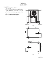
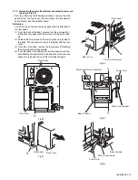
Страница 7: ...ttaching the side panel R on the back side and remove the screw A and B on the right side 2 Remove the three screws A attaching the side panel L on the back side and remove the screw A and B on the left side 3 Remove the side panel R and L backward Fig 1 Fig 2 Fig 3 A A Side panel R Side panel L A B Side panel R A B Side panel L ...

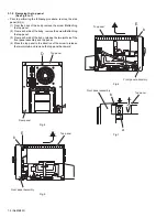
Страница 8: ... of the body remove the screw E attaching the top panel 3 From each side of the body release the two joints a of the front panel assembly and top panel 4 Move the top panel in the direction of the arrow to release the two joints b and remove the top panel backward Fig 4 Fig 5 Fig 6 Fig 7 D Top panel Rear panel E Front panel assembly Top panel b E Front panel assembly Top panel b b Front panel asse...

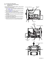
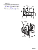
Страница 9: ...fier board 3 Disconnect the earth wire from the top of the CD changer mechanism cover and from the base chassis on each side of the body 4 From each side of the body remove the two screws F at taching the front panel assembly 5 From the bottom of the body remove the two screws G at taching the front panel assembly 6 Release the two joints d at the lower right and left sides of the body and remove ...

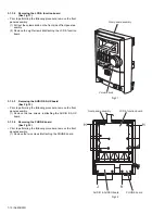
Страница 10: ...ig 11 3 1 3 3 Removing the AUDIO AUX board See Fig 12 Prior to performing the following procedure remove the front panel assembly 1 Remove the two screws J attaching the AUDIO AUX board 3 1 3 4 Removing the PHONE board See Fig 12 Prior to performing the following procedure remove the front panel assembly 1 Remove the two screws K attaching the PHONE board Fig 12 Volume konb Front panel assembly LC...

Страница 11: ...CN661 and CN681 on the main board and disconnect the wire from connector CN671 2 Remove the two screws M attaching the main board 3 Disconnect the connector CN501 and CN601 on the main board from the amplifier board while moving it in the direc tion of the arrow Fig 13 Fig 14 CN671 CN401 CN661 Main board CN402 CN681 Front panel assembly Rear panel M M CN601 CN501 Main board Amplifier board Rear pa...

Страница 12: ...moving the transformer board See Fig 16 Prior to performing the following procedure remove the side panel R L and the top panel 1 From the left side of the body disconnect the wire from connector CN102 on the amplifier board 2 Disconnect the wire from connector CN901 and CN902 on the transformer board 3 From the left side of the body remove the two screws P at taching the transformer board Fig 16 ...

Страница 13: ...edure remove the side panel R L the top panel and the transformer board 1 From the left side of the body disconnect the wire from connector CN105 on the amplifier board 2 From the back of the body remove the four screws Q at taching the fan Fig 17 Rear panel Fan Q Q Amplifier board CN105 ...

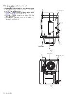
Страница 14: ...former board the tuner pack and the fan 1 From top of the body disconnect the wire from connector CN101 and CN204 on the amplifier board 2 From top of the body remove the five screws R attaching the amplifier board 3 From the back of the body remove the two screws T at taching the amplifier board Fig 18 Fig 19 CN101 CN204 Amplifier board R R Rear panel Rear panel Amplifier board T ...

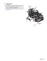
Страница 15: ...has sis 2 Release the two joints e at the lower right and left sides of the body The rear panel comes off together with the rear cover 3 From top of the body remove the four screws Y attaching the power transformer assembly 4 If you disconnect the power cord pull the power cord stop per attaching the power cord in the direction of the arrow as shown in Fig 24 and remove it from the base chassis Fi...

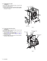
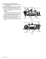
Страница 16: ...D changer mechanism cover fit the four point f of the CD changer mechanism cover to the four point g of the base chassis as shown in Fig 27 2 From the front side of the body remove the two screws B attaching the CD changer mechanism assembly 3 From the back of the body remove the two screws D at taching the CD changer mechanism assembly 4 Remove the CD changer mechanism assembly in the di rection ...

Страница 17: ... Fig 28 Fig 29 Fig 30 Point g Point f Point f Point g CD changer machanism cover Base chassis CD changer mechanism assembly Bracket B B CD changer mechanism assembly Bracket D D Bracket Bracket CD changer mechanism assembly ...

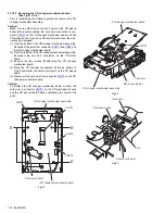
Страница 18: ...changer mechanism assembly disconnect the wire from connector on the CD motor board 3 Remove the four screws E attaching the CD changer mechanism board 4 Move the CD changer mechanism board as shown in Fig 32 and solder the short circuit point on the CD pickup board 5 Disconnect the card wire from connector CN701 on the CD changer mechanism board Caution To reattach the CD changer mechanism board ...

Страница 19: ... and CD changer mechanism board 1 Remove the three screws F attaching the CD changer mechanism holder The CD changer mechanism comes off too 2 Remove the four screws G attaching the CD changer mechanism Fig 34 Fig 35 CD changer mechanism assembly CD changer mechanism CD changer mechanism holder F F F CD changer mechanism CD changer mechanism holder G G G G ...

Страница 20: ...1 20 No MB353 SECTION 4 ADJUSTMENT This service manual does not describe ADJUSTMENT ...

Страница 21: ... No MB353 1 21 SECTION 5 TROUBLESHOOTING This service manual does not describe TROUBLESHOOTING ...

Страница 22: ... No MB353 AV MULTIMEDIA COMPANY AUDIO VIDEO SYSTEMS CATEGORY 10 1 1chome Ohwatari machi Maebashi city 371 8543 Japan Victor Company of Japan Limited VPT Printed in Japan ...

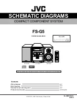
Страница 23: ... Printed circuit boards 2 1 2 3 2 7 2 13 to 23 CD ROM No SML200505 COMPACT COMPONENT SYSTEM No MB353SCH 2005 5 COPYRIGHT 2005 Victor Company of Japan Limited Area suffix J U S A C Canada CA FSG5 SP FSG5 SP FSG5 Lead free solder used in the board material Sn Ag Cu melting point 219 Centigrade ...

Страница 24: ...ponent parts appearing on the silk screen printed side parts side of the PWB diagrams the parts that are printed over with black such as the resistor diode and ICP or identified by the mark nearby are critical for safety ...

Страница 25: ... M E M O ...

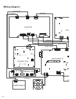
Страница 26: ...CN661 CN601 CN105 CN204 CN101 LC01 CN671 CN402 BI1206561V BI1206851V BI1206841V CN681 JK2 AMPLIFIER PCB LCD KEY PCB HP PCB FAN TUNER MODULE USB AUX PCB BI12P70100V BI1206821Y Board to Board Board to Board BI12P402341 Tra Fan motor wire Wiring diagram 2 1 ...

Страница 27: ...801 CN802 CN201 CN202 BN903 CD PCB CD MECH 5CD LDADER W CD MECH PICKUP L901 AC IN CN101 CN102 5 8 4 1 3 2 BI12P60170V V BI1206841V BI12P60170V PT PCB MAIN TRANSFORMER AMPLIFIER PCB BI1206561Y Board to Board ard Power cord Transformer wire Transformer wire 2 2 ...

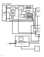
Страница 28: ...2H I O TRACKING COIL FOCUS COIL SPINDLE MOTOR FEED MOTOR TRP FOP TRVP SPOUT ANALOG OUTPUT SIL9226 AMP S5L9279 DRAM BACKUP MAIN PT SYSTEM MICO S3C825A LCD D KEY DISPLAY O P AC IN VOLTAGE SUPPLY PT PREMARY FUSE SUB TANS 1 5W MICON MN101C61G CD CONTROL BR93L56RF A B C D FWD REV E F LOADER ASS Y TRAY MOTOR Block diagram 2 3 ...

Страница 29: ... IC AUX IN USB IN 47K IMPEDANCE STK433_090 HP OUT 32 OHM IMPEDANCE 31V 70W X 2 AMP 5V REGULATOR L R CH VOLTAGE SUPPLY ST LED TUNER L TUNER R BND CEI DATA IN CLK1 DATA OUT D GND RDS CLK RDS DATA AHB PRO CONTROL VOLUME BD3881FV FUNCTION SW TAPE PRE_AMP TU L R USB L R AUX L R 6 OHM DISPLAY O P TU CONT 2 4 ...

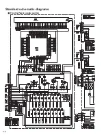
Страница 30: ...Standard schematic diagrams Front Power supply section 2 5 ...

Страница 31: ...Parts are safety assurance parts When replacing those parts make sure to use the specified one 2 6 ...

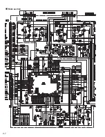
Страница 32: ...Main section 2 7 ...

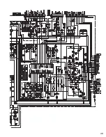
Страница 33: ...2 8 ...

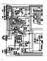
Страница 34: ...Amp section 2 9 ...

Страница 35: ...2 10 ...

Страница 36: ...CD section 2 11 ...

Страница 37: ...2 12 ...

Страница 38: ...Printed circuit boards Main board forward side Lead free solder used in the board material Sn Ag Cu melting point 219 C 2 13 ...

Страница 39: ... Cu melting point 219 Centigrade 2 14 ...

Страница 40: ...Main board reverse side Lead free solder used in the board material Sn Ag Cu melting point 219 Centigrad 2 15 ...

Страница 41: ...ng point 219 Centigrade 2 16 ...

Страница 42: ...Amp board forward side Lead free solder used in the board material Sn Ag Cu melting point 219 Centi 2 17 ...

Страница 43: ...solder used in the board material Sn Ag Cu melting point 219 Centigrade 2 18 ...

Страница 44: ...Amp board reverse side Lead free solder used in the board material Sn Ag Cu melting point 219 Centigrade 2 19 ...

Страница 45: ...in the board material Sn Ag Cu melting point 219 Centigrade 2 20 ...

Страница 46: ...CD board forward side Lead free solder used in the board material Sn Ag Cu melting point 219 Centigrade 2 21 ...

Страница 47: ...CD board reverse side Lead free solder used in the board material Sn Ag Cu melting point 219 Centigrade 2 22 ...

Страница 48: ...Trans board Lead free solder used in the board material Sn Ag Cu melting point 219 Centigrade 2 23 ...

Страница 49: ... M E M O ...

Страница 50: ...Victor Company of Japan Limited No MB353SCH Printed in Japan VPT AV MULTIMEDIA COMPANY AUDIO VIDEO SYSTEMS CATEGORY 10 1 1chome Ohwatari machi Maebashi city 371 8543 Japan ...

Страница 51: ...service parts Contents Exploded view of general assembly and parts list Block No M1 CD mechanism assembly and parts list Block No MB Electrical parts list Block No 01 06 Packing materials and accessories parts list Block No M3 FS G5 3 2 3 5 3 7 3 14 Area suffix J U S A C Canada MB353 ...

Страница 52: ...s board 9 8 7 10 6 5 11 12 65 1 4 3 2 64 62 62 62 65 2 2 53 56 56 56 52 51 57 58 50 50 59 60 60 2 2 60 2 2 47 48 49 46 16 13 14 15 13 19 20 21 2 2 2 2 2 2 2 18 17 17 23 66 F901 41 41 28 41 26 39 41 Block No M M M 1 A B B Dusb board CD board Dhp board Front board 67 ...

Страница 53: ...3 3 52 51 41 41 41 41 64 64 45 53 51 53 41 27 26 39 41 41 30 31 31 39 39 29 25 33 34 36 37 38 38 39 39 39 39 38 38 42 17 17 41 38 38 40 38 38 38 38 38 41 43 43 44 A Amp board Main board 54 ...

Страница 54: ...10101 HEATSINK 30 BI2029330101W1 HEAT RES BKT 31 BIBT0006091 TAPPING SCREW x2 33 BI2029000101W1 CD MECH COVER 34 BIZ25094901VV TUNER PACK 36 BI2400241V DC FAN DC12V 37 BI2028950101W1 REAR PLATE 38 BIRM000603S3 TAPPING SCREW x12 39 BIRT000617B3 TAPPING SCREW x11 40 BI1080799101V1 TRANS COVER 41 BIBT000604S3 TAPPING SCREW x14 42 BI2028970101W1 RIGHT PLATE 43 BIPMW001101S3 TAPPING SCREW x4 44 BI21104...

Страница 55: ...3 5 CD mechanism assembly and parts list Block No M M M B The parts without symbol number are not service 1 8 11 3 9 4 5 2 7 10 6 10 14 12 13 ...

Страница 56: ...0601G GEAR COVER 3 BIAJ6600601D GEAR A 4 BIAJ6600601B GEAR B 5 BIAJ6600601F GEAR C 6 BIAJ7000601A SHAFT 7 BISOHAAN PICK UP 8 BIAJ3100601B SPINDLE MOTOR 9 BIAJ3100601A FEED MOTOR 10 BIAJ6000601D SCREW M2XL3 x4 11 BI3409000174 LEAF SWITCH 12 BIAJ4100601E SUB PCB 13 BIAJ3700601A CONNECTOR 14 BIAJ7500601K TURN TABLE ...

Страница 57: ...F 50V C632 BICC822500KA042 C CAPACITOR 8200pF 50V C633 BICC101500JA041 C CAPACITOR 100pF 50V C634 BICC104500ZA043 C CAPACITOR 0 1uF 50V C635 BICC104500ZA043 C CAPACITOR 0 1uF 50V C636 BICE227100MP015 E CAPACITOR 220uF 10V C637 BICE107100MP015 E CAPACITOR 100uF 10V C641 BICM124101KP015 M CAPACITOR 0 12uF 100V C642 BICM124101KP015 M CAPACITOR 0 12uF 100V C643 BICE104500MP015 E CAPACITOR 0 1uF 50V C6...

Страница 58: ...5630105A005 C RESISTOR 56KΩ 1 10W R632 BIRC5630105A005 C RESISTOR 56KΩ 1 10W R633 BIRC1030105A005 C RESISTOR 10KΩ 1 10W R635 BIRC4720105A005 C RESISTOR 4 7KΩ 1 10W R636 BIRC4720085M000 C RESISTOR 4 7KΩ 1 8W R637 BIRC2210045M000 C RESISTOR 220Ω 1 4W R638 BIRC2210045M000 C RESISTOR 220Ω 1 4W R641 BIRC1020105A005 C RESISTOR 1KΩ 1 10W R642 BIRC1020085M000 C RESISTOR 1KΩ 1 8W R643 BIRC2020105A005 C RES...

Страница 59: ...W R381 BIRC1020105A005 C RESISTOR 1KΩ 1 10W R382 BIRC1010105A005 C RESISTOR 100Ω 1 10W R383 BIRC1010105A005 C RESISTOR 100Ω 1 10W R384 BIRC1010105A005 C RESISTOR 100Ω 1 10W R386 BIRC4730105A005 C RESISTOR 47KΩ 1 10W Symbol No Part No Part Name Description Local R391 BIRC2020105A005 C RESISTOR 2KΩ 1 10W R392 BIRC3020105A005 C RESISTOR 3KΩ 1 10W R393 BIRC3920105A005 C RESISTOR 3 9KΩ 1 10W R394 BIRC6...

Страница 60: ...41 C CAPACITOR 1000pF 50V C730 BICC222500KA042 C CAPACITOR 2200pF 50V C731 BICC333250KA042 C CAPACITOR 0 033uF 25V C732 BICC104250KA042 C CAPACITOR 0 1uF 25V C733 BICC104250KA042 C CAPACITOR 0 1uF 25V C734 BICC101500JA041 C CAPACITOR 100pF 50V C735 BICC101500JA041 C CAPACITOR 100pF 50V C736 BICC101500JA041 C CAPACITOR 100pF 50V C737 BICC101500JA041 C CAPACITOR 100pF 50V C738 BICC101500JA041 C CAPA...

Страница 61: ...7 BIRC1210085M000 C RESISTOR 120Ω 1 8W R878 BIRC1210085M000 C RESISTOR 120Ω 1 8W R879 BIRC1210085M000 C RESISTOR 120Ω 1 8W R880 BIRC1210085M000 C RESISTOR 120Ω 1 8W R881 BIRC1210085M000 C RESISTOR 120Ω 1 8W R882 BIRC1030105A005 C RESISTOR 10KΩ 1 10W R883 BIRC1030105A005 C RESISTOR 10KΩ 1 10W R884 BIRC1020085M000 C RESISTOR 1KΩ 1 8W R885 BIRC1020085M000 C RESISTOR 1KΩ 1 8W R886 BIRC1020105A005 C RE...

Страница 62: ...221500JA041 C CAPACITOR 220pF 50V C213 BICE107500MP015 E CAPACITOR 100uF 50V C214 BICE107500MP015 E CAPACITOR 100uF 50V C215 BICE476500MP015 CAPACITOR 47uF 50V C216 BICE476500MP015 CAPACITOR 47uF 50V C237 BICC104500KA042 C CAPACITOR 0 1uF 50V C238 BICC104500KA042 C CAPACITOR 0 1uF 50V C239 BICC104500KA042 C CAPACITOR 0 1uF 50V C240 BICC104500KA042 C CAPACITOR 0 1uF 50V C241 BICE106500MP015 E CAPAC...

Страница 63: ...V SOCKET 2 P CN201 BI12S150028V SOCKET 15P CN202 BI12S80058V SOCKET 8 P CN204 BI12S40047V SOCKET 4P JR101 BIRC0000085A003 C RESISTOR 0Ω 1 8W JR102 BIRC0000085A003 C RESISTOR 0Ω 1 8W JR103 BIRC0000085A003 C RESISTOR 0Ω 1 8W JR104 BIRC0000085A003 C RESISTOR 0Ω 1 8W JR105 BIRC0000085A003 C RESISTOR 0Ω 1 8W JR106 BIRC0000085A003 C RESISTOR 0Ω 1 8W JR107 BIRC0000085A003 C RESISTOR 0Ω 1 8W P103 BI11A050...

Страница 64: ... Packing materials and accessories parts list P6 P9 P10 P8 P2 P2 P7 P1 A8 A1A2A4 A1A2A3 A5 A6 A7 Block No M M M 3 No additional supplemental order of WARRANTY CARDs are available FS G5_J FS G5_C P3 P5 P4 A9 ...

Страница 65: ...281V AM LOOP ANT A 7 BIAN01022 ANT WIRE FM A 8 BI643FSG5050 REMOTE CONTROL A 9 BI644FSG5205SV SPEAKER BOX x2 P 1 BI430001809001W CARTON P 2 BI470011031001W POLY BAG I B P 3 BI470011057001W POLY BAG ANT LOOP P 4 BI4500113021W TOP CUSHION Speaker Box P 5 BI4500113031W BOTTOM CUSHION Speaker Box P 6 BI450012031000W FRONT CUSHION UNIT P 7 BI450012030000W REAR CUSHION UNIT P 8 BI4005355 POLY BAG for Re...

Отзывы: