


1-6 (No.49787B)
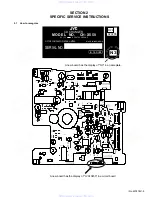
SECTION 3
DISASSEMBLY
• Perform operations according to the items to be disassembled.
Replacement of the pickup
(1) After removing the exterior (top and bottom).
(2) Proceed to the pickup replacement section.
(3) When applying grease, refer to the exploded view. Use
new grease.
Mechanism section
(1) Remove the exterior (required section only).
(2) The mechanism section is designed so that each unit
can be removed separately.
(3) When reassembling, refer to the assembling precau-
tions. (Use new grease when applying grease.)
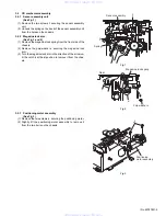
3.1
Exterior section
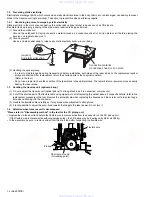
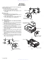
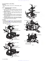
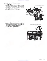
3.1.1
Removing the bottom cover and front panel assembly
(See Fig.1 to 4)
(1) Remove the two screw
A
to unlock the mounting direction
knob located on the side of the main unit.
(2) Turn the mounting direction knob in the direction of the ar-
row using a coin, etc. to remove it. (The knob can be re-
moved only when it is set to this position.)
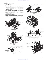
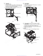
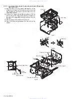
(3) Remove the four top cover fixing screws
B
at the triangle
marks on the side of the main unit. (Perform the same op-
eration on both sides.)
(4) Turn the unit upside down so the bottom surface is facing
upward.
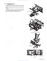
(5) Lift the rear edge of the bottom cover slightly and lift the
side by grasping the DIN jack section on the side panel,
then turn it toward the front (raise upward) to remove the
bottom cover.
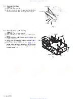
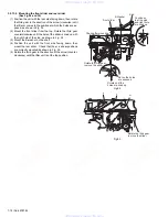
(6) Unhook the four catches located on both sides of the front
panel, and turn the front panel toward the top cover (lower
down) to remove the front panel.
Fig.1
Fig.2
Fig.3
Fig.4
Remove A and turn in
the direction of the arrow.
Bottom cover
Knob
Remove A and turn in
the direction of the arrow
B
B
A
B
B
Bottom cover
Knob
The front panel can be
separated by raising the cover.
Slightly lift the jack
section to remove.
Bottom cover
Unhook catches
Unhook catches
Front panel
www. xiaoyu163. com
QQ 376315150
9
9
2
8
9
4
2
9
8
TEL 13942296513
9
9
2
8
9
4
2
9
8
0
5
1
5
1
3
6
7
3
Q
Q
TEL 13942296513 QQ 376315150 892498299
TEL 13942296513 QQ 376315150 892498299