background image

SERVICE MANUAL

COPYRIGHT © 2005 Victor Company of Japan, Limited

No.YA080

2005/2

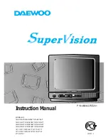
COLOUR TELEVISION

YA080

2005

2

AV-20RM4SE, 
AV-21RM4SE, 
AV-21RM4SN, 
AV-21RM4SP

TABLE OF CONTENTS

1

PRECAUTION. . . . . . . . . . . . . . . . . . . . . . . . . . . . . . . . . . . . . . . . . . . . . . . . . . . . . . . . . . . . . . . . . . . . . . . . .  1-3

2

SPECIFIC SERVICE INSTRUCTIONS . . . . . . . . . . . . . . . . . . . . . . . . . . . . . . . . . . . . . . . . . . . . . . . . . . . . . .  1-5

3

DISASSEMBLY  . . . . . . . . . . . . . . . . . . . . . . . . . . . . . . . . . . . . . . . . . . . . . . . . . . . . . . . . . . . . . . . . . . . . . . .  1-6

4

ADJUSTMENT . . . . . . . . . . . . . . . . . . . . . . . . . . . . . . . . . . . . . . . . . . . . . . . . . . . . . . . . . . . . . . . . . . . . . . .  1-11

5

TROUBLESHOOTING . . . . . . . . . . . . . . . . . . . . . . . . . . . . . . . . . . . . . . . . . . . . . . . . . . . . . . . . . . . . . . . . .  1-19

   RM-C1100


TV

[AV-21RM4]

Содержание AV-21RM4SP

Страница 1: ...pan Limited No YA080 2005 2 COLOUR TELEVISION YA080 2005 2 AV 20RM4SE AV 21RM4SE AV 21RM4SN AV 21RM4SP TABLE OF CONTENTS 1 PRECAUTION 1 3 2 SPECIFIC SERVICE INSTRUCTIONS 1 5 3 DISASSEMBLY 1 6 4 ADJUSTMENT 1 11 5 TROUBLESHOOTING 1 19 RM C1100TV AV 21RM4 ...

Страница 2: ... 33 4MHz 5 5MHz B G 32 4MHz 6 5MHz L Colour Sub Carrier Frequency PAL SECAM NTSC 4 43MHz 4 40625MHz 4 25MHz 3 58MHz 4 43MHz Power Input AC220V AC240V 50Hz Power Consumption 85W Max 4W Standby 85W Max 3W Standby Aerial Input Terminal 75Ω unbalanced coaxial Picture Tube Size Visible size 48cm 20 Measured diagonally H 41 2cm V 31 2cm Visible size 51cm 21 Measured diagonally H 41 6cm V 31 5cm High Vol...

Страница 3: ...replacements or alternatives approved by the manufacturer of the complete product 7 Do not check high voltage by drawing an arc Use a high voltage meter or a high voltage probe with a VTVM Discharge the picture tube before attempting meter connection by connecting a clip lead to the ground frame and connecting the other end of the lead through a 10kΩ 2W resistor to the anode button 8 When service ...

Страница 4: ...aracteristics are identified in the Parts List of Service Manual Electrical components having such features are identified by shading on the schematics and by on the Parts List in the Service Manual The use of a substitute replacement which does not have the same safety characteristics as the recommended replacement part shown in the Parts List of Service Manual may cause shock fire or other hazar...

Страница 5: ...161048 VE 20161045 VE 20161041 TV RF System B G D K B G B G L Colour System TV mode PAL SECAM PAL PAL SECAM TV RF System B G D K B G B G L Pin No Signal designation Matching value EXT 1 1 AUDIO R output 500mV rms Nominal Low impedance Used TV OUT 2 AUDIO R input 500mV rms Nominal High impedance Used R1 3 AUDIO L output 500mV rms Nominal Low impedance Used TV OUT 4 AUDIO GND Used 5 GND B Used 6 AUD...

Страница 6: ...JACK PWB Remove the REAR COVER Remove the MAIN PWB 1 Remove the 1 screw D 2 Remove the HEADPHONE JACK PWB 3 1 6 CHECKING THE PW BOARD To check the back side of the PW Board 1 Pull out the PW Board Refer to REMOVING THE MAIN PWB 2 Erect the PW Board vertically so that you can easily check the back side of the PWB CAUTION When erecting the PW Board be careful so that there will be no contacting with...

Страница 7: ... No YA080 1 7 A B C MAIN PWB FRONT AV JACK PWB HEADPHONE JACK PWB FUNCTION BUTTON SPEAKER FRONT CABINET BACK COVER PICTURE TUBE CRT SOCKET PWB Within MAIN PWB x6 x4 x2 D x1 ...

Страница 8: ...7 2 5 key on the remote control unit or press MUTING key and INFORMATION key at the simultaneously 2 The SERVICE MENU screen of Fig 1 will be displayed 3 Verify what to set in the SERVICE MENU and set whatever is necessary Fig 1 Refer to the SERVICE ADJUSTMENT for setting 4 Press the STANDARD key to exit SERVICE MENU 5 Receive channel setting Refer to the OPERATING INSTRUCTIONS USER S GUIDE and se...

Страница 9: ... service mode NOTE DO NOT TURN OFF THE TV BY USING POWER BUTTON ON THE FRONT PANEL Setting item Setting value Setting item Setting value PICTURE MENU INSTALL BRIGHTNESS These adjust are automatically restored when APS bit in service menu is set The procedure for setting APS bit is described below PROGRAMME Refer to the INSTRUCTION BOOK CONTRAST BAND COLOUR CHANNEL SHARPNESS SEARCH HUE only NTSC FI...

Страница 10: ...he tweezers and remove the chip part Transistors diodes variable resistors etc 1 Apply extra solder to each lead 2 As shown in the figure push the part with tweezers and alternately melt the solder at each lead Shift and remove the chip part NOTE After removing the part remove remaining solder from the pattern 2 How to install Chip parts Resistors capacitors etc 1 Apply solder to the pattern as in...

Страница 11: ...6 Never touch any adjustment parts which are not specified in the list for this adjustment variable resistors transformers condensers etc 7 Presetting before adjustment Unless otherwise specified in the adjustment instructions preset the following functions with the remote control unit 4 2 ADJUSTMENT EQUIPMENT 1 DC voltmeter or digital voltmeter 2 Signal generator Pattern generator PAL SECAM NTSC ...

Страница 12: ...enu appears Fig 3 3 Press the key and select the adjustment item 4 Press the key and set the setting value Fig 3 MENU MENU SCREEN SOUND PICTURE FEATURE INSTALL PROGRAM ADJUSTMENT ITEM SETTING VALUE JVCAK30 37 B20 SERVICE MENU OSD IF1 IF2 IF3 IF4 AGC VLIN RGBH VSOF VPOF 1 1 AVL GEOMETRY GEOMETRY MENU VSIZ VPOS VSCO VCCO HSIZ HPOS HPIN AUTO ADJUSTMENT ITEM SETTING VALUE FUNCTION Key AV Key INFORMATI...

Страница 13: ...P1 FM PRESCALER WHEN AVL IS OFF NIP1 NICAM PRESCALER WHEN AVL IS OFF SCP1 SCART PRESCALER WHEN AVL IS OFF SEC1 SECAM PRESCALER WHEN AVL IS OFF FMP2 FM PRESCALER WHEN AVL IS ON NIP2 NICAM PRESCALER WHEN AVL IS ON SCP2 SCART PRESCALER WHEN AVL IS ON SEC2 SECAM PRESCALER WHEN AVL IS ON F1H HIGH BYTE OF VHF1 VHF3 CROSS OVER FREQUENCY F1L LOW BYTE OF VHF1 VHF3 CROSS OVER FREQUENCY F2H HIGH BYTE OF VHF3...

Страница 14: ...CE MODE 2 Press the YELLOW key to disable vertical scan 3 Adjust SCREEN VR on the FBT as thin as possible 4 Press YELLOW key again to enable vertical scan 5 Press STANDARD key to leave service menu FBT FOCUS VR SCREEN VR Item Measuring instrument Test point Adjustment part Description OSD HORIZONTAL POSITION adjustment Remote control unit OSD 1 Enter the SERVICE MODE 2 Select OSD with the key 3 Ad...

Страница 15: ...ith the key 4 Press BLUE key 5 The adjustment will be done automatically by software 6 See the AGC indicator on SERVICE MENU it must be 1 7 Check that picture is normal at 90dBµV signal level Item Measuring instrument Test point Adjustment part Description VERTICAL SIZE OFFSET 60Hz adjustment Signal generator Remote control unit VSOF 1 Receive a NTSC crosshatch pattern of vertical frequency 60Hz 2...

Страница 16: ...e pattern is horizontally centered E F 5 Check and readjust a horizontal position item if the adjustment becomes improper after some other geometric adjustments are done Press the MENU key and memorize the set value VERTICAL SIZE 50Hz adjustment Signal generator Remote control unit VSIZ 1 Receive a PAL crosshatch pattern of vertical frequency 50Hz 2 Enter the SERVICE MODE 3 Press the GREEN key to ...

Страница 17: ...nal generator Remote control unit HPOS 1 Receive a PAL circle pattern signal of vertical frequency 50Hz 2 Enter the GEOMETRY MODE 3 Select HPOS Horizontal position with the key 4 Adjust HPOS with the key until the circle pattern is horizontally centered C D 5 Check and readjust HPOS item if the adjustment becomes improper after some other geometric adjustments are done VERTICAL LINEARITY adjustmen...

Страница 18: ...rument Test point Adjustment part Description A B Item Measuring instrument Test point Adjustment part Description WHITE BALANCE Low light adjustment Signal generator Remote control unit WR WG WB 1 Receive a black white signal colour off 2 Enter the SERVICE MODE 3 Select WR WG WB with the key respectively 4 Adjust WR WG WB with the key respectively until the white part turns to pure white without ...

Страница 19: ... No YA080 1 19 SECTION 5 TROUBLESHOOTING This service manual does not describe TROUBLESHOOTING ...

Страница 20: ... No YA080 AV MULTIMEDIA COMPANY VIDEO DISPLAY CATEGORY 12 3 chome Moriya cho kanagawa ku Yokohama kanagawa prefecture 221 8528 Japan Victor Company of Japan Limited VPT Printed in Japan ...

Страница 21: ...20161045 VE 20161041 VE 20161048 AV 21RM4SN AV 21RM4SP AV 21RM4SE VE 20166161 VE 20165426 VE 20161051 AV 20RM4SE CONTENTS BLOCK DIAGRAM CIRCUIT DIAGRAMS MAIN PWB CIRCUIT DIAGRAM HEADPHONE JACK PWB CIRCUIT DIAGRAM FRONT AV JACK PWB CIRCUIT DIAGRAM PATTERN DIAGRAMS MAIN PWB PATTERN HEADPHONE JACK PWB PATTERN FRONT AV JACK PWB PATTERN 2 3 2 5 2 18 2 19 2 21 2 23 2 24 ...

Страница 22: ...2 2 No YA080 ...

Страница 23: ...ONTROLLER IC501 IC500 MEMORY I2 C SERVICE CONNECTOR EEPROM KEYPAD IR SENSOR AC IN HP AMP IC701 AUDIO AMP IC401 MONO L R SMPS IC800 12V 8V 5V 5V STBY VIDEO SWITCHING CIRCUITS IF SCART1 FAV HOR DRIVE Q603 VER AMP IC600 RGB AMP IC900 FBT TR601 VER DEFL HOR DEFL AUDIO OUT BLOCK DIAGRAM ...

Страница 24: ... No YA080 2 5 2 6 No YA080 MAIN PWB ASS Y 1 7 VE 20161045 AV 21RM4SN VE 20161041 AV 21RM4SP VE 20161048 AV 21RM4SE VE 20161051 AV 20RM4SE CIRCUIT DIAGRAMS MAIN PWB CIRCUIT DIAGRAM 1 7 ...

Страница 25: ...2 8 No YA080 No YA080 2 7 MAIN PWB ASS Y 2 7 VE 20161045 AV 21RM4SN VE 20161041 AV 21RM4SP VE 20161048 AV 21RM4SE VE 20161051 AV 20RM4SE MAIN PWB CIRCUIT DIAGRAM 2 7 ...

Страница 26: ... No YA080 2 9 2 10 No YA080 MAIN PWB ASS Y 3 7 VE 20161045 AV 21RM4SN VE 20161041 AV 21RM4SP VE 20161048 AV 21RM4SE VE 20161051 AV 20RM4SE MAIN PWB CIRCUIT DIAGRAM 3 7 ...

Страница 27: ...2 12 No YA080 No YA080 2 11 FBT MAIN PWB ASS Y 4 7 VE 20161045 AV 21RM4SN VE 20161041 AV 21RM4SP VE 20161048 AV 21RM4SE VE 20161051 AV 20RM4SE MAIN PWB CIRCUIT DIAGRAM 4 7 ...

Страница 28: ... No YA080 2 13 2 14 No YA080 POWER REG SW TRANSFORMER MAIN PWB ASS Y 5 7 VE 20161045 AV 21RM4SN VE 20161041 AV 21RM4SP VE 20161048 AV 21RM4SE VE 20161051 AV 20RM4SE MAIN PWB CIRCUIT DIAGRAM 5 7 ...

Страница 29: ...2 16 No YA080 No YA080 2 15 MAIN PWB ASS Y 6 7 VE 20161045 AV 21RM4SN VE 20161041 AV 21RM4SP VE 20161048 AV 21RM4SE VE 20161051 AV 20RM4SE MAIN PWB CIRCUIT DIAGRAM 6 7 ...

Страница 30: ... No YA080 2 17 2 18 No YA080 MAIN PWB ASS Y 7 7 VE 20161045 AV 21RM4SN VE 20161041 AV 21RM4SP VE 20161048 AV 21RM4SE VE 20161051 AV 20RM4SE MAIN PWB CIRCUIT DIAGRAM 7 7 ...

Страница 31: ...2 20 No YA080 No YA080 2 19 HEADPHONE JACK PWB VE 20165426 FRONT AV JACK PWB VE 20166161 FRONT AV JACK PWB CIRCUIT DIAGRAM HEADPHONE JACK PWB CIRCUIT DIAGRAM ...

Страница 32: ... No YA080 2 21 2 22 No YA080 FRONT TOP PATTERN DIAGRAMS MAIN PWB PATTERN CRT SOCKET PWB PATTERN Within MAIN PWB ...

Страница 33: ... No YA080 2 23 TOP HEADPHONE JACK PWB PATTERN ...

Страница 34: ...2 24 No YA080 TOP FRONT AV JACK PWB PATTERN ...

Страница 35: ... AV 21RM4SE 3 7 MAIN P W BOARD ASS Y VE 20161048 3 7 PRINTED WIRING BOARD PARTS LIST AV 21RM4SN 3 10 MAIN P W BOARD ASS Y VE 20161045 3 10 PRINTED WIRING BOARD PARTS LIST AV 21RM4SP 3 13 MAIN P W BOARD ASS Y VE 20161041 3 13 PACKING PARTS LIST 3 16 PACKING 3 17 USING P W BOARD REMOTE CONTROL UNIT P W B ASS Y name AV 20RM4SE AV 21RM4SE AV 21RM4SN AV 21RM4SP MAIN P W B with CRT SOCKET P W B VE 20161...

Страница 36: ...20165670 LABEL 13 VE 30029498 POWERCORD 2 2MT 14 VE 20004520 CABLE HOLDER 15 VE 20004646 FOOT RUBBER x2 Ref No Part No Part Name Description Local V01 VE 30002749 PICTURE TUBE ITC Inc DY PC MAGNET L01 VE 30002124 DEG COIL EARTH CB TR601 VE 30017788 TRF FBT within MAIN PWB 1 VE 20160402 BUTTON ON OFF 2 VE 35000013 SPRING ON OFF SWITCH 3 VE 20053831 LENS PRE AMP 4 VE 20167108 LENS 5 VE 20056446 LENS...

Страница 37: ... No YA080 3 3 EXPLODED VIEW x6 HEADPHONE JACK PWB FRONT AV JACK PWB CRT SOCKET PWB within MAIN PWB 1 2 4 6 3 8 15 7 14 10 13 12 11 5 9 L01 V01 TR601 MAIN PWB ...

Страница 38: ...P SMD 100PF 50V J C159 VE 30012560 CAP SMD 100PF 50V J C160 VE 30000387 CAP EL 33UF 50V M C166 VE 30012559 CAP SMD 10PF 50V D C201 VE 30000400 CAP EL 47UF 50V M C205 VE 30000371 CAP EL 22UF 50V M C206 VE 30012610 CAP SMD 10NF 50V J C207 VE 30012610 CAP SMD 10NF 50V J C300 VE 30000400 CAP EL 47UF 50V M C302 VE 30000092 CAP MKT 220NF 63V J C408 VE 30012586 CAP SMD 22NF 50V K C409 VE 30000345 CAP EL ...

Страница 39: ...VE 30012695 RES SMD 1 16W 470R J R127 VE 30000459 RES CF 1 4W 100R J Ref No Part No Part Name Description Local R128 VE 30000471 RES CF 1 4W 10K J R129 VE 30012713 RES SMD 1 16W 75R J R130 VE 30000594 RES CF 1 4W 22K J R132 VE 30000723 RES CF 1 4W 47K J R133 VE 30000718 RES CF 1 4W 4 7K J R135 VE 30012657 RES SMD 1 16W 1K J R153 VE 30012657 RES SMD 1 16W 1K J R201 VE 30012674 RES SMD 1 16W 27K J R...

Страница 40: ...6W 22K J R835 VE 30016802 RES WW 5W 5 6R J RAD R900 VE 30006712 FERRITE BEAD R901 VE 30006712 FERRITE BEAD R902 VE 30006712 FERRITE BEAD R903 VE 30000525 RES CF 1 2W 1 5K J R904 VE 30000525 RES CF 1 2W 1 5K J R905 VE 30000525 RES CF 1 2W 1 5K J R906 VE 30000525 RES CF 1 2W 1 5K J R919 VE 30001213 RES FUSE 1 4W 1R J J107 VE 30000683 RES CF 1 4W 390R J J108 VE 30000712 RES CF 1 4W 470R J J271 VE 300...

Страница 41: ...P EL 22UF 50V M C206 VE 30012610 CAP SMD 10NF 50V J C207 VE 30012610 CAP SMD 10NF 50V J C300 VE 30000400 CAP EL 47UF 50V M C302 VE 30000092 CAP MKT 220NF 63V J C408 VE 30012586 CAP SMD 22NF 50V K C409 VE 30000345 CAP EL 10UF 50V M C410 VE 30000384 CAP EL 2 2UF 50V M C411 VE 30000345 CAP EL 10UF 50V M C412 VE 30012586 CAP SMD 22NF 50V K C413 VE 30000362 CAP EL 1UF 50V M C414 VE 30012585 CAP SMD 2 2...

Страница 42: ...0000718 RES CF 1 4W 4 7K J R135 VE 30012657 RES SMD 1 16W 1K J Ref No Part No Part Name Description Local R153 VE 30012657 RES SMD 1 16W 1K J R201 VE 30012674 RES SMD 1 16W 27K J R202 VE 30012692 RES SMD 1 16W 4 7K J R204 VE 30000459 RES CF 1 4W 100R J R206 VE 30000459 RES CF 1 4W 100R J R301 VE 30000471 RES CF 1 4W 10K J R302 VE 30000471 RES CF 1 4W 10K J R303 VE 30012641 RES SMD 1 16W 10K J R305...

Страница 43: ...R819 VE 30000466 RES CF 1 4W 1K J R821 VE 30000470 RES CF 1 2W 10K J R828 VE 30001260 RES WW 5W 2 2R J R829 VE 30000718 RES CF 1 4W 4 7K J R830 VE 30012657 RES SMD 1 16W 1K J R831 VE 30012669 RES SMD 1 16W 22K J R835 VE 30016802 RES WW 5W 5 6R J RAD R900 VE 30000712 RES CF 1 4W 470R J R901 VE 30000712 RES CF 1 4W 470R J R902 VE 30000712 RES CF 1 4W 470R J R903 VE 30000525 RES CF 1 2W 1 5K J R904 V...

Страница 44: ... C159 VE 30012560 CAP SMD 100PF 50V J C160 VE 30000387 CAP EL 33UF 50V M C166 VE 30012559 CAP SMD 10PF 50V D COG C201 VE 30000400 CAP EL 47UF 50V M C205 VE 30000371 CAP EL 22UF 50V M C206 VE 30012610 CAP SMD 10NF 50V J C207 VE 30012610 CAP SMD 10NF 50V J C300 VE 30000400 CAP EL 47UF 50V M C302 VE 30000092 CAP MKT 220NF 63V J C408 VE 30012586 CAP SMD 22NF 50V K C409 VE 30000345 CAP EL 10UF 50V M C4...

Страница 45: ...VE 30000459 RES CF 1 4W 100R J R128 VE 30000471 RES CF 1 4W 10K J Ref No Part No Part Name Description Local R129 VE 30012713 RES SMD 1 16W 75R J R130 VE 30000594 RES CF 1 4W 22K J R132 VE 30000723 RES CF 1 4W 47K J R133 VE 30000718 RES CF 1 4W 4 7K J R135 VE 30012657 RES SMD 1 16W 1K J R153 VE 30012657 RES SMD 1 16W 1K J R201 VE 30012674 RES SMD 1 16W 27K J R202 VE 30012692 RES SMD 1 16W 4 7K J R...

Страница 46: ...W 10R J R817 VE 30001037 RES MF 1 4W 99K F R818 VE 30000925 RES MF 1 4W 2 2K F R819 VE 30000466 RES CF 1 4W 1K J R821 VE 30000470 RES CF 1 2W 10K J R828 VE 30001260 RES WW 5W 2 2R J R829 VE 30000718 RES CF 1 4W 4 7K J R830 VE 30012657 RES SMD 1 16W 1K J R831 VE 30012669 RES SMD 1 16W 22K J R835 VE 30016802 RES WW 5W 5 6R J RAD R900 VE 30000712 RES CF 1 4W 470R J R901 VE 30000712 RES CF 1 4W 470R J...

Страница 47: ...UF 50V M C143 VE 30012583 CAP SMD 1 5NF 50V K C144 VE 30012583 CAP SMD 1 5NF 50V K C145 VE 30012589 CAP SMD 4 7NF 50V K C155 VE 30012560 CAP SMD 100PF 50V J C159 VE 30012560 CAP SMD 100PF 50V J C160 VE 30000387 CAP EL 33UF 50V M C166 VE 30012559 CAP SMD 10PF 50V D COG C201 VE 30000400 CAP EL 47UF 50V M C205 VE 30000371 CAP EL 22UF 50V M C206 VE 30012610 CAP SMD 10NF 50V J C207 VE 30012610 CAP SMD ...

Страница 48: ...J R115 VE 30012713 RES SMD 1 16W 75R J R116 VE 30012987 RES SMD 1 16W 56R J Ref No Part No Part Name Description Local R117 VE 30012713 RES SMD 1 16W 75R J R118 VE 30000792 RES CF 1 4W 75R J R122 VE 30000792 RES CF 1 4W 75R J R123 VE 30000792 RES CF 1 4W 75R J R125 VE 30012657 RES SMD 1 16W 1K J R126 VE 30012695 RES SMD 1 16W 470R J R127 VE 30000459 RES CF 1 4W 100R J R128 VE 30000471 RES CF 1 4W ...

Страница 49: ...982 RES MF 1 4W 4 7K J R807 VE 30001159 RES MO 1W 0 33R J R809 VE 30007784 RES MO 5W 33K J R810 VE 30001257 RES MG 1 2W 4 7M J R811 VE 30000594 RES CF 1 4W 22K J R813 VE 30000718 RES CF 1 4W 4 7K J R814 VE 30012662 RES SMD 1 16W 2 7K J R815 VE 30000452 RES CF 1 4W 10R J R817 VE 30001037 RES MF 1 4W 99K F R818 VE 30000925 RES MF 1 4W 2 2K F R819 VE 30000466 RES CF 1 4W 1K J R821 VE 30000470 RES CF ...

Страница 50: ...Part Name Description Local 1 VE 50052502 CARTON BOX AV 21RM4SN 1 VE 50052504 CARTON BOX AV 21RM4SP 1 VE 50052499 CARTON BOX AV 21RM4SE 2 VE 20155640 SNOW BOX ASSY 4pcs in 1set 3 VE 50027456 POLY BAG 1700 1000 4 VE 70000587 POLY BAG 5 VE 30017763 REMOTE CONTROL UNIT RM C1100 6 VE 50052501 INST BOOK Eng Fin Fre Ger Ita Nor Por Spa Swe Dan Dut AV 21RM4SN 6 VE 50052453 INST BOOK Eng Dut Fre Ger Ita P...

Страница 51: ... No YA080 3 17 PACKING 1 3 8 2 2 4 5 6 7 9 ...

Отзывы: