

OCX1100-48SX Switch Quick Start
See the complete OCX Series documentation at
www.juniper.net/techpubs/en_US/release-independent/junos/
information-products/pathway-pages/ocx-series/product/ .
To install and perform initial configuration of a Juniper Networks
®
OCX1100-48SX Switch, you need:
z
An electrostatic discharge (ESD) grounding strap (not provided)
z
One pair of front rack-mounting brackets (provided)
z
One pair of rack-mounting slider brackets (provided)
z
Eight Phillips-head front rack-mounting bracket screws (provided)
z
Eight rack-mounting screws (not provided)
z
One screwdriver appropriate for your rack-mounting screws (not provided)
z
Two AC power cords for AC powered switch models (with plugs appropriate for your
geographical location) or two DC powers cords for DC powered switch models
z
RJ-45 cable and RJ-45 to DB-9 serial port adapter (provided)
z
USB2.0 AF-MICOR AM 150MM BLK cable (provided)
z
Management host, such as a PC, with an Ethernet port (not provided)
Register product serial numbers on the Juniper Networks website at
https://tools.juniper.net/svcreg/SRegSerialNum.jsp and update the installation base data
at https://www.juniper.net/customers/csc/management/updateinstallbase.jsp if there is
any addition or change to the installation base or if the installation base is moved.
Juniper Networks will not be accountable for not meeting the hardware replacement
service-level agreement for products that do not have registered serial numbers or
accurate installation base data.
WARNING:
Ensure that you understand how to prevent ESD damage. Attach the
ESD grounding strap to your bare wrist, and connect the strap to the ESD point on
the chassis.
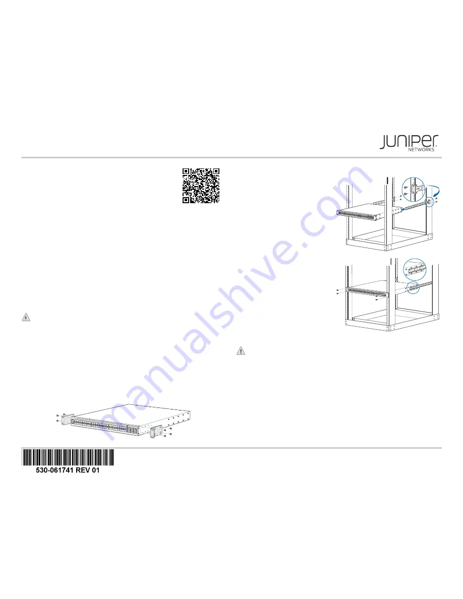
Part 1: Mount the Switch on Four Posts of a Rack
You can mount the switch on four posts of a 19-in. rack or cabinet by using the
rack-mounting brackets provided with the switch. Two persons are required for this
procedure.
1. Place the rack or cabinet in its permanent location, allowing adequate clearance for
airflow and maintenance, and secure it to the building structure.
NOTE:
While mounting multiple units on a rack, mount the heaviest unit at the bottom
and mount the other units from the bottom to the top in decreasing order of weight.
2. Align the holes on the front rack-mounting bracket with the screw holes on the side of
the chassis and attach the front rack-mounting bracket to the switch by using the front
rack-mounting bracket screws.
NOTE:
Installing the switch requires one person to lift it and a second person to secure it
to the rack.
3. Align the holes on the rack-mounting
slider bracket with the screw holes
on the back of the rack posts.
4. Attach the rack-mounting slider
brackets to the rack posts by using
rack-mounting screws. The ears of
the bracket must be facing backward
and outward.
5. Position the switch so that the
rack-mounting slider brackets align
horizontally within the two rows of
rack-mounting slider bracket pegs
located on the side panel of the
switch.
6. Slide the switch backwards so that
the rack-mounting slider brackets fit
into the space between the two rows
of rack-mounting slider pegs.
7. Have a second person secure the
front rack-mounting brackets to the
front of the rack posts by using
rack-mounting screws. Tighten the
screws.
8. Ensure that the switch chassis is
level by verifying that all the screws
on the front of the rack are aligned
with the screws on the back of the
rack.
Part 2: Connect Power to the Switch
CAUTION:
Do not mix or install:
z
AC and DC power supplies in the same chassis.
z
Power supplies and fan modules with different airflow labels (AIR IN (AFI) and AIR
OUT (AFO)) in the same chassis.
The switch is shipped with power supplies pre-installed, either AC or DC, depending on
the switch model.
1. If the power source outlet has a power switch, set it to the OFF (0) position.
2. Insert the coupler end of the power cord into the power port of the power supply
module.
3. Connect the power cord plug into the power source outlet.
4. If the power source outlet has a power switch, set it to the ON (|) position.
g00066
5
g000666
g00066
7


