Replacing and Troubleshooting Hardware Components
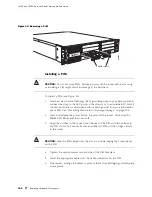
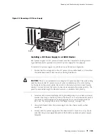
Installing the USB Storage Device
To install the USB storage device:
NOTE:
For a list of supported USB storage devices, see the
J-series Services Router
Release Notes
at
http://www.juniper.net
.
1.
Attach an electrostatic discharge (ESD) grounding strap to your bare wrist and
connect the strap to the ESD point on the chassis, or to an outside ESD point if
the router is disconnected from earth ground. For more information about
ESD, see “Preventing Electrostatic Discharge Damage” on page 205.
2.
Orient the USB storage device with the USB port on the front panel of the router.
3.
Insert the USB storage device into the USB port. If the USB storage device does
not easily slide into the port, it might not be oriented correctly. Turn the USB
storage device upside-down and try again.
4.
To configure the USB storage device with the
request system snapshot
command,
see the
J-series Services Router Administration Guide
.
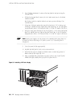
Removing and Installing DRAM Modules
The DRAM installed on the Routing Engine provides storage for the routing and
forwarding tables and for other Routing Engine processes. The design of the
Routing Engine allows you to modify the DRAM configuration by adding DRAM
modules to the Routing Engine board, or removing DRAM modules from the board.
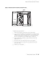
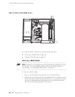
The DRAM modules are located on the top of the Routing Engine, as shown in
Figure 45.
NOTE:
Use only DRAM modules purchased through Juniper Networks specifically
for your model. Also, DRAM modules are not always transferable across J-series
platforms. You can use the same DRAM module in both the J4350 and J6350
Services Routers. However, do not use a DRAM from another J-series platform
in a J4350 or J6350 router.
Replacing Hardware Components
155
Содержание J4350
Страница 14: ...J4350 and J6350 Services Router Getting Started Guide xiv Table of Contents...
Страница 22: ...2 J series Overview...
Страница 68: ...J4350 and J6350 Services Router Getting Started Guide 48 Field Replaceable PIMs...
Страница 75: ...Services Router User Interface Overview Figure 25 J Web Layout Using the J Web Interface 55...
Страница 88: ...J4350 and J6350 Services Router Getting Started Guide 68 Using the Command Line Interface...
Страница 90: ...70 Installing a Services Router...
Страница 100: ...J4350 and J6350 Services Router Getting Started Guide 80 Site Preparation Checklist...
Страница 112: ...J4350 and J6350 Services Router Getting Started Guide 92 Powering a Services Router On and Off...
Страница 144: ...J4350 and J6350 Services Router Getting Started Guide 124 Verifying Secure Web Access...
Страница 160: ...J4350 and J6350 Services Router Getting Started Guide 140 Verifying J series License Management...
Страница 162: ...142 Maintaining Services Router Hardware...
Страница 194: ...J4350 and J6350 Services Router Getting Started Guide 174 Troubleshooting Hardware Components...
Страница 202: ...J4350 and J6350 Services Router Getting Started Guide 182 Packing a Router or Component for Shipment...
Страница 204: ...184 J series Requirements and Specifications...
Страница 220: ...J4350 and J6350 Services Router Getting Started Guide 200 ISDN RJ 45 Connector Pinout...
Страница 267: ...Part 5 Index Index 247...
Страница 268: ...248 Index...

