Installing and Connecting a Services Router
c.
With a Phillips screwdriver, remove the screws and washers from the PEM
nuts at the grounding point on the rear of the chassis.
d.
Place the grounding lug at the other end of the cable over the grounding
point, as shown in Figure 34.
e.
Secure the cable lug to the grounding point, first with the washers, then
with the screws.
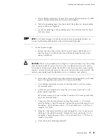
NOTE:
A DC power supply in a Services Router becomes grounded when you
connect a grounding cable between the router and earth ground.
3.
For each power supply:
a.
Ensure that the voltage across the DC power source cable leads is 0 V
and that there is no chance that the cable leads might become active
during installation.
CAUTION:
There is no standard color coding for DC power cables. The color coding
used by the external DC power source at your site determines the color coding
for the leads on the power cables that attach to the terminal studs on each power
supply. You must ensure that power connections maintain the proper polarity. The
power source cables might be labeled
(+)
and
(–)
to indicate their polarity.
b.
Verify that a licensed electrician has attached the appropriate power cable
lugs to the negative and positive DC source power cables.
c.
Use a Phillips screwdriver to remove the clear plastic cover protecting
the terminal block.
d.
Within the terminal block, remove the two center screws next to the
labels
–48 VDC
and
RTN
.
Each screw contains a captive washer to secure a DC source power cable
lug to the terminal block.
e.
Using one of the removed screws, secure the positive (+) DC source
power cable lug to the
RTN
terminal. Tighten the screw until snug. Do not
overtighten. Apply between 8 lb-in. (0.9 Nm) and 9 lb-in. (1.02 Nm) of
torque to the screw.
f.
Using the other removed screw, secure the negative (–) DC source power
cable lug to the
–48 VDC
terminal. Tighten the screw until snug. Do not
overtighten. Apply between 8 lb-in. (0.9 Nm) and 9 lb-in. (1.02 Nm) of
torque to the screw.
g.
Dress the power cables appropriately.
Connecting Power
89
Содержание J4350
Страница 14: ...J4350 and J6350 Services Router Getting Started Guide xiv Table of Contents...
Страница 22: ...2 J series Overview...
Страница 68: ...J4350 and J6350 Services Router Getting Started Guide 48 Field Replaceable PIMs...
Страница 75: ...Services Router User Interface Overview Figure 25 J Web Layout Using the J Web Interface 55...
Страница 88: ...J4350 and J6350 Services Router Getting Started Guide 68 Using the Command Line Interface...
Страница 90: ...70 Installing a Services Router...
Страница 100: ...J4350 and J6350 Services Router Getting Started Guide 80 Site Preparation Checklist...
Страница 112: ...J4350 and J6350 Services Router Getting Started Guide 92 Powering a Services Router On and Off...
Страница 144: ...J4350 and J6350 Services Router Getting Started Guide 124 Verifying Secure Web Access...
Страница 160: ...J4350 and J6350 Services Router Getting Started Guide 140 Verifying J series License Management...
Страница 162: ...142 Maintaining Services Router Hardware...
Страница 194: ...J4350 and J6350 Services Router Getting Started Guide 174 Troubleshooting Hardware Components...
Страница 202: ...J4350 and J6350 Services Router Getting Started Guide 182 Packing a Router or Component for Shipment...
Страница 204: ...184 J series Requirements and Specifications...
Страница 220: ...J4350 and J6350 Services Router Getting Started Guide 200 ISDN RJ 45 Connector Pinout...
Страница 267: ...Part 5 Index Index 247...
Страница 268: ...248 Index...


