background image

– 1 –

ESP

AÑOL

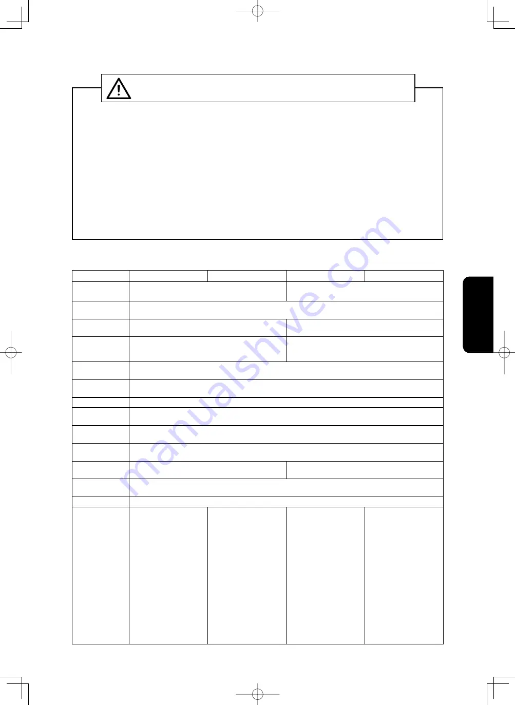
ESPECIFICACIONES

Modelo

MH-481

MH-481-4/-5

MH-484

MH-484-4/-5

Tipo de costura Maquina de puntada de cadeneta doble con 1 

aguja

Maquina de puntada de cadeneta doble con 1 

aguja, de transporte diferencial

Velocidad de 

costura

Máx. 5.500 sti/min

Largo de la pun-

tada

1 a 4 mm

Transporte principal : 1 a 4 mm

Transporte diferencial : 1 a 5,6 mm

Relación de 

transporte dife-

rencial

Puntada de estirado máx. 1 : 0,5

Puntada de fruncido máx. 1 : 3,0

Estándar 1 : 1,5

Elevación del 

prensatelas

Palanca elevadora manual : 5 mm,  Elevadora de rodilla : 10 mm

Recorrido de la 

barra de agujas

30 mm

Agujas

TV × 7 #9 a #18 (Estándar : #11)

Método para 

ajustar la puntada

Cuadrante

Puntada de segu-

ridad

Costura de condensacion/costura de transporte inverso (por palanca de transporte)

Mecanismo del 

enlazador

Tipo manivela inclinada

Carrera del enla-

zador

21,5 mm (2,1 a 3,3 mm)

21,5 mm

Sistema de lubri-

cación

Lubricacion totalmente automatica

Aceite

JUKI New Defrix Oil No.1

Rudio

- Nivel de presión de 

ruido de emisión con-

tinua equivalente (L

pA

en el puesto de trabajo:

  Valor ponderado A de 

88,5 dB (incluye K

pA


= 2,5 dB); de acuerdo 

con ISO 10821-C.6.2 

- ISO 11204 GR2 a 

5.500 sti/min.

- Nivel de potencia 

acústica (L

WA

):

  Valor ponderado A de 

94,0 dB (incluye K

WA


= 2,5 dB); de acuerdo 

con ISO 10821-C.6.2 

- ISO 3744 GR2 a 

5.500 sti/min.

- Nivel de presión de 

ruido de emisión con-

tinua equivalente (L

pA

en el puesto de trabajo:

  Valor ponderado A de 

87,5 dB (incluye K

pA


= 2,5 dB); de acuerdo 

con ISO 10821-C.6.2 

- ISO 11204 GR2 a 

5.500 sti/min.

- Nivel de potencia 

acústica (L

WA

):

  Valor ponderado A de 

93,0 dB (incluye K

WA


= 2,5 dB); de acuerdo 

con ISO 10821-C.6.2 

- ISO 3744 GR2 a 

5.500 sti/min.

- Nivel de presión de 

ruido de emisión con-

tinua equivalente (L

pA

en el puesto de trabajo:

  Valor ponderado A de 

88,5 dB (incluye K

pA


= 2,5 dB); de acuerdo 

con ISO 10821-C.6.2 

- ISO 11204 GR2 a 

5.500 sti/min.

- Nivel de potencia 

acústica (L

WA

):

  Valor ponderado A de 

94,0 dB (incluye K

WA


= 2,5 dB); de acuerdo 

con ISO 10821-C.6.2 

- ISO 3744 GR2 a 

5.500 sti/min.

- Nivel de presión de 

ruido de emisión con-

tinua equivalente (L

pA

en el puesto de trabajo:

  Valor ponderado A de 

89,0 dB (incluye K

pA


= 2,5 dB); de acuerdo 

con ISO 10821-C.6.2 

- ISO 11204 GR2 a 

5.500 sti/min.

- Nivel de potencia 

acústica (L

WA

):

  Valor ponderado A de 

94,0 dB (incluye K

WA


= 2,5 dB); de acuerdo 

con ISO 10821-C.6.2 

- ISO 3744 GR2 a 

5.500 sti/min.

•  Antes de poner en operación la máquina de coser por primera después de montada, límpiela a fondo.
  Quite todo el polvo que se haya acumulado durante el transporte y lubríquela bien con aceite.
• Confi rme que la tensión es la correcta.
 Confi rme que el enchufe de la corriente eléctrica está bien conectado a la unidad suministradora 

de corriente eléctrica.

•  Nunca use su máquina cuando la tensión sea diferente de la designada.
•  La rotación operacional normal de la máquina es hacia la izquierda si se observa desde el lado de 

la polea.  Ponga cuidado en no permitir que la máquina gire en dirección inversa.

•  Nunca haga funcionar la máquina de coser sin haber antes llenado aceite en el colector de aceite.
•  Asegúrese de retirar el hilo del cabezal de la máquina y de los enlazadores antes de empezar la 

marcha de prueba.

•  Durante el primer mes, disminuya la velocidad de cosido y opere la máquina de coser a una veloci-

dad de 4.500 sti/min o menos.

•  Cuando mueva o transporte la maquina de coser, mantenga sus manos alejadas del detector ubi-

cado detras del volante.

•  Opere el volante después que la máquina está completamente parada.

PRECAUTIONES :

Compruebe los siguientes ítemes para evitar cualquier mal funcionamiento o daños en la 
máquina de coser.

ANTES DE LA OPERACION

Содержание MH-481

Страница 1: ...se Maschine in Betrieb nehmen Bewahren Sie diese Bedienungsanleitung für spätere Bezugnahme auf NOTE Avant d utiliser la machine lire attentivement toutes les consignes de sécurité Conserver ce manuel pour pouvior le consulter en cas de besoin NOTA Antes de comenzar a usar esta máquina lea con detención hasta comprender todas las instrucciones de sequridad Conserve este Manual de instrucciones a m...

Страница 2: ......

Страница 3: ...ENGLISH ENGLISH ...

Страница 4: ...aWiRn iV giYen ZKere WKere iV an iPPeGiaWe Ganger RI GeaWK Rr VerRXV inMXr iI WKe SerVRn in FKarge Rr an WKirG SarW PiVKanGleV WKe PaFKine Rr GReV nRW aYRiG WKe GangerRXV ViWXaWiRn ZKen RSeraWing Rr PainWaining WKe PaFKine WARNING TKiV inGiFaWiRn iV giYen ZKere WKere iV a SRWenWialiW IRr GeaWK Rr VeriRXV inMXr iI WKe SerVRn in FKarge Rr an WKirG SarW PiVKanGleV WKe PaFKine Rr GReV nRW aYRiG WKe Ga...

Страница 5: ...nGeG Rne NeYer PRGiI anG alWer WKe PaFKine in RrGer WR SreYenW aFFiGenW WKaW Fan reVXlW in SerVRnal inMXr Rr GeaWK U I aVVXPeV nR reVSRnVibiliW IRr GaPageV Rr SerVRnal inMXr Rr GeaWK reVXlWing IrRP WKe Pa FKine ZKiFK KaV been PRGi eG Rr alWereG EGXFaWiRn anG Wraining In RrGer WR SreYenW aFFiGenW reVXlWing IrRP XnIaPiliariW ZiWK WKe PaFKine WKe PaFKine KaV WR be XVeG Rnl b WKe RSeraWRr ZKR KaV been...

Страница 6: ...WV FRnneFWRr VeFWiRn III GrRXnGing e VXre WR KaYe an eleFWriFal e SerW inVWall an aSSrRSriaWe SRZer SlXg in RrGer WR SreYenW aFFiGenW FaXVeG b earWK leaNage Rr GieleFWriF VWrengWK YRlWage IaXlW In aGGiWiRn be VXre WR FRnneFW WKe SRZer SlXg WR WKe grRXnGeG RXWleW ZiWKRXW e FeSWiRnV e VXre WR grRXnG WKe earWK Fable in RrGer WR SreYenW aFFiGenW FaXVeG b earWK leaNage I9 MRWRr e VXre WR XVe WKe VSeFi ...

Страница 7: ... ZiWK a FlXWFK PRWRr WKe PRWRr Zill NeeS rXnning IRr a ZKile b inerWia eYen aIWer WXrning WKe SRZer RII SR be FareIXl II WKe PaFKine FannRW be nRrPall RSeraWeG aIWer reSair Rr aGMXVWPenW iPPeGiaWel VWRS RSeraWiRn anG FRnWaFW U I Rr WKe GiVWribXWRr in RXr area IRr reSair in RrGer WR SreYenW aFFiGenW WKaW Fan reVXlW in Ser VRnal inMXr Rr GeaWK II WKe IXVe KaV blRZn be VXre WR WXrn WKe SRZer RII anG ...

Страница 8: ...ply re moved 2 When inserting removing the power plug the power switch has to be turned OFF in advance 3 In time of thunder and lightening stop your work and disconnect the power plug from the re ceptacle so as to ensure safety 4 If the machine is suddenly moved from a cold place to a warm place dew condensation may be observed In this case turn ON the power to the machine after you have confirmed...

Страница 9: ...nical documentation and 3 To be prepared with the above technical documentation compiled in accordance with part B of An nex VII and 4 Relevant information on which should be transmitted in response to a reasoned request by the na tional authorities by the electronic method or other according to the request Applied harmonized standards in particular EN ISO12100 1 EN ISO12100 2 EN ISO10821 Manufact...

Страница 10: ...12 17 ADJUSTING THE FEED TIMING 13 18 COUNTERFORCE OF THE FEED LEVER 14 19 NEEDLE TO LOOPER RELATION 14 20 ADJUSTING THE LOOPER AVOIDING MOTION 16 21 THREAD SPREADER 16 22 MATCHING THE MOTION OF THE NEEDLE GUARDS WITH THE LOOP GUIDE 18 23 POSITIONING THE LOOPER THREAD TAKE UP 19 24 POSITION OF THE THREAD TAKE UP LEVER 20 25 POSITION OF THE FRAME THREAD EYELET 20 26 THREAD TRIMMING MH 481 4 MH 481 ...

Страница 11: ...n sound pres sure level LpA at the workstation A weighted value of 88 5 dB Includes KpA 2 5 dB according to ISO 10821 C 6 2 ISO 11204 GR2 at 5 500 sti min Sound power level LWA A weighted value of 94 0 dB Includes KWA 2 5 dB ac cording to ISO 10821 C 6 2 ISO 3744 GR2 at 5 500 sti min Equivalent continuous emission sound pres sure level LpA at the workstation A weighted value of 89 0 dB Includes Kp...

Страница 12: ...bed and fit the machine head to table rubber hinge before placing the machine head on rubber seats on the four corners 6 Securely attach head support rod 8 to the table until it goes no further 7 8 7 7 4 Attaching the oil pan Install the oil reservoir 6 in the way that it is sup ported by four corners of the opening in the table Nail two rubber cushions 3 to a protruded edge from the table opening...

Страница 13: ...G THE BELT TENSION Adjust the belt tension with the height of the motor so that the belt sags 15 mm when the center of V belt is applied with a 9 8 N load 15 mm 9 8 N Handwheel Motor pulley WARNING To avoid possible personal injury due to abrupt start of the machine turn off the power to the machine and check to be sure that the motor has totally stopped rotating in prior 1 ...

Страница 14: ...unt of oil splash has no relation to the amount of oil in the reservoir so there is no need to worry 4 When the oil has become dirty replace it with fresh oil Unscrew the oil plug from the oil reservoir when draining 5 When using a new sewing machine or one that has not been used for a long time let it idle for about ten min utes at 3 500 to 4 000 sti min to run it in Caution 1 Verify that the lub...

Страница 15: ...that the motor has totally stopped rotating in prior 5 ATTACHING THE BELT COVER 1 Insert belt cover support 1 into the tapped hole in the machine arm 2 Temporarily fix belt cover 2 on the machine head with screws 3 Slightly tilting the machine head put rid 3 of the belt cover inside the outer pulley and fix rid 3 with four screws 4 Fix rid 3 on support 1 5 Loosen the screws in the belt cover and a...

Страница 16: ...4 MH 481 5 MH 484 4 MH 484 5 1 2 3 4 5 6 7 8 9 3 4 1 2 3 4 5 7 6 8 4 3 WARNING To avoid possible personal injury due to abrupt start of the machine turn off the power to the machine and check to be sure that the motor has totally stopped rotating in prior ...

Страница 17: ... is preferably formed with soft looper thread tension a stretchable thread is used or stitch length is more than 3 mm l 8 and the holes C are used when a stitch having a normal thread tension is prefered 3 In passing the thread to the looper use a tweezer in the accessory box and after passing pull it out 5 cm 2 from the tip of the looper Caution Detach the throat plate bed slide and cam cover and...

Страница 18: ...k 2 of the needle thread draw out solenoid to the left to increase the thread take up amount of draw out pin 3 This increases the length of thread remaining at the bottom of the needle eyelet On the contrary moving the link to the right decreases it Reduce the length of thread remaining on the needle after thread trimming when using elastic thread such as Tetoron thread and nylon thread Long Short...

Страница 19: ...CATING UNIT 12 ADJUSTING THE PRESSER FOOT Adjusting the pressure of the presser foot Chain off thread presser MH 481 MH 481 4 MH 481 5 Sliding type presser foot MH 484 MH 484 4 MH 484 5 Adjusting screw Sliding type presser foot Presser foot hand lifter ...

Страница 20: ... either to right or left and 2 Match the wanted figure with the pin coming out from the frame The maximum stitch length is 4 mm 5 32 3 If the lever is pushed it becomes reverse sewing with the standard pitch of 2 mm 5 64 4 If the position of the lever stopper is raised the pitch of the reverse sewing becomes small 5 If the position of the lever stopper is raised up further loosen the nut and pull ...

Страница 21: ...e that the motor has totally stopped rotating in prior WARNING To avoid possible personal injury due to abrupt start of the machine turn off the power to the machine and check to be sure that the motor has totally stopped rotating in prior When the height or the direction of the presser bar is to be changed due to the exchange of presser foot 1 Remove the rubber plug of the face plate 2 From this ...

Страница 22: ... dog Differential feed god Throat plate Feed dog set screw Feed rocket shaft crank B type Standard A type WARNING To avoid possible personal injury due to abrupt start of the machine turn off the power to the machine and check to be sure that the motor has totally stopped rotating in prior ...

Страница 23: ... MH 484 MH 484 4 MH 484 5 Mark line Feed locker cam Feed driving cam cover Mark 1 Mark 2 WARNING To avoid possible personal injury due to abrupt start of the machine turn off the power to the machine and check to be sure that the motor has totally stopped rotating in prior ...

Страница 24: ...onnection setscrew 1 Determining the needle bar height 2 Align first uppermost marker line A on needle bar 2 with the bottom end face of needle bar lower bushing 3 Tighten needle bar connection setscrew 1 In the case ORGAN needle TV 7 is used use the marker lines on the left side of the needle bar In the case Schmetz needle such as UY 128GAS use the marker lines on the right side of the needle bar...

Страница 25: ...etermining the looper position 3 Loosen gear setscrew 5 to adjust so that looper 4 reaches its back end when the needle bar is at the lower point of its stroke 4 Carry out adjustment so that the blade point of looper 4 aligns with the center of the needle so that the former is spaced 1 5 mm from the upper end of needle eyelet and so that a clearance of 0 05 mm is provided between the looper and th...

Страница 26: ...r of the needle but normally it is adjusted to 11 needle 6 The adjustment should be made so that the looper goes as near the needle side as possible and returns Then after setting the position by tightening the flat top screw securely tighten the clamp screw WARNING To avoid possible personal injury due to abrupt start of the machine turn off the power to the machine and check to be sure that the ...

Страница 27: ...preader Looper 1 2 Needle Thread spreader Positioning of the thread spreader in terms of lateral direction Positioning of the thread spreader in terms of longitudinal direction Lower the needle Position the thread spreader as illustrated above 1 For the lateral direction adjust the position of the thread spreader so that a clearance of 0 5 mm is provided be tween the center line of the needle and ...

Страница 28: ...le thread at 2 places of a loop before the needle goes up to it s upper dead position to stop Then the tip of the moving knife comes to hook these 2 threads and trims them off 22 MATCHING THE MOTION OF THE NEEDLE GUARDS WITH THE LOOP GUIDE First screw WARNING To avoid possible personal injury due to abrupt start of the machine turn off the power to the machine and check to be sure that the motor h...

Страница 29: ...ter the adjustment verify the following 1 When the looper thread moves off tip C of the looper thread cam the needle tip fully enters the looper thread triangle 2 In the case puckering is particularly concerned the bottom face of the wire aligns with the bottom end of guide hole B slightly earlier than the normal timing WARNING To avoid possible personal injury due to abrupt start of the machine t...

Страница 30: ...05 mm A 24 POSITION OF THE THREAD TAKE UP LEVER WARNING To avoid possible personal injury due to abrupt start of the machine turn off the power to the machine and check to be sure that the motor has totally stopped rotating in prior WARNING To avoid possible personal injury due to abrupt start of the machine turn off the power to the machine and check to be sure that the motor has totally stopped ...

Страница 31: ...ith each other Do not change the thread clamping pressure since it has been properly factory adjusted at the time of delivery 2 Positioning the moving knife The position of the moving knife is determined by those of the moving knife base moving knife base mounting plate and the stopper Lateral position of the moving knife base Adjust it within a range provided by the oval screw holes If you move i...

Страница 32: ... by the spreader regardless of the stroke Moving knife hook Installing base of the moving knife mounting plate Thread spreader Stroke of the moving knife Loosening screw 9 perform adjustment by knife driving fork 0 so that the rear end of moving knife 4 projects 1 mm from counter knife 3 with thread trimmer lever 7 in contact with stopper 8 Then adjust the position of solenoid 2 to make moving kni...

Страница 33: ...ontward position of the wiper The most frontward position of the wiper is determined by the position of the wiper driving solenoid Adjust the position of the solenoid by means of the screw 1 so that the top end of the wiper reaches the left end of the presser foot when the solenoid plunger has gone up to it s highest position After a proper position has been obtained check that the wiper does not ...

Страница 34: ... THE LOOPER THREAD MH 481 4 MH 481 5 MH 484 4 MH 484 5 The standard amount of looper thread is drawn out when looper thread draw out lever 1 is spaced 3 mm from the thread path hole in cam thread guide 2 immediately before the thread trimmer is actuated Loosen nut 3 and make adjustment by moving cam thread tension release slide block 4 to the right or left For certain types of needle the looper th...

Страница 35: ... Use an M type V belt 3 The following table shows the relationship among the motor pulley and the sewing speed Model Sewing speed Effective diameter of handwheel Number of poles Frequency Rotational speed of motor Effective diameter of motor pulley MH 481 MH 484 5 500 sti min φ 67 4 mm 2 50 Hz 2 865 rpm φ 130 60 Hz 3 430 rpm φ 110 5 000 sti min 50 Hz 2 865 rpm φ 115 60 Hz 3 430 rpm φ 100 4 500 sti...

Страница 36: ...vate the thread take up tension lever Refer to 24 POSITION OF THE THREAD TAKE UP LEVER 2 Skip stitch 1 Two consecutive Stitches are skipped on the needle thread This trouble is caused when the looper failed to hook the needle thread Verify the looper motion Refer to 19 NEEDLE TO LOOPER RELA TION Verify the clearance between the looper and the needle Refer to 19 NEEDLE TO LOOPER RELA TION Check the...

Страница 37: ...he looper motion Verify the clearance between the looper and the needle Refer to 19 NEEDLE TO LOOPER RELA TION If it is caused in the use of a chemical fiber thread Reduce the sewing speed Apply silicon oil lubricant Refer to 11 HOW TO INSTALL THE SILI CON OIL LUBRICATING UNIT Use a needle for chemical fiber threads If it is caused in the use of a synthetic fiber thread Make the scooping amount of...

Страница 38: ...TION OF THE NEEDLE GUARDS WITH THE LOOP GUIDE 5 The tension of needle thread is too high Loosen the tension Refer to 9 THREAD TENSION 6 Thickness of the needle is not suitable Replace it with a suitable needle in accordance with the quality and weight of the sewing ma terial Refer to 6 ATTACHING THE NEEDLE 5 Puckering 1 Thread tension is too high Reduce the thread tension especially the looper thr...

Страница 39: ...DEUTSCH DEUTSCH ...

Страница 40: ......

Страница 41: ...VI KUHQ SWURPVFKODJ WDU QDXINOHEHU LOGZDUQKLQZHLV HL HU KUXQJ HLQHV EHZHJOLFKHQ THLOV EHVWHKW 9HUOHW XQJVJHIDKU LOGZDUQKLQZHLV HDFKWHQ SLH GDVV SLH IKUH HlQGH YHU OHW HQ N QQHQ ZHQQ SLH GLH NlKPD VFKLQH ZlKUHQG GHV HWULHEV KDOWHQ HL HU KUXQJ HLQHV HRFKVSDQ QXQJVWHLOV EHVWHKW SWURPVFKODJJH IDKU EV EHVWHKW GLH HIDKU YRP RLH PHQ HUIDVVW X ZHUGHQ ZDV X 9HUOHW XQJHQ I KUHQ NDQQ HL HU KUXQJ HLQHV KHL HQ...

Страница 42: ... der Maschine entstehen 2 Unterlassen Sie Megliche Modi kationen und Abänderungen der Maschine uP Unfälle zu verhüten die zu Verletzungen oder Tod führen können U I überniPPt keine Verantwortung für Schäden Verletzungen oder Todesfälle die auf den Gebrauch einer Podi zierten oder abgeänderten Maschine zurückzuführen sind Ausbildung und Schulung 1 UP Unfälle zu verhüten die aus Unvertrautheit Pit d...

Страница 43: ... Durchschlag verursachte Unfälle zu verhüten Schlie en Sie au erdeP den Netzstecker nur an eine ge erdete Steckdose an 2 Erden Sie das Erdungskabel korrekt uP durch KriechstroP verursachte Unfälle zu verhüten IV Motor 1 Verwenden Sie einen Motor Pit der vorgeschriebenen Nennbelastung Original UKI 3rodukt uP durch hberlastung verursachte Unfälle zu verhüten 2 Wird ein handelsüblicher KuSSlungsPotor...

Страница 44: ...r ReSaratur oder Einstellung nicht norPal betrieben werden kann halten Sie sofort den Betrieb an und kontaktieren Sie UKI oder Ihren Händler bezüglich einer ReSaratur uP Unfälle zu verhüten die zu Verletzungen oder Tod führen können Falls die Sicherung durchgebrannt ist schalten Sie die StroPversorgung aus und beseitigen Sie die Ursache für das Durchbrennen der Sicherung Ersetzen Sie dann die Sich...

Страница 45: ...nswasserbildung kommen Schalten Sie in diesem Fall die Stromversorgung der Maschine erst ein nachdem Sie sich vergewissert haben daß keine Gefahr von Wassertropfen in der Maschine besteht 5 Um Brände zu verhüten ziehen Sie gelegentlich den Netzstecker aus der Steckdose und reinigen Sie die Basis der Stifte und den Zwischenraum zwischen den Stiften 6 Die Greifer schwingen während des Betriebs mit h...

Страница 46: ...S TRANSPORTEURS 12 17 EINSTELLEN DES TRANSPORTZEITPUNKTES 13 18 GEGENKRAFT DES TRANSPORTHEBELS 14 19 NADEL GREIFER BEZIEHUNG 14 20 EINSTELLEN DER GREIFER AUSWEICHBEWEGUNG 16 21 FADENSPREIZER 16 22 ANPASSEN DER BEWEGUNG DER NADELSCHÜTZER AN DIE GREIFERFÜHRUNG 18 23 POSITIONIEREN DES GREIFERFADENHEBELS 19 24 POSITION DES FADENHEBELS 20 25 POSITION DER RAHMENFADENÖSE 20 26 FADENABSCHNEIDEN MH 481 4 M...

Страница 47: ... 11204 GR2 bei 5 500 sti min Schallleistungspegel LWA A bewerteter Wert von 94 0 dB ein schließlich KWA 2 5 dB gemäß ISO 10821 C 6 2 ISO 3744 GR2 bei 5 500 sti min Entsprechender kon tinuierlicher Emis sions Schalldruck pegel LpA am Arbeitsplatz A bewerteter Wert von 89 0 dB ein schließlich KpA 2 5 dB gemäß ISO 10821 C 6 2 ISO 11204 GR2 bei 5 500 sti min Schallleistungspegel LWA A bewerteter Wert ...

Страница 48: ...Öffnung des Maschinen betts einpassen und den Maschinenkopf erst in das Gummilager im Tisch einpassen bevor er auf die Gummidämpfer in den vier Ecken gesetzt wird 6 Die Kopfstütze 8 bis zum Anschlag am Tisch be festigen 7 8 7 7 4 Anbringen der Ölwanne Die Ölwanne 6 so montieren dass sie an vier Ecken der Nut im Tisch abgestützt wird Die Gummidämpfer 3 mit Nägeln 4 an zwei Ecken auf der Bedienersei...

Страница 49: ...pannung mit der Höhe des Mo tors so ein dass der Riemen einen Durchhang von 15 mm hat wenn ein Druck von 9 8 N auf die Mitte des Keilriemens ausgeübt wird 15 mm 9 8 N Handrad Motorriemen scheibe WARNUNG Um mögliche Verletzungen durch plötzliches Anlaufen der Maschine zu verhüten schalten Sie die Stromversorgung der Maschine aus und vergewissern Sie sich daß der Motor vollkommen stillsteht bevor Si...

Страница 50: ... mit JUKI New Defrix Oil No 1 füllen 2 Sobald der Ölpegel auf die LOW Markierung absinkt muss Öl nachgefüllt werden 3 Wenn die Nähmaschine nach dem Auffüllen des Ölbehälters betrieben wird sind Ölspritzer im Ölschauglas sichtbar Die Menge der Ölspritzer steht jedoch in keinem Zusammenhang mit der Ölmenge im Behälter so dass kein Grund zur Besorgnis besteht 4 Wenn das Öl verschmutzt geworden ist er...

Страница 51: ...eil 3 mit vier Schrauben befestigen 4 Teil 3 an Stütze 1 befestigen 5 Die Schrauben in der Riemenabdeckung lösen und die Position der Riemenabdeckung 2 richtig einstellen Dann die Schrauben in der Riemenabde ckung sicher anziehen 6 Die Spulerabdeckung 4 mit drei Schrauben befesti gen 7 Die Riemenabdeckungshilfsplatte wie in der Abbil dung gezeigt befestigen Vorsicht 1 Zum kippen der Maschine die H...

Страница 52: ... vom Bediener abgewandten Seite führen 2 Den durch die Nadel geführten Faden etwa 10 cm 4 weit herausziehen MH 481 MH 484 MH 481 4 MH 481 5 MH 484 4 MH 484 5 1 2 3 4 5 6 7 8 9 3 4 1 2 3 4 5 7 6 8 4 3 WARNUNG Um mögliche Verletzungen durch plötzliches Anlaufen der Maschine zu verhüten schalten Sie die Stromversorgung der Maschine aus und vergewissern Sie sich daß der Motor vollkommen stillsteht bev...

Страница 53: ...fadenspannung gebildet wird ein dehnbarer Faden verwendet wird oder die Stichlänge mehr als 3 mm 1 8 beträgt und die Löcher C werden verwendet wenn ein Stich mit normaler Fadenspannung bevorzugt wird 3 Um den Faden durch den Greifer zu führen die im Zubehörkasten enthaltene Pinzette verwenden und nach dem Durchführen den Faden 5 cm 2 weit von der Greiferspitze herausziehen Vorsicht Nehmen Sie Stic...

Страница 54: ...e 2 des Nadelfaden Ausziehmagneten nach links bewegen um den Fadenaufnahmebetrag des Auszugstifts 3 zu vergrößern Dadurch wird die Länge des am unteren Ende des Nadelöhrs verbleibenden Fadens vergrößert Dagegen wird die Länge durch Bewegen der Stange nach rechts verkleinert Reduzieren Sie die Länge des nach dem Fadenab schneiden verbleibenden Fadens wenn Sie Elastikgarn wie z B Tetorongarn und Nyl...

Страница 55: ...ei nen Steppstich kann verwendet werden wenn an den Kettelfaden keine besonderen Qualitätsanforderungen gestellt werden Nähfuß in Schiebeausführung MH 484 MH 484 4 MH 484 5 Das Modell MH 484 besitzt einen Nähfuß in Schiebe ausführung Dieser ist wie folgt einzustellen 1 Den Nähfußfederregler fest anziehen 2 Die Gleitbewegung des Nähfußes durch Anziehen oder Lösen der Einstellschraube am Nähfuß ange...

Страница 56: ... Stift ausrichten Die maximale Stichlänge beträgt 4 mm 5 32 3 Wird der Hebel gedrückt erfolgt Rückwärtsnähen mit der Standardteilung von 2 mm 5 64 4 Wird die Position des Hebelanschlags angehoben so wird die Teilung für Rückwärtsnähen klein 5 Wird die Position des Hebelanschlags weiter an gehoben Mutter lösen und Anschlag hochziehen und der Hebel gedrückt so ist normales Nähen mit kleiner Stichlän...

Страница 57: ... der Drückerstangen Klemmschraube vornehmen 3 Nach der Einstellung die Feststellschraube wieder festziehen 14 DIFFERENTIALTRANSPORT EINSTELLUNG MH 484 MH 484 4 MH 484 5 Sicherungsmutter Regulierhebel Die Sicherungsmutter des Regulierhebels lösen und den Hebelwinkel einstellen Den Hebel für Kräusel stich hochziehen und für Dehnstich niederdrücken Die Zahlen auf dem Differentialtransport Einstellrad...

Страница 58: ...ichplattenoberfläche beträgt 0 8 mm 1 32 Am höchsten Punkt muss die Vorderkante des Haupttrans porteurs angehoben sein Abwärtsneigung und der Differentialtransporteur muss waagerecht liegen wie in der Abbildung gezeigt Außerdem muss der Differentialtransporteur so einge stellt werden dass er sich gleichzeitig mit dem Haupt transporteur in die Stichplatte senkt Diese Einstellungen werden mithilfe d...

Страница 59: ...lschraube des Transportschwing wellenexzenters lösen Die Markierungslinie des Transportschwingwellenex zenters für Dehnstich auf die Markierung 1 der Transportantriebsnockenabdeckung und für Kräusel stich auf die Markierung 2 ausrichten Nach der Einstellung des Transportschwingwellenex zenters die Stellschraube anziehen Alle Maschinen sind werksseitig auf Dehnstich Markierung 1 einge stellt worden...

Страница 60: ...BELS Die Rückholfeder des Transporthebels wurde ein wenig verstärkt so dass der Hebel beim Nähen mit hoher Geschwindigkeit ohne Rücksicht auf die Art der ge bildeten Stiche zwangsläufig auf die Ausgangsstellung zurückkehrt Wenn Sie die Andrückkraft zum Nähen mit kleineren Stichen oder für den Betrieb der Maschine mit nied rigerer Geschwindigkeit verringern wollen können Sie die Gegenkraft durch Än...

Страница 61: ...on 3 Die Zahnrad Stellschraube 5 zum Einstellen lösen so dass der Greifer 4 seinen hinteren Anschlag erreicht wenn sich die Nadelstange am Tiefpunkt ihres Hubs befindet 4 Die Einstellung so ausführen dass die Blattspitze des Greifers 4 auf die Nadelmitte ausgerichtet ist so dass die erstere 1 5 mm Abstand von der Oberkante des Nadelöhrs hat und dass ein Spiel von 0 05 mm zwischen Greifer und Nadel...

Страница 62: ...d wieder zurückgeht Dann nach der Einstellung der Position durch Anziehen der Flachkopfschraube die Klemmschraube sicher festziehen Der Fadenspreizer wird im Falle von Rückwärtsnähen benötigt und gleichzeitig ist es sehr wichtig im Falle von Vorwärtsnähen Stützstiche ohne Stichauslassen zu erhalten Synchronisierung des Fadenspreizers zur Nadel Wenn die Markierung Nr 4 wie in der Abbildung ge zeigt...

Страница 63: ...reizer Greifer 1 2 Nadel Fadenspreizer Positionierung des Fadenspreizers in Querrichtung Positionierung des Fadenspreizers in Längsrichtung Die Nadel absenken Den Fadenspreizer gemäß der obigen Abbildung positionieren 1 Für die Querrichtung ist die Position des Fadenspreizers so einzustellen dass ein Abstand von 0 5 mm zwi schen der Mittellinie der Nadel und der Innenlinie besteht wenn die dritte ...

Страница 64: ...ders beim Abschneiden von Fäden Der Fadenspreizer hält den Greiferfaden und Nadel faden an 2 Stellen einer Schleife sicher fest bevor die Nadel sich zu ihrem oberen Totpunkt hebt und stehen bleibt Dann nähert sich die Spitze des Schwingmes sers um diese 2 Fäden zu erfassen und abzuschneiden 22 ANPASSEN DER BEWEGUNG DER NADELSCHÜTZER AN DIE GREIFERFÜHRUNG Erste Schraube Synchronisierung des Nadelsc...

Страница 65: ... Die Feststellschraube 4 lösen Die Position des Grei ferfadennockens 1 so einstellen dass der Draht 3 durch die Führungsöffnung B sichtbar ist wenn die dritte Markierungslinie A dritte von oben der Nadel stange 2 mit der Unterkante der unteren Nadelstan genbuchse fluchtet Nach der Einstellung die folgenden Punkte überprüfen 1 Wenn der Greiferfaden von der Spitze C des Grei ferfadennockens abrutsch...

Страница 66: ...egliche Messer in das Gegenmesser ziehen um die Fäden festzuklemmen und der Faden wird abgeschnitten Abmessungen des Gegenmessers Beim Schärfen des Gegenmessers dieses mit Teil A so korrigieren daß die Fertiggröße 0 5 0 05 mm wird A 1 2 24 POSITION DES FADENHEBELS WARNUNG Um mögliche Verletzungen durch plötzliches Anlaufen der Maschine zu verhüten schalten Sie die Stromversorgung der Maschine aus ...

Страница 67: ...kommen Den Fadenspan ndruck nicht verändern da er vor der Auslieferung der Maschine vom Werk richtig eingestellt worden ist 2 Positionieren des beweglichen Messers Die Position des beweglichen Messers hängt von Sockel des beweglichen Messers Sockelmontageplatte und An schlag des beweglichen Messers ab Seitliche Position des Sockels des beweglichen Messers Innerhalb des durch die ovalen Schraubenlö...

Страница 68: ...m von der Stichplatte 1 stoppt wenn es zum weitesten Punkt bewegt wird 8 2 7 1 3 4 9 0 Längsposition des beweglichen Messers Das bewegliche Messer muß mit 2 Fäden die vom Fadenspreizer gehalten worden sind zurückgehen Dies ist auf jeden Fall sicherzustellen Wenn nicht die Längsposition des beweglichen Messers durch Bewe gen der Montageplatte so einstellen daß das Messer die beiden vom Spreizer geh...

Страница 69: ... das Oberende des Abstreifers das lin ke Ende des Drückerfußes erreicht wenn der Elektro magnet Plunger zu seiner höchsten Position gelangt ist Nachdem eine richtige Position erhalten worden ist sicherstellen daß der Abstreifer nicht mit der Nadel in Berührung kommt und außerdem daß der Dämpfer am Abstreiferantriebsann an dessen Unterseite sitzt wenn der Abstreifer zurückgebracht worden ist Wenn d...

Страница 70: ...aden Ausziehhebel 1 unmittelbar vor Betätigung des Fadenabschneiders 3 mm Abstand vom Fadengangloch in der Exzenterfadenführung 2 hat Die Mutter 3 lösen und die Einstellung vornehmen indem der Fadenspannungs Freigabeschieberblock 4 des Ex zenters nach rechts oder links geschoben wird Bei bestimmten Nadeltypen rutscht der Greiferfaden eventuell vom Greifer ab Nehmen Sie in einem solchen Fall die Ei...

Страница 71: ...strom Kupplungsmotor 2 Verwenden Sie einen Keilriemen des Typs M 3 Die folgende Tabelle zeigt die Beziehung zwischen Motorriemenscheibe und Nähgeschwindigkeit Modell Nähgeschwin digkeit Effektiver Durchmesser des Handrads Anzahl der Pole Netzfrequenz Motordrehzahl Effektiver Durchmesser der Motorriemenscheibe MH 481 MH 484 5 500 sti min φ 67 4 mm 2 50 Hz 2 865 U min φ 130 60 Hz 3 430 U min φ 110 5...

Страница 72: ...rfasst Den Fadenaufnahme Spannungshebel aktivieren Siehe 24 POSITION DES FADENHEBELS 2 Stichauslas sen 1 Zwei aufeinander folgende Stiche werden auf dem Nadelfaden ausgelassen Diese Störung entsteht wenn der Greifer den Nadelfaden nicht er fasst Die Greiferbewegung überprüfen Siehe 19 NADEL GREIFER BEZIEHUNG Den Abstand zwischen Greifer und Nadel überprü fen Siehe 19 NADEL GREIFER BEZIEHUNG Die Sy...

Страница 73: ...ewegung überprüfen Den Abstand zwischen Greifer und Nadel überprü fen Siehe 19 NADEL GREIFER BEZIEHUNG Falls die Störung durch Verwendung eines Chemiefasergarns verursacht wird Die Nähgeschwindigkeit reduzieren Silikonöl auftragen Siehe 11 EINBAUEN DER SILIKONÖL SCHMIEREINHEIT Eine Nadel für Chemiefasergarn verwenden Falls die Störung durch Verwendung eines Synthetikfasergarns verursacht wird Den ...

Страница 74: ...erprüfen Siehe 22 ANPASSEN DER BEWEGUNG DER NADELSCHÜTZER AN DIE GREIFERFÜH RUNG 5 Die Nadelfadenspannung ist zu hoch Die Spannung verringern Siehe 9 FADENSPANNUNG 6 Die Dicke der Nadel ist ungeeignet Die Nadel im Einklang mit der Qualität und dem Gewicht des Nähguts durch eine geeignete ersetzen Siehe 6 ANBRINGEN DER NADEL 5 Kräuselung 1 Fadenspannung ist zu hoch Die Fadenspannung besonders des G...

Страница 75: ...FRANÇAIS FRANÇAIS ...

Страница 76: ......

Страница 77: ... DYHUWLVVHPHQW IO H LVWH XQ ULVTXH GH EOHVVXUH HQ FDV GH FRQWDFW DYHF XQH SLqFH PRELOH PLFWRJUDPPH G DYHUWLV VHPHQW IO IDXW VDYRLU TXH WHQLU OD PDFKLQH j FRXGUH SHQGDQW VRQ IRQFWLRQ QHPHQW SHXW EOHVVHU OHV PDLQV IO H LVWH XQ ULVTXH GH GpFKDUJHV pOHFWULTXHV HQ FDV GH FRQWDFW DYHF XQH SLqFH VRXV KDXWH WHQVLRQ IO H LVWH XQ ULVTXH GH KDSSHPHQW SDU OD FRXUURLH VXVFHSWLEOH GH FDXVHU XQH EOHVVXUH IO H LV...

Страница 78: ...H TXH FHOXL SRXU OHTXHO LO D pWp SUpYX A Q G pYLWHU WRXW DFFLGHQW ULVTXDQW GH FDXVHU GHV EOHVVXUHV FRUSRUHOOHV RX OD PRUW QH MDPDLV PRGL HU RX UHPDQLHU OD PDFKLQH U I GpFOLQH WRXWH UHVSRQVDELOLWp HQ FDV GH GRPPDJHV GH EOHVVXUHV FRUSR UHOOHV RX GH GpFqV UpVXOWDQW GX IDLW TXH OD PDFKLQH D pWp PRGL pH RX UHPDQLpH SHQVLELOLVDWLRQ HW IRUPDWLRQ A Q G pYLWHU WRXW DFFLGHQW UpVXOWDQW G XQH FRQQDLVVDQFH LQV...

Страница 79: ... OD WHUUH RX XQ LQFHQGLH EQ RXWUH SRXU GpEUDQFKHU XQ FRQQHFWHXU YHLOOHU j OH WHQLU SDU OD SDUWLH TXL VHUW j FRQQHFWHU III MLVH j OD WHUUH VHLOOHU j FH TX XQ pOHFWULFLHQ TXDOL p LQVWDOOH XQH SULVH DSSURSULpH D Q G pYLWHU WRXW DFFLGHQW FDXVp SDU XQH IXLWH j OD WHUUH RX XQ GpIDXW GH WHQVLRQ GLpOHFWULTXH EQ RXWUH YHLOOHU LPSpUDWLYHPHQW j UDFFRUGHU OD FKH j XQH SULVH VHFWHXU PLVH j OD WHUUH VHLOOHU j P...

Страница 80: ...UD DJH OH PRWHXU FRQWLQXH GH WRXUQHU SHQGDQW XQ PRPHQW SDU LQHUWLH PrPH DSUqV TXH O DOLPHQWDWLRQ D pWp FRXSpH IO IDXW GRQF rWUH SUXGHQW SL OD PDFKLQH QH IRQFWLRQQH SDV QRUPDOHPHQW DSUqV XQH UpSDUDWLRQ RX XQ UpJODJH DUUrWHU LPPpGLDWH PHQW GH O XWLOLVHU HW FRQWDFWHU U I RX VRQ FRQFHVVLRQQDLUH ORFDO SRXU XQH UpSDUDWLRQ D Q G pYLWHU WRXW DFFLGHQW VXVFHSWLEOH GH FDXVHU GHV EOHVVXUHV FRUSRUHOOHV RX OD P...

Страница 81: ...imentation 4 Si l on déplace brusquement la machine d un endroit froid à un endroit chaud une condensation peut se former Dans ce cas ne mettre la machine sous tension qu après s être assuré que des gouttes d eau ne risquent pas de se former dans la machine 5 Pour ne pas risquer un incendie débrancher périodiquement la fiche secteur de la prise de courant et nettoyer la base des broches et l espac...

Страница 82: ... 17 CALAGE DE L ENTRAINEMENT 13 18 CONTRE FORCE DU LEVIER D ENTRAÎNEMENT 14 19 RELATION ENTRE L AIGUILLE ET LE BOUCLEUR 14 20 RÉGLAGE DU MOUVEMENT D ÉVITEMENT DU BOUCLEUR 16 21 ETENDEUR DE FIL 16 22 CORRESPONDANCE ENTRE LE MOUVEMENT DES GARDE AIGUILLES ET DU GUIDE DU BOUCLEUR 18 23 POSITIONNEMENT DU RELEVEUR DE FIL DU BOUCLEUR 19 24 POSITION DU LEVIER RELEVEUR DE FILS 20 25 POSITION DE L ŒILLET PO...

Страница 83: ...au de pression acoustique d émis sion continu équiva lent LpA au poste de travail Valeur pondérée A de 88 5 dB comprend KpA 2 5 dB selon ISO 10821 C 6 2 ISO 11204 GR2 à 5 500 sti min Niveau de puissance acoustique LWA Valeur pondérée A de 94 0 dB comprend KWA 2 5 dB selon ISO 10821 C 6 2 ISO 3744 GR2 à 5 500 sti min Niveau de pression acoustique d émis sion continu équiva lent LpA au poste de trav...

Страница 84: ...ixer la charnière 7 dans l ouverture du socle de la machine puis monter la tête de la machine sur la charnière en caoutchouc de la table 6 Fixer solidement la tige de support de tête 8 sur la table en l enfonçant complètement 7 8 7 7 4 Fixation du bac à huile Installer le bac à huile 6 de façon à ce qu il soit sou tenu aux quatre coins de la rainure dans la table Aux deux coins du côté opérateur f...

Страница 85: ...SION DE COURROIE Régler la hauteur du moteur de façon que la courroie ploie de 15 mm lorsqu on applique une charge de 9 8 N en son centre AVERTISSEMENT Pour ne pas risquer des blessures dues à une brusque mise en marche de la machine toujours mettre la machine hors tension et s assurer que le moteur est complètement arrêté avant de commencer l opération ci dessous 15 mm 9 8 N Volant Poulie de mote...

Страница 86: ...e JUKI New Defrix Oil No 1 jusqu au repère HIGH 2 Dès que l huile chute en dessous du repère LOW en ajouter 3 Lorsque la machine à coudre fonctionne après remplissage du réservoir d huile on peut voir des éclaboussures d huile par le regard de niveau d huile Toutefois la quantité d éclaboussures d huile n ayant pas de lien avec la quantité d huile dans le réservoir il n y a pas de quoi s inquiéter...

Страница 87: ...nt la tête de la machine en arrière placer le couvercle 3 du couvre courroie du côté intérieur de la poulie extérieure et le fixer avec qua tre vis 4 Fixer le couvercle 3 sur le support 1 5 Desserrer les vis du couvre courroie et régler cor rectement la position du couvre courroie 2 Serrer ensuite à fond les vis dans le couvre courroie 6 Fixer le couvercle de bobineur 4 avec trois vis 7 Fixer la p...

Страница 88: ...opposée à l opérateur depuis le côté opérateur 2 1 Tirer sur le fil passé par l aiguille d environ 10 cm 4 MH 481 MH 484 MH 481 4 MH 481 5 MH 484 4 MH 484 5 1 2 3 4 5 6 7 8 9 3 4 1 2 3 4 5 7 6 8 4 3 AVERTISSEMENT Pour ne pas risquer des blessures dues à une brusque mise en marche de la machine toujours mettre la machine hors tension et s assurer que le moteur est complètement arrêté avant de comme...

Страница 89: ...éfère une tension de fil légère qu un fil extensible est utilisé ou que la longueur du point dépasse 3 mm 1 8 et les trous C sont utilisés lorsqu on préfère une tension de fil normale 3 Pour faire passer le fil par le boucleur utiliser une pince du jeu d accessoires et après l avoir fait passé tirer dessus de 5 cm 2 depuis la pointe du boucleur Attention Déposer la plaque à aiguille la glissière d...

Страница 90: ...du solénoïde de tirage du fil d aiguille vers la gauche pour augmenter la quantité de relevage de fil de la goupille de tirage du fil 3 Ceci augmente la longueur de fil restant sur la partie inférieure de l œillet de l aiguille À l inverse déplacer le joint vers la droite la diminue Réduire la longueur de fil restant sur l aiguille après la coupe du fil lors de l utilisation de fils élastiques com...

Страница 91: ...nt Un pied presseur traditionnel peut être utilisé pour la couture de points noués normale si une qualité supplémentaire n est pas requise pour le fil de chaînette Pied presseur de type coulissant MH 484 MH 484 4 MH 484 5 Le MH 484 a un pied presseur de type coulissant Le régler comme suit 1 Serrer fermement le régulateur du ressort du pres seur 2 Ajuster le déplacement du pied en serrant ou desse...

Страница 92: ...ur maximum de points est de 4 mm 5 32 3 Si le levier est poussé la machine passe en couture inversée avec un pas standard de 2 mm 5 64 4 Si la position de la butée du levier est élevée le pas de la couture inversée est réduit 5 Si la position de la butée du levier est levée davan tage desserrer l écrou et soulever la butée et que le levier est poussé il est possible de coudre avec la couture norma...

Страница 93: ...ent principal à 1 8 mm Toutefois il faut savoir que le ratio d entraînement va rie selon la différence d espacement angulaire des dents entre les griffes d entraînement principal et différentiel Par conséquent l indication sur la molette doit être utilisée à titre de référence uniquement Vis de serrage de la barre de presseur Lorsque la hauteur ou la direction de la barre de pres seur change en ra...

Страница 94: ... 8 mm 1 32 au dessus de la surface de la plaque à aiguille Au point le plus élevé la griffe d en traînement principal doit être dans une position face vers l avant pente descendante et la griffe d entraîne ment différentiel doit être dans une position horizontale comme illustré Par ailleurs ajuster la griffe d entraînement différentiel pour enfoncer la plaque à aiguille en même temps que la griffe...

Страница 95: ...hine et desserrer la vis de réglage de la came oscillante d entraînement Ajuster la ligne de repère sur la came oscillante d en traînement sur les repères 1 indiqués par le couver cle de la came de déplacement de l entraînement pour la couture serrée et 2 pour la couture froncée Après avoir ajusté la came oscillante d entraînement serrer sa vis de réglage Toutes les machines ont été réglées pour l...

Страница 96: ...côté droit de la barre à aiguille 1 A B Organ Schmetz 2 3 A 18 CONTRE FORCE DU LEVIER D ENTRAÎNEMENT Le ressort d inversion du levier d entraînement est quelque peu renforcé de sorte qu à une vitesse de cou ture élevée quels que soient les points formés le levier revient à sa position initiale Pour diminuer la force de pression pour la couture avec de petits points ou pour utiliser la machine à un...

Страница 97: ...e fixation de l engrenage 5 pour ajuster de sorte que le boucleur 4 atteigne son extrémité arrière lorsque la barre à aiguille est au point le plus bas de sa course 4 Procéder à l ajustement de sorte que le point de la lame du boucleur 4 soit aligné avec le centre de l aiguille de sorte que le premier soit espacé de 1 5 mm de l extrémité supérieure du chas de l aiguille et de sorte qu un écartemen...

Страница 98: ...es têtes de la vis de réglage plaquée 1 de la vis à tête plate et de la vis de fixation apparaissent dans cet ordre Commencer donc par desserrer la vis à tête plate et la vis de fixation 4 Si le repère poinçonné 2 de la vis de réglage 1 est amené du côté droit la dimension de B augmente 5 Le réglage se fait selon le numéro de taille de l aiguille mais en principe il est réglé sur l aiguille N 11 6...

Страница 99: ...oucleur 1 2 Aiguille Etendeur de fil Positionnement de l étireur de fil dans le sens latéral Positionnement de l étireur de fil dans le sens longitudinal Abaisser l aiguille Placer l étireur de fil comme illustré ci dessus 1 Pour le sens latéral ajuster la position de l étireur de fil de sorte qu un écartement de 0 5 mm existe entre la ligne centrale de l aiguille et la ligne latérale intérieure l...

Страница 100: ...sque les fils sont coupés L étireur de fil maintient fermement le fil du boucleur et le fil d aiguille en 2 endroits d une boucle avant que l aiguille se soulève à sa position de repos supérieure pour arrêter Ensuite l extrémité du couteau mobile accroche ces 2 fils et les coupe 22 CORRESPONDANCE ENTRE LE MOUVEMENT DES GARDE AIGUILLES ET DU GUIDE DU BOUCLEUR Première vis Déclenchement du garde aig...

Страница 101: ... fixation 4 Ajuster la position de la came du fil du boucleur 1 de sorte que le câble 3 soit visible par l orifice du guide B lorsque le troisième trait de repère A troisième à partir du haut de la barre à aiguille 2 s aligne sur la face frontale inférieure de la bague inférieure de la barre à aiguille Après le réglage vérifier les points suivants 1 Lorsque le fil du boucleur passe par le bout C d...

Страница 102: ...teau fixe pour serrer les fils les fils seront coupés Dimensions du couteau fixe Lors de l aiguisage du couteau fixe rectifier la partie A pour obtenir une cote de 0 5 0 05 mm A 1 2 AVERTISSEMENT Pour ne pas risquer des blessures dues à une brusque mise en marche de la machine toujours mettre la machine hors tension et s assurer que le moteur est complètement arrêté avant de commencer l opération ...

Страница 103: ...s du couteau mobile doivent s engager uniformément Ne pas changer la pression de serrage du fil Elle a été correctement réglée en usine 2 Positionnement du couteau mobile La position du couteau mobile est déterminée par la position de la plaque de montage du socle du couteau mobile et de la butée Position transversale du socle du couteau mobile La régler dans la plage des orifices oblongs des vis ...

Страница 104: ...ochet du couteau mobile Plaque de montage du socle du couteau mobile Etendeur de fil Course du couteau mobile En desserrant la vis 9 régler la position de la fourchette de commande du couteau 0 de façon que l extrémité arrière du couteau mobile 4 dépasse de 1 mm du couteau fixe 3 lorsque le levier du coupe fil 7 est en contact avec la butée 8 Régler ensuite la position du solénoïde 2 pour que le c...

Страница 105: ... de façon que le haut du tire fil atteigne l extrémité gauche du pied presseur lorsque le plongeur du solénoïde est remonté au maximum Après avoir obtenu la position correcte s assu rer que le tire fil ne touche pas l aiguille et que le tampon du bras de commande du tire fil repose sur la surface inférieure du bras lorsque le tire fil est ramené en arrière Si le tampon ne repose pas sur le bras il...

Страница 106: ...rd de fil du boucleur est tiré lorsque le levier de tirage du fil du boucleur 1 est espacé de 3 mm depuis l orifice pour le passage du fil dans le guide fil de la came 2 juste avant que le coupe fil n agisse Desserrer l écrou 3 et procéder au réglage en déplaçant la butée latérale de relâchement de tension du fil 4 vers la droite ou la gauche Avec certains types d aiguille le fil peut se dégager d...

Страница 107: ...ser une courroie trapézoïdale du type M 3 Le tableau suivant indique la relation entre la poulie du moteur et la vitesse de couture Modèle Vitesse de couture Diamètre utile du volant Nombre de pôles Fréquence Vitesse de rotation du moteur Diamètre d utile de la poulie du moteur MH 481 MH 484 5 500 sti min φ 67 4 mm 2 50 Hz 2 865 tr mn φ 130 60 Hz 3 430 tr mn φ 110 5 000 sti min 50 Hz 2 865 tr mn φ...

Страница 108: ...ouveau Activer le levier de tension du releveur de fil Se reporter à 24 POSITION DU LEVIER RELE VEUR DE FILS 2 Saut de point 1 Deux consécutifs Les points sont sautés sur le fil d aiguille Ce problème survient lorsque le boucleur ne parvient pas à accro cher le fil d aiguille Vérifier le mouvement du boucleur Se reporter à 19 RELATION AIGUILLE BOU CLEUR Vérifier l écartement entre le boucleur et l...

Страница 109: ...tion d un fil de fibre chimique Diminuer la vitesse de couture Appliquer un lubrifiant à base d huile silicone Se reporter à 11 COMMENT INSTALLER LE DIS POSITIF DE LUBRIFICATION À HUILE SILICONE Utiliser une aiguille pour les fils de fibre chimique Dans le cas de l utilisation d un fil de fibre synthétique Augmenter la quantité d évidement du boucleur Se reporter à 19 RELATION AIGUILLE BOU CLEUR D...

Страница 110: ...guille est trop élevée Desserrer la tension Se reporter à 9 TENSION DU FIL 6 L épaisseur de l aiguille ne convient pas La remplacer par une aiguille convenant à la qualité et au poids du tissu à coudre Se reporter à 6 FIXATION DE L AIGUILLE 5 Grignage 1 La tension du fil est trop élevée Diminuer la tension du fil particulièrement celle du fil du boucleur Se reporter à 9 TENSION DU FIL 2 Le déclenc...

Страница 111: ...ESPAÑOL ESPAÑOL ...

Страница 112: ......

Страница 113: ...RECAUCIÓN EVWD LQGLFDFLyQ VH FRQVLJQD FXDQGR KD SHOLJUR GH OHVLRQHV GH JUDYHGDG PRGHUDGD D OHYH VL OD SHUVRQD HQFDUJDGD R FXDOTXLHU WHU FHUR QR PDQHMD OD PiTXLQD FRPR HV GHELGR R QR HYLWD OD VLWXDFLyQ SHOLJURVD DO PDQHMDU R HIHFWXDU HO PDQWHQLPLHQWR GH OD PiTXLQD IWHPHV TXH UHTXLHUHQ DWHQFLyQ HVSHFLDO IQGLFDFLRQHV GH DGYHUWHQFLD SLFWyULFDV E LVWH HO ULHVJR GH OHVLyQ VL VH WRFD XQD SDUWH PyYLO IQGL...

Страница 114: ...corporales o muerte U I no se responsabili a por ning n daño o lesión corporal o muerte resultante de la máqui na que haya sido modi cada o alterada Instrucción y adiestramiento 1 Para evitar accidentes resultantes de la falta de familiaridad con la máquina la máquina deberá ser usa da sólo por el operador o la operadora que haya recibido instrucción adiestramiento por el empleador con respecto a ...

Страница 115: ...ión a tierra 1 Aseg rese de que sea un electricista cali cado quien instale el enchufe para evitar accidentes cau sados por fuga a tierra o falla de tensión dieléctrica Además aseg rese de conectar el enchufe a un tomacorriente conectado a tierra indefectiblemente 2 Aseg rese de conectar a tierra el cable de tierra para evitar accidentes causados por fuga a tierra IV Motor 1 Aseg rese de usar un m...

Страница 116: ...a máquina equipada con motor de embrague el motor continuará funcionando durante un rato por iner cia aun cuando se desconecte la corriente eléctrica Por lo tanto tenga cuidado 7 Si tras su reparación o ajuste la máquina no funciona normalmente detenga de inmediato su funcio namiento y póngase en contacto con JUKI o el distribuidor de su área para su reparación para evitar accidentes que puedan re...

Страница 117: ...la máquina de coser es transportada repentinamente de un lugar frío a otro caliente es posible que se forme rocío En este caso conecte la corriente eléctrica a la máquina después de confirmar que no hay peligro de que caigan gotas de agua a la máquina de coser 5 Para evitar incendios extraiga periódicamente el enchufe de la corriente y limpie bien la parte inferior de las patillas de enchufe y los...

Страница 118: ...12 17 AJUSTE DEL SONCRONISMO DEL ARRASTRE DE LAS TELAS 13 18 CONTRAFUERZA DE LA PALANCA DE RETROCESO 14 19 RELACION DE AGUJA A GARFIO 14 20 AJUSTE DEL MOVIMIENTO QUE ELUDE A LA AGUJA 16 21 EXTENDEDOR DEL HILO 16 22 ADAPTACIÓN DEL MOVIMIENTO DE LOS GUARDA AGUJAS CON LA QUÍA DEL LAZO 18 23 COLOCACIÓN DEL TENSOR DE HILO DEL GARFIO 19 24 POSICIÓN DE LA PALANCA DE TENSIÓN DEL HILO 20 25 POSICIÓN DEL OJ...

Страница 119: ...ivalente LpA en el puesto de trabajo Valor ponderado A de 88 5 dB incluye KpA 2 5 dB de acuerdo con ISO 10821 C 6 2 ISO 11204 GR2 a 5 500 sti min Nivel de potencia acústica LWA Valor ponderado A de 94 0 dB incluye KWA 2 5 dB de acuerdo con ISO 10821 C 6 2 ISO 3744 GR2 a 5 500 sti min Nivel de presión de ruido de emisión con tinua equivalente LpA en el puesto de trabajo Valor ponderado A de 89 0 dB...

Страница 120: ...de la máquina en la bisagra de goma de la mesa antes de colocar el asientos de goma en las cuatro esquinas 6 Fije firmemente la varilla de soporte 8 del cabezal a la mesa hasta que no pueda avanzar más 7 8 7 7 3 4 5 6 4 Lado abisagrado Lado del operador 4 Modo de colocar el colector del aceite Instale el colector de aceite 6 de modo que quede apoyado en las cuatro esquinas de la ranura en la mesa ...

Страница 121: ...DESTAL DE HILOS 2 MODO DE AJUSTAR LA TENSIÓN DE LA CORREA Ajuste la tensión de la correa con la altura del motor de modo que la correa haga una comba de 15 mm cuando se aplique al centro de la correa en V una carga de 9 8 N 15 mm 9 8 N Volante Polea del motor AVISO Para evitar posibles lesiones personales debido a un arranque brusco de la máquina desconecte la corriente eléctrica de la máquina y c...

Страница 122: ...con aceite y si la circulación de éste es normal el aceite debe salpicar en la ventanilla de observación del aceite 4 Al ensuciarse el aceite reemlplácelo con aceite fresco y limpio Para vaciar el tanque del aceite retire el tapón atornillado de la parte inferior del tanque 5 Al usar la máquina por primera vez o luego de haber estado fuera de uso por un período prolongado de tiempo haga funcionar ...

Страница 123: ...ente el cabezal de la máquina colo que la tapa 3 de la cubierta de la correa dentro de polea exterior y fije la tapa 3 con cuatro tornillos 4 Fije la tapa 3 sobre el soporte 1 5 Afloje los tornillos en la cubierta de la correa y ajuste debidamente la posición de la cubierta 2 de la correa Ahora apriete bien los tornillos en la cubierta de la correa 6 Fije la cubierta 4 del bobinado con tres tomill...

Страница 124: ...MH 484 4 MH 484 5 1 2 3 4 5 6 7 8 9 3 4 1 2 3 4 5 7 6 8 4 3 AVISO Para evitar posibles lesiones personales debido a un arranque brusco de la máquina desconecte la corriente eléctrica de la máquina y compruebe de antemano para mayor seguridad que el motor está completamente parado ...

Страница 125: ...an cuando se cose con poca tensión del hilo del crochet se cose con hilo elástico o el largo de la puntada es más que 3 mm 1 8 los agujeros C se usan al coser con tensión normal del hilo 3 Al enhebrar el garfio use unas pinzas especiales que hay en la caja de accesorios luego deje unos 5 cm 2 de hilo sobrante en la punta del garfio Precaución Quite la placa el carro portador transversal y la cubie...

Страница 126: ...o de la aguja hacia la izquierda para aumentar la cantidad de toma de hilo por el pasador extractor 3 Esto aumenta la longitud remanente del hilo en la parte inferior del ojo de la aguja Por el contrario cuando se mueve el eslabon hacia la derecha disminuye dicha cantidad Cuando utilice un hilo elastico tales como hilo de Tetoron e hilo de nylon reduzca la longitud del hilo remanente en la aguja t...

Страница 127: ...las tipo deslizante Mode de ajustar la presión del pie prensatela Elevador del pie prensatela Pie para la cadenta de hilos sobrante MH 481 MH 481 4 MH 481 5 Pie prensatelas tipo deslizante MH 484 MH 484 4 MH 484 5 11 COMO INSTALAR LA UNIDAD LUBRICANTE DE ACEITE DE SILICONAS ...

Страница 128: ...ndican el largo en milímetros MM 1 Gire la escala graduada hacia la derecha o izquier da 2 Haga coincidir la cifra del avance deseado con el puntero que emerge de la estructura El largo maximo de la puntada es 4 mm 5 32 3 Si se baja la palanca la máquina retrocede con un largo de puntada nominal de 2 mm 5 64 4 Si se eleva el tope de la palanca de retroceso el largo de la puntada durante el retroce...

Страница 129: ...o para mayor seguridad que el motor está completamente parado AVISO Para evitar posibles lesiones personales debido a un arranque brusco de la máquina desconecte la corriente eléctrica de la máquina y compruebe de antemano para mayor seguridad que el motor está completamente parado Al cambiar la altura o la dirección de la barra de pre sión para usar otro pie prensatelas efectúe el procedi miento ...

Страница 130: ...Cremallera de transporte differential Placa de garganta Tornillo de fijación de la cremallera Ciguena del eje del balancín del transporte AVISO Para evitar posibles lesiones personales debido a un arranque brusco de la máquina desconecte la corriente eléctrica de la máquina y compruebe de antemano para mayor seguridad que el motor está completamente parado ...

Страница 131: ... Marca Leva del balancín del transpoete Cubierta de la leva del balancín del transporte Marca 1 Marca 2 AVISO Para evitar posibles lesiones personales debido a un arranque brusco de la máquina desconecte la corriente eléctrica de la máquina y compruebe de antemano para mayor seguridad que el motor está completamente parado ...

Страница 132: ... se utilice la aguja ORGAN TV 7 utilice las lineas demarcadoras del lado izquierdo de la barra de agujas En caso de que se utilice la aguja Schmetz tal como UY 128GAS utilice las lineas demarcadoras del lado derecho de la barra de agujas 1 A B Organ Schmetz 2 3 A 18 CONTRAFUERZA DE LA PALANCA DE RETROCESO AVISO Para evitar posibles lesiones personales debido a un arranque brusco de la máquina desc...

Страница 133: ...loje el tornillo de fijacion 5 del engranaje para hacer el ajuste de modo que el enlazador 4 llegue a su ex tremo trasero cuando la barra de agujas se encuentre en el punto inferior de su carrera 4 Efectue el ajuste para que el filo de la hoja del enlazador 4 se alinee con el centro de la aguja de modo que el enlazador presente un espacio de 1 5 mm desde el extremo superior del ojo de la aguja y d...

Страница 134: ... número del tama ño de la aguja pero normalmente se ajusta con la aguja 11 6 El ajuste debe hacerse de manera tal que el cro chet se acerque lo más posible al lado de la aguja y regrese Por lo tanto después de ajustar la posición apretando el tornillo de cabeza plana apriete firme mente el tornillo de fijación AVISO Para evitar posibles lesiones personales debido a un arranque brusco de la máquina...

Страница 135: ...la estiradora del hilo en funcion de la direccion lateral Posicionamiento de la estiradora del hilo en funcion de la direccion longitudinal Haga que descienda la aguja Posicione la estiradora del hilo tal como se ilustra a continuacion 1 Para la direccion lateral ajuste la posicion de la estiradora del hilo de modo que exista una separacion de 0 5 mm entre la linea central de la aguja y la linea l...

Страница 136: ...de un bucle antes que la aguja suba a su posición de punto muerto para detenerse Entonces la punta de la cuchilla móvil logra enganchar estos 2 hilos y los corta 22 ADAPTACIÓN DEL MOVIMIENTO DE LOS GUARDA AGUJAS CON LA QUÍA DEL LAZO Primer tornillo AVISO Para evitar posibles lesiones personales debido a un arranque brusco de la máquina desconecte la corriente eléctrica de la máquina y compruebe de...

Страница 137: ...ue lo siguiente 1 Cuando el hilo del enlazador se mueve de la punta C de la leva del hilo del enlazador la punta de la aguja entra completamente en el triangulo del hilo del enlazador 2 En caso de que se desee evitar el fruncido la su perficie inferior del alambre debe alinearse con el extremo inferior del agujero guia B ligeramente antes que la sincronizacion normal 1 2 3 4 A B C AVISO Para evita...

Страница 138: ...conjunto de la placa de montaje de la cuchilla móvil Después de completar los siguientes ajustes enganche los hilos manualmente con la parte convexa de la cuchilla móvil tire de la cuchilla móvil hacia la contracuchilla para sujetar los hilos y se cortará el hilo Dimensiones de la contra cuchilla Cuando afile la contra cuchilla rectifíquela con la parte A de modo que obtenga un acabado con el tama...

Страница 139: ...al segundo Extendedor de hilo Cuchilla móvil Enlazador 0 1 a 0 5 mm Calibre de tensión Placa de montaje de la cuchilla móvil Ajuste de la presión de sujeción La presión de sujeción del hilo del enlazador aplicada por el muelle sujetador de hilo siempre es constante sin que importe el tipo de hilos de coser que usted no necesita cambiar Si el hilo del enlazador no se sujeta correctamente usted debe...

Страница 140: ...esde la placa de agujas 1 cuando se mueve a su punto más lejano 8 2 7 1 3 4 9 0 Posición longitudinal de la cuchilla móvil La cuchilla móvil debe volver sin falta acompañando 2 hilos que habían sido sujetados por el extendedor de hilo De lo contrario ajuste la posición longitudinal de la cuchilla móvil moviendo la placa de montaje de modo que la cuchilla enganche 2 de los hilos que están siendo su...

Страница 141: ... de modo que el extremo superior del retirahilo llegue al extremo izquierdo del prensatelas cuando el émbolo bozo del solenoide haya subido a su posición superior Después de obtenida la posición adecuada com pruebe que el retirahilo no toca la aguja y también que el amortiguador pegado al brazo impulsor del retirahilo descansa en la superficie inferior del brazo cuando el retirahilo ha vuelto a su...

Страница 142: ...e la cantidad estandar del hilo del enlazador cuando la palanca de extraccion 1 del hilo del enlazador presenta una separacion de 3 mm desde el agujero de la via del hilo en el guiahilos 2 de la leva inmediatamente antes de la actuacion del cortahilos Afloje la tuerca 3 y haga el ajuste moviendo el bloque de deslizamiento 4 de liberacion de tension del hilo de la leva hacia la derecha o izquierda ...

Страница 143: ...otor de embrague trifásico de 400W CA 2 Use una correa V tipo M 3 En la siguiente tabla se muestra la relación que existe entre la polea del motor y la velocidad de cosido Modelo Velocidad de cosido Diámetro efectivo del volante Número de postes Frecuencia Velocidad rotacional del motor Diámetro efectivo de la polea del motor MH 481 MH 484 5 500 sti min φ 67 4 mm 2 50 Hz 2 865 r p m φ 130 60 Hz 3 ...

Страница 144: ...rse Active la palanca de tensión del hilo Consulte 24 POSICIÓN DE LA PALANCA DE TENSIÓN DEL HILO 2 Se saltan las puntadas 1 Dos puntadas consecutivos saltados en el hilo de la aguja Este problema es causado cuando el garfio no engancha el hilo de la aguja Verifique el movimiento del garfio Consulte 19 RELACION DE AGUJAA GAR FIO Verifique la distancia entre el garfio y la aguja Consulte 19 RELACION...

Страница 145: ...ado a la izquierda Verifique el movimiento del garfio Verifique la distancia entre el garfio y la aguja Consulte 19 RELACION DE AGUJAA GAR FIO Si se produce al usar hilos de fibras químicas Reduzca la velocidad de costura Aplique lubricante de silicones Consulte 11 COMO INSTALAR LA UNIDAD LUBRICANTE DE ACEITE DE SILICONAS Use una aguja para hilos sintéticos Si se produce al usar hilos de fibras si...

Страница 146: ...ncronización del movi miento de la guarda aguja Consulte 22 ADAPTACIÓN DEL MOVIMIENTO DE LOS GUARDA AGUJAS CON LA QUÍA DEL LAZO 5 La tensión del hilo de la aguja es demasiado alta Afloje la tensión Consulte 9 TENSION DEL HILO 6 El grosor de la aguja no es adecuado Reemplácela por una de tamaño adecuado de acuer do a la calidad y peso del material a coser Consulte 6 MODO DE COLOCAR LAAGUJA 5 Puntad...

Страница 147: ...ITALIANO ITALIANO AVVERTENZE PER LA SICUREZZA ...

Страница 148: ......

Страница 149: ...OR GL OHVLRQL VH VL YLHQH D FRQWDWWR FRQ XQD VH LR QH LQ PRYLPHQWR FRQD GL DYYHUWLPHQWR 7HQHUH SUHVHQWH FKH VH VL WLHQH OD PDFFKL QD SHU FXFLUH GXUDQWH LO IXQ LRQDPHQWR SRVVRQR HVVHUH FDXVDWH OH IHULWH DOOH PDQL 9L q XQ SHULFROR GL VFRVVH HOHW WULFKH VH VL YLHQH D FRQWDWWR FRQ XQD VH LRQH DG DOWD WHQVLRQH 9L q XQ SHULFROR GL LQWUDSSRODPHQWL QHOOD FLQJKLD FRQ FRQVHJXHQWL OHVLRQL 9L q XQ SHULFROR GL...

Страница 150: ...XRUL GL TXHOOL LQGLFDWL 0DL PRGL FDUH Qp DOWHUDUH OD PDFFKLQD DO QH GL SUHYHQLUH JOL LQFLGHQWL FKH SRVVRQR FDXVDUH OHVLRQL SHUVRQDOL R PRUWH LD VRFLHWj U I QRQ VL DVVXPH UHVSRQVDELOLWj DOFXQD SHU HYHQWXDOL GDQQL R OHVLRQL SHUVRQDOL R PRUWH FDXVDWL GDOOD PRGL FD R DOWHUD LRQH GHOOD PDFFKLQD VWHVVD IVWUX LRQH H DGGHVWUDPHQWR AO QH GL SUHYHQLUH JOL LQFLGHQWL FDXVDWL GDOOD PDQFDQ D GL IDPLOLDULWj FRQ ...

Страница 151: ...ODWD GD SDUWH GL XQ SHULWR HOHWWULFR DO QH GL SUHYHQLUH JOL LQFLGHQWL FDXVDWL GD GLVSHUVLRQH YHUVR WHUUD R ULJLGLWj GLHOHWWULFD IQROWUH DVVLFXUDUVL GL FROOHJDUH OD VSLQD GL DOLPHQWD LRQH DOOD SUHVD GL FRUUHQWH FRPSOHWD GL WHUUD AVVLFXUDUVL GL PHWWHUH D WHUUD LO OR GL PHVVD D WHUUD DO QH GL SUHYHQLUH JOL LQFLGHQWL FDXVDWL GD GLVSHUVLR QH YHUVR WHUUD IV 0RWRUH AVVLFXUDUVL GL XWLOL DUH LO PRWRUH QRPL...

Страница 152: ...U GLVDWWLYDWR O DOLPHQWD LRQH Ê QHFHVVDULR SHUFLz IDUH DWWHQ LRQH NHO FDVR LQ FXL OD PDFFKLQD QRQ SRWHVVH HVVHUH D LRQDWD UHJRODUPHQWH GRSR OD ULSDUD LRQH R OD UHJROD LRQH LQWHUURPSHUH LPPHGLDWDPHQWH LO ODYRUR H FRQWDWWDUH OD U I R L GLVWULEXWRUL QHOOD YRVWUD RQD SHU OD ULSDUD LRQH DO QH GL SUHYHQLUH JOL LQFLGHQWL FKH SRVVRQR FDXVDUH OHVLRQL SHUVRQDOL R PRUWH NHO FDVR LQ FXL LO IXVLELOH IRVVH EUXF...

Страница 153: ...uesto caso avviare la macchina dopo essersi accertati che non siano presenti gocce di acqua all interno della macchina 5 Al fine di prevenire gli incendi estrarre periodicamente la spina dalla presa di corrente e pulire la base dei spilli e lo spazio tra i spilli 6 Il crochet oscilla ad alta velocità con macchina in funzione Al fine di evitare rischi di ferimento alle mani assicurarsi di tenere le...

Страница 154: ...NSTALLAZIONE DEL GRIFFA DI TRASPORTO 12 17 REGOLAZIONE DELLA SINCRONIZZAZIONE DEL TRASPORTO 13 18 CONTROFORZA DELLA LEVA DEL TRASPORTO 14 19 RELAZIONE FASE AGO CROCHET 14 20 REGOLAZIONE DEL MOVIMENTO LONGITUDINALE DEL CROCHET 16 21 STENDIFILO 16 22 ADATTAMENTO DEL MOVIMENTO DELLA PROTEZIONE AGO ALLA GUIDA DELL ANELLO 18 23 POSIZIONAMENTO DEL TIRAFILO DEL CROCHET 19 24 POSIZIONE DELLA LEVA TIRAFILO...

Страница 155: ... dell ambiente lavorativo Valore ponderato A di 88 5 dB Include KpA 2 5 dB secondo la norma ISO 10821 C 6 2 ISO 11204 GR2 a 5 500 sti min Livello di potenza acustica LWA Valore ponderato A di 94 0 dB Include KWA 2 5 dB secondo la norma ISO 10821 C 6 2 ISO 3744 GR2 a 5 500 sti min Livello di pressione acus tica LpA dell emissione continua equivalente dell ambiente lavorativo Valore ponderato A di 8...

Страница 156: ... di gomma prima di posizionare la testa della macchina sui tamponi di gomma sui quattro angoli 6 Attaccare sicuramente l asta di sostegno della testa 8 al tavolo inserendola il più possibile 7 8 7 7 2 1 4 Montaggio della vaschetta dellolio nstallare la vaschetta 6 dell olio in modo che la stessa sia appoggiata sui quattro angoli della scanalatura pre vista nell apertura del tavolo Per il lato dell...

Страница 157: ...inghia con l altezza del mo tore in modo che la cinghia si incurvi di 15 mm quan do un carico di 9 8 N viene applicato al centro della cinghia a V 15 mm 9 8 N Volant Puleggia motore 2 REGOLAZIONE DELLA TENSIONE DELLA CINGHIA AVVERTIMENTO Al fine di evitare ferimenti causati dall avvio improvviso della macchina spegnere la macchina ed assicurarsi in anticipo che il motore abbia completamente cessat...

Страница 158: ...H 2 Quando il livello dell olio scende al di sotto del segno LOW rabboccare la vaschetta dell olio con l apposito olio 3 Ad azionamento della macchina per cucire dopo le operazioni di lubrificazione si vedranno spruzzi di olio attraverso l indicatore visivo del livello dell olio Tuttavia tenere presente che la quantità di spruzzi di olio non è proporzionale alla quantità di olio lubrificante prese...

Страница 159: ... leggermente la testa della macchina infi lare coperchio laterale 3 all interno della puleggia esterna e fissare coperchio laterale 3 con quattro viti 4 Fissare coperchio laterale 3 su supporto 1 5 Allentare le viti nel copricinghia e regolare la posi zione di copricinghia 2 correttamente 6 Fissare coperchio 4 dell avvolgibobina con tre viti 7 Fissare piastra ausiliaria 5 del copricinghia come ill...

Страница 160: ...ato dell operatore verso il lato opposto all operatore 2 Estrarre il filo che è stato infilato nell ago per circa 10 cm 4 MH 481 MH 484 MH 481 4 MH 481 5 MH 484 4 MH 484 5 1 2 3 4 5 6 7 8 9 3 4 1 2 3 4 5 7 6 8 4 3 AVVERTIMENTO Al fine di evitare ferimenti causati dall avvio improvviso della macchina spegnere la macchina ed assicurarsi in anticipo che il motore abbia completamente cessato di ruotar...

Страница 161: ...preferisce un punto formato con una leggera tensione del filo del crochet un filo elastico è usato o la lunghezza del punto è più di 3 mm l 8 ed i fori C vengono utilizzati quando è preferito un punto con una tensione normale del filo 3 Quando si infila il filo nel crochet utilizzare una pinzetta nella scatola degli accessori e dopo averlo infilato estrarlo per 5 cm 2 dalla punta del crochet Atten...

Страница 162: ...articola zione di tiraggio 2 del filo metallico del solenoide di estrazione del filo dell ago a sinistra per aumentare la quantità di tiraggio del filo del perno di estrazione 3 Questo aumenta la lunghezza del filo rimanente sul fondo della cruna dell ago Al contrario spostando l articolazione a destra la lunghezza viene diminuita Ridurre la lunghezza del filo rimanente sull ago dopo il taglio del...

Страница 163: ...no premistoffa con venzionale per punto annodato generale quando non ha importanza se la catenella prodotta è idonea o meno Piedino premistoffa tipo scorrevole MH 484 MH 484 4 MH 484 5 La MH 484 ha un piedino premistoffa tipo scorrevole Regolarlo come segue 1 Stringere saldamente il regolatore della molla del piedino premistoffa 2 Regolare per ottenere il corretto movimento di scor rimento del pie...

Страница 164: ...sporge dal telaio La lunghezza massima del punto è di 4 mm 5 32 3 Se la leva viene spinta l affrancatura viene eseguita con il passo standard di 2 mm 5 64 4 Se la posizione del fermo della leva viene sollevata il passo dell affrancatura viene diminuito 5 Se la posizione del fermo della leva viene sollevata ulteriormente allentare il dado e sollevare il fermo e la leva viene spinta è possibile eseg...

Страница 165: ...porto ausiliario quando il trasporto principale è 1 8 mm Tuttavia tenere presente che il rapporto di trasporto varia a seconda della differenza di passo del dente tra la griffa di trasporto principale e quella differenziale Perciò l indicazione sulla manopola di regolazione deve essere usata solo come un valore di riferimento Vite di tenuta della barra del pressore Quando l altezza o la direzione ...

Страница 166: ...fa di trasporto principale è di 0 8 mm 1 32 sopra la superficie della placca ago Al punto più alto la parte anteriore della griffa di trasporto principale deve essere sollevata e la griffa di trasporto differenziale deve essere in posizione oriz zontale come illustrato Inoltre regolare in modo che la griffa di trasporto dif ferenziale scenda sotto la placca ago simultaneamente con la griffa di tra...

Страница 167: ...brac cio della macchina e allentare la vite di fissaggio della camma dell albero oscillante del trasporto Regolare la marcatura sulla camma dell albero oscillan te del trasporto al segno 1 sul coperchio della camma di azionamento del trasporto per stendere e al segno 2 sul coperchio per arricciare Dopo aver regolato la camma dell albero oscillante del trasporto stringere la sua vite di fissaggio T...

Страница 168: ...sul lato destro della barra ago 1 A B Organ Schmetz 2 3 A 18 CONTROFORZA DELLA LEVA DEL TRASPORTO La molla di ritorno della leva del trasporto è piuttosto rafforzata in modo che alla cucitura ad alta velocità la leva ritorni alla posizione originale in modo sicuro in dipendentemente dal tipo di punti da formare Quando si desidera diminuire la forza di pressione per cucire con punti piccoli o per a...

Страница 169: ...3 Allentare la vite di fissaggio 5 per regolare in modo che il crochet 4 si trovi nella posizione più retrocessa quando la barra ago è al punto più basso della sua corsa 4 Eseguire la regolazione in modo che la punta della lama del crochet 4 sia allineata al centro dell ago la punta della lama si trovi ad una distanza di 1 5 mm dall estremità superiore della cruna dell ago e sia prevista una di st...

Страница 170: ...olantino manualmente 3 Le teste della vite di regolazione placcata 1 vite a testa piatta e vite di tenuta appariranno in questo ordine quindi per primo allentare le 2 viti la vite a testa piatta e la vite di tenuta 4 Se la marcatura punzonata 2 della vite di regola zione 1 viene portata a destra la dimensione B viene aumentata 5 La regolazione viene effettuata in base al numero di ago ma normalmen...

Страница 171: ...stendifilo in senso laterale Posizionamento dello stendifilo in senso longitudinale Abbassare l ago Posizionare lo stendifilo come illustrato qui sopra 1 Per la direzione laterale regolare la posizione dello stendifilo in modo che una distanza di 0 5 mm sia prevista tra il centro dell ago e la superficie interna dello stendifilo quando la terza linea di riferimento sulla barra ago appare dall estr...

Страница 172: ...llo mobile Funzione dello stendifilo in particolare quando i fili vengono tagliati Lo stendifilo afferra saldamente il filo del crochet e il filo dell ago in 2 punti di un anello prima che l ago si sollevi fino al suo punto morto superiore per fermarsi Poi la punta del coltello mobile viene a prendere questi 2 fili e li taglia 22 ADATTAMENTO DEL MOVIMENTO DELLA PROTEZIONE AGO ALLA GUIDA DELL ANELL...

Страница 173: ...AFILO DEL CROCHET Allentare la vite di fissaggio 4 Regolare la posizione della camma 1 del filo del crochet in modo che il filo metallico 3 sia visibile attraverso il foro di guida B quando la terza linea di riferimento A terza dall alto della barra ago 2 è allineata all estremità inferiore della boccola inferiore della barra ago Dopo la regolazione controllare quanto segue 1 Quando il filo del cr...

Страница 174: ...irare il coltello mobile verso la contro lama per fissare i fili e i fili saranno rasati Dimensioni del coltello mobile Quando si procede all affilatura del coltello mobile correggerlo con la parte A al fine di finirlo nella di mensione di 0 5 0 05 mm A 1 2 AVVERTIMENTO Al fine di evitare ferimenti causati dall avvio improvviso della macchina spegnere la macchina ed assicurarsi in anticipo che il ...

Страница 175: ...o innestare uniformemente Non modificare la pressione di fissaggio del filo dato che essa è stata correttamente regolata in fabbrica al momento di consegna 2 Posizionamento del coltello mobile La posizione del coltello mobile è determinata da quelle di base del coltello mobile piastra di fissaggio della base del coltello mobile e fermo Posizione laterale della base del coltello mobile Regolarla en...

Страница 176: ...ago 1 quando il coltello viene spostato al suo punto più lontano 8 2 7 1 3 4 9 0 Posizione longitudinale del coltello mobile Il coltello mobile deve tornare indietro accompagnando soltanto i due fili che erano stati tenuti dallo stendifilo senza fallo Altrimenti regolare la posizione longitudi nale del coltello mobile spostando la piastra di fissag gio in modo che il coltello agganci soltanto i du...

Страница 177: ...odo che l estremità superiore dello scartafilo raggiunga l estremità sinistra del piedi no premistoffa quando il pistone dell elettro valvola è andato alla sua posizione più alta Dopo che una posizione corretta è stata ottenuta assicurarsi che lo scartafilo non tocchi l ago e che cuscino attaccato al braccio di movimento dello scartafilo rimanga sulla superficie inferiore del brac cio quando lo sc...

Страница 178: ...81 4 MH 481 5 MH 484 4 MH 484 5 La quantità standard di estrazione del filo del crochet viene ottenuta posizionando la leva di estrazione 1 del filo del crochet ad una distanza di 3 mm dal foro del percorso del filo nel guidafilo 2 della camma immediatamente prima che il rasafilo venga azionato Allentare il dado 3 ed effettuare la regolazione spostando il blocco scorrevo le di rilascio 4 della ten...

Страница 179: ...re il motore a frizione trifase 400 W c a 2 Usare una cinghia a V tipo M 3 La seguente tabella mostra la relazione tra la puleggia motore e la velocità di cucitura Modello Velocità di cucitura Diametro valido del volantino Numero di poli Frequenza Velocità di rotazione del motore Diametro valido della puleggia motore MH 481 MH 484 5 500 sti min φ 67 4 mm 2 50 Hz 2 865 giri min φ 130 60 Hz 3 430 gi...

Страница 180: ...afilo Fare riferimento a 24 POSIZIONE DELLA LEVA TI RAFILO 2 Salti di punto 1 Salti di punto del filo dell ago Due punti consecutivi sono saltati sul filo dell ago Questo problema si verifica quando il crochet non è riuscito a agganciare il filo dell ago Verificare il movimento del crochet Fare riferimento a 19 RELAZIONE FASE AGO CRO CHET Verificare la distanza tra il crochet e l ago Fare riferime...

Страница 181: ...to del crochet Verificare la distanza tra il crochet e l ago Fare riferimento a 19 RELAZIONE FASE AGO CRO CHET Se si verifica quando è usato un filo sintetico Ridurre la velocità di cucitura Applicare l olio lubrificante siliconico Fare riferimento a 11 COME INSTALLARE L UNITÀ DI LUBRIFICAZIONE A OLIO SILICONICO Utilizzare un ago per fili sintetici Se si verifica quando è usato un filo sintetico m...

Страница 182: ...el filo dell ago è troppo alta Diminuire la tensione Fare riferimento a 9 TENSIONE DEL FILO 6 Lo spessore dell ago non è adatto Sostituirlo con un ago adatto in conformità con la qualità e il peso del materiale da cucire Fare riferimento a 6 POSIZIONAMENTO DELL AGO 5 Raggrin zamento del tessuto 1 La tensione del filo è troppo alta Ridurre la tensione del filo in particolare la tensione del filo de...

Страница 183: ......

Страница 184: ... contacto con nuestros distribuidores o agentes en su área siempre que necesite algu na información más detallada La descripción que se de en este manual de instrucciones está sujeta a cambio sin previo aviso por razones de mejora de la mercancía Per ulteriore informazione si prega di non esitare a mettersi in contatto con nostri distributori o agenti vo stra area quando necessario Le descrizioni ...

Отзывы: