−
180
−
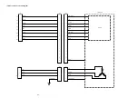
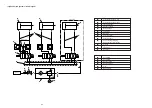
23. DRAWING OF THE TABLE
(1) LK-1910, 1920
230
110
360
42
398.5
390
75
10
85
R30
4 places on the rear side-
table stand installing hole
(Drill at the time of set-up)
Drawer stopper installing position
(One place on the rear side)
5-drilled hole 8
Drilled hole 16
25
R30
21
50
JUKI logotype
Manual pedal chain
inserting hole
6
Drilled hole 30, 51 spot face 16 deep
488
1040
184
170
182
38
71
54.5
62
8
Oil-drain funnel installing hole
(Drill at the time of set-up)
286
257
139.5
R10
R10
ø38
230
313.5
Pedal switch installing hole-2
places on the reverse side
(Drill at the time of set-up)
14.5
250.5
197.5
3-drilled hole 2,
10 deep
146.9
133.4
13.5
115
133.5
Power switch installing position-
2 places on the rear side
(Drill at the time of set-up)
R30
4-drilled hole 2,
10 deep
Drilled hole 28
23.4
53.6
280
77
373
35
14
10
R2
500
432
70
Right side
570
Drilled hole 17
R30
R2
(All corners)
R2
(All corners)
40
4-drilled hole 7, 14 spot face
7.5 deep
4-R10
8
180
200
93
20
438
527
700
199
964
810
1130
1200


