background image

– 23 –

    4. OPERATION AND ADJUSTMENT

WARNING:

Turn OFF the power before staring the work so as to prevent accidents caused by abrupt start of the 

sewing machine. 

6


Preset adjusting knob

4


Hand switch

!

2

!

1

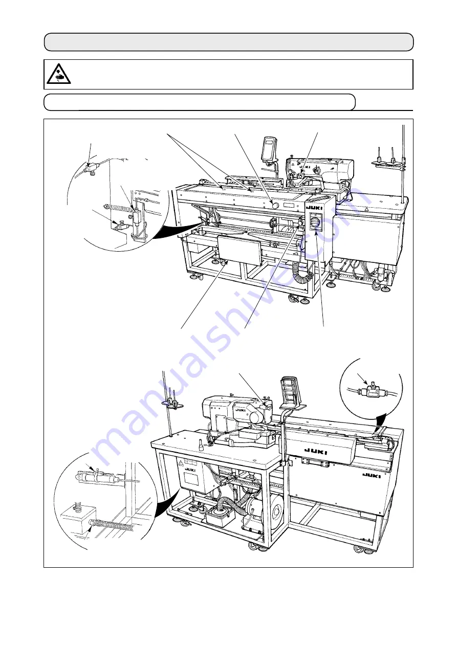
  4-1.  Operating switches and adjusting pneumatic components

7

8

9

Speed 

controller of 

the blower for 

the lifting the 

workpiece

!0

Speed controller 

of the blower for 

the carriage

Speedcontroller 

of the blower for 

the sucking the 

workpiece

Workpiece 

detector switch

1


Power switch

2


Pause switch

3


Knee switch

2


Machine head pause switch

Speed controller 

of the blower for 

the peeling off 

the workpiece

Sensor to detect the 

number of garment 

bodies stacked

Vacuum adjusting 

metal fittings

(1) Power switch


Use ths swtch to turn ON / OFF the power to the unt.

(2) Pause switch, Machine head pause switch


Use ths swtch to stop the machne from runnng.

Содержание AC-172N-1790

Страница 1: ...AC 172N 1790 INSTRUCTION MANUAL ENGLISH ...

Страница 2: ...ing the auxiliary clamp 15 2 Adjusting the auxiliary clamp 21 4 OPERATION AND ADJUSTMENT 23 4 1 Operating switches and adjusting pneumatic components 23 1 Power switch 23 2 Pause switch Machine head pause switch 23 3 Knee switch 24 4 Hand switch 24 5 Workpiece detector switch 24 6 Preset adjusting knob 24 7 Adjusting the air blower 25 8 Vacuum adjusting metal fittings 28 9 Sensor to detect the num...

Страница 3: ...the individual input 53 1 9 Copying the AC pattern 54 1 10 Changing over the garment type between men s and ladies garments 55 1 11 Changing over the pair stack 56 2 OPERATING AND OPERATION SETTING METHODS FOR DISCRETE SEWING MACHINE 57 2 1 Input of the presser type 57 1 Setting procedure of the presser type 57 2 Table of presser type 58 2 2 Performing pattern selection 58 1 Selection from the pat...

Страница 4: ...relation 88 1 2 Adjusting the needle thread trimmer 89 1 3 Adjusting the presser bar pressure 89 1 4 Adjustment of the bobbin presser unit 90 1 5 Thread tension 90 1 6 Replacing the clamp cushion 91 1 7 Adjusting the machine head 91 1 8 Replacing the fuse 92 2 GAUGE COMPONENTS 93 3 DAILY MAINTENANCE 94 3 1 Removing dust near the bobbin case 94 3 2 Cleaning the cooling filter 94 3 3 Cleaning the va...

Страница 5: ...erator to attend on four machines without causing one of them to stand idle or for the operator himself herself to become idle when two pieces of garment are set on 6 The clamping mechanism clamps the material securely without allowing any slippage during the sewing operation from inserting to stacking 7 Buttonholes can be sewn also to the front to center strips of ladies wear 8 The sewing speed c...

Страница 6: ...itch 7 Knee switch 1 2 Configuration of the main parts 8 Pause switch 9 Hand switch 0 Workpiece detector switch 1 Air gun 2 Preset adjusting knob supplied with the machine in the tool box 3 Tool box 4 Thread stand 5 Filter box 6 Machine head pause switch 9 2 4 5 1 0 2 3 1 6 7 5 3 8 4 6 ...

Страница 7: ... 2 Number of patterns that can be stored in memory 20 3 Power supply 200 to 240V 3 phase single phase Rated voltage 10 or less Without voltage changeover 4 Power source frequency 50 60 Hz 5 Power consumption 1000 VA supply voltage 10 or less 6 Operating air pressure 0 5 MPa 7 Air consumption 240 Nl min or less 8 Machine dimensions Width 1 910mm Depth 850mm Table Height 920 mm 9 Weight 300 kg 10 No...

Страница 8: ...mping plate which clamps the sewing machine head is installed under the front guard Be sure not to forget to remove the clamping plate 2 Remove screws 5 which are used to secure the front guard and the table Fit spanners 8 and 9 respectively on nuts 7 which are used to fix screw 5 Securing spanner 9 turn spanner 8 clockwise When one nut 7 is removed fix the remaining one with spanner 9 Fit hexagon...

Страница 9: ... bottle 6 is filled with water be sure to drain off the water by removing one touch joint 2 from regulator 4 and by pressing drain button 7 Drain off the water every time the ma chine is used either before or after op eration 1 Check to be sure that the power supply in use is 200 to 240 VAC 2 First confirm that power switch in OFF then connect the power cord to the power supply 3 Turn the power ON...

Страница 10: ...e sewing hook by loosening lock nut 2 and turning oil amount adjusting screw 3 Amount of supplied oil is reduced when turning the screws 3 clockwise Fix the screw with lock nut 2 after adjusting the lubrication for the sewing hook When you first operate your sewing machine after set up or after an extended period of disuse remove the bobbin case and apply a few drops of oil to the hook race In add...

Страница 11: ... the panel 1 Fix operation panel mounting plate 1 on base plate 2 Use setscrews 3 M5 x 25 supplied with the unit 2 Install operation panel 4 2 1 3 4 3 Tie cord 6 on the operation panel strut with cable clip band 5 5 6 ...

Страница 12: ...knuts 1 so that they securely hold the thread stand assembly 3 In the case of ceiling wiring pass the power cable through spool rest rod 2 3 6 Installing the thread stand 2 1 1 4 Connect cord 6 to connector 7 CN34 coming from the control box 5 Fix cord 6 at two points with clamps 8 located under the housing 6 7 6 8 8 ...

Страница 13: ...el cord 6 and grounding cord 8 at two locations underside the cabinet with clamps 9 4 Open the control box Connect connector 0 of the marking light to CN113 0 9 9 8 5 6 7 6 4 5 3 7 Installing the marking light 1 When installing the device temporarily fix mark ing light mounting base 1 on base plate 2 with setscrews 3 2 x M4 supplied with the unit 1 3 2 ...

Страница 14: ...king off lights 3 on preset table 1 When the device is cor rectly positioned securely tighten setscrews 3 2 x M4 2 1 1 2 3 3 3 8 Adjusting the marking light Setting procedure in the case the distance from the edge of placket material to the buttonhole is 15 mm 1 Loosen setscrews 1 2 Turn marking light 2 in the direction of the arrow to adjust the pointer to 15 of the seal adhered on the preset tab...

Страница 15: ...ction A of hand switch mounting plate 0 Mount both material edge detecting sensor asm 7 and mounting bracket 9 with air blower mounting bracket setscrew 8 Be sure to check that the setscrew does not come in contact with hand spinner set screw 1 3 Turn around bracket 9 so that the air hose faces the needle bar This setting is only available under the men s garment mode Be aware that the sewing mach...

Страница 16: ...r junction cord B asm 4 CN105 26 and blue cord contact to sensor junc tion cord B asm 4 CN105 27 respectively 7 Insert material edge detecting sensor asm cord 7 into material edge detecting sensor junction cord 3 8 Degrease the top surface at the location where reflective sheet 6 is to be affixed of feed plate 5 9 Affix reflective sheet 6 on feed plate 5 aligning with the end face of the slot of t...

Страница 17: ...e C at 65 mm under the AC mode 4 Press the ready key to bring the sewing ma chine into the sewing state Then place a piece of cloth of approximately A4 size on the preset section 5 Actuate the preset device to start sewing 6 Measure the distance D from the material edge to the edge of a buttonhole Enter the measured value in the field above the K26 pictograph Initial value is 65 mm 7 Now the posit...

Страница 18: ...t buttonhole is set at 50 mm and the material is placed at the location 75 mm away from the center of needle After the material is delivered from the preset table to the carriage the material edge is detected by the carriage The carriage moves to the left by 10 mm 75 65 To sew the first buttonhole The carriage moves to the left by 15 mm 65 50 In all the carriage has to move to the left by 25 mm Ho...

Страница 19: ...iary clamp 2 1 1 3 45 6 7 8 1 Remove five screws 1 to remove right cover 2 2 Remove three screws 4 and three nuts 5 from the underside to remove base plate 3 3 Write mark off lines with a pencil or the like on the joining surfaces of parts to easily understand the installing position at the time of re assembly then remove screws 6 and 7 There is a washer on the underside of rod end 8 Take care not...

Страница 20: ...ligned with the mark off lines 5 Supply air Securely tighten screws 6 and 7 with set ting plate support 2 pressed against preset table 1 6 Bundle two air hoses 3 and switch cable 4 with clamp 5 Tighten screw 6 Then slide the cover of duct 7 in the direction of the arrow Place two air hoses 3 and switch cable 4 in the duct and close the cover of duct 7 ...

Страница 21: ... 17 4 7 Slide the cover of duct 8 to place two air hoses 3 in the duct Then close the cover of duct 8 8 Replace switch cable 4 with the cable which is connected to CN219 8 3 ...

Страница 22: ... direction of the arrow At this time check to be sure that end block 2 and solenoid valve 4 are respectively provided with three bushings 3 on one side Tighten screw 9 while shifting end block 2 in the direction of the arrow 11 Tighten screw 0 and nut 1 Connect two air hoses 3 to solenoid valve 4 while matching their label numbers 1 and 2 those of the cor responding bushings Carefully check the mo...

Страница 23: ...nnectors 13 Install right cover 2 and secure with screws 1 14 Fit material presser rubber cushion 7 on clamp 6 Fit the cushion to the side which has a shorter distance from the bent section to the end face 15 Insert clamp 6 into clamp block 8 and secure with two setscrews 9 At this time adjust so that setscrews 9 are brought to the location of the slot in the top surface of clamp 6 ...

Страница 24: ... is posi tioned as shown in the figure 17 Loosen two screws 1 Adjust the height of preset table 0 so that it sinks by 1 mm when clamp 6 comes down to its lower position 18 If you want to change the lifting lowering speed of clamp 6 adjust speed controllers A and B To reduce the lowering speed of clamp 6 tighten speed controller B To reduce the lifting speed of clamp 6 tighten speed controller A ...

Страница 25: ...rt switch Press mode key 4 to display memory switch data level 1 edit screen A Press item select switches 0 to select item U51 Set the start switch selection to the hand switch with data change keys 1 to display edit screen B 3 Enabling the auxiliary clamp Keep mode key 4 held pressed on memory switch data level 1 edit screen B to display memory switch data level 2 edit screen C Press item select ...

Страница 26: ...oes up and the preset table moves to ward the machine head side If you press knee switch 9 while cloth suction lamp 3 stays on delivery of the material is stopped and the preset table returns to its initial position In the case the knee switch is set to be the start switch When you select item U51 to select knee switch D as the start switch the suction device keeps suck ing the material and the au...

Страница 27: ...e 0 Speed controller of the blower for the carriage Speedcontroller of the blower for the sucking the workpiece 5 Workpiece detector switch 1 Power switch 2 Pause switch 3 Knee switch 2 Machine head pause switch Speed controller of the blower for the peeling off the workpiece Sensor to detect the number of garment bodies stacked Vacuum adjusting metal fittings 1 Power switch Use this switch to tur...

Страница 28: ...h or the preset cancel switch Refer to the aforementioned Knee switch 1 5 Workpiece detector switch This switch prevents a malfunction when there is no workpiece set on the machine If either one of two detector switches 1 detects a workpiece the machine is actuated Take care not to place anything other than the sew ing products or hands on detector switches 1 If using a piece of light absorbing bl...

Страница 29: ...stacking the workpiece 2 The speed controllers used to adjust the air blow of air blow pipes 1 to 4 are those shown in the figure on the left 1 3 2 4 1 Speed controller of the blower for the carriage 2 Speed controller of the blower for the lifting the workpiece 3 Speed controller of the blower for the sucking the workpiece 4 Speed controller of the blower for the peeling off the work piece 3 Tabl...

Страница 30: ... increase the amount of air to be blown properly If sewing a light weight material or floppy material set speed controller 2 to the value adjusted of air to be blown 6 Adjusting the air blower for stacking the workpiece If sewing a heavy weight material or a large size material loosen speed controller 3 and 4 to increase the amount of air to be blown properly If sewing a light weight material set ...

Страница 31: ...r blow is adjusted with the speed controller When the manual switch of solenoid valve No 7 is pressed and turned the pusher is actuated and simultaneously the needle bar air blower is actuated Return the manual switch after the adjustment since the manual switch is locked with it pressed and turned Adjust the speed controller located on the black pipe branched from the yellow pipe connected from s...

Страница 32: ...es stacked 1 Sensor 2 mounted on cylinder 1 which driver pusher 4 detects the thickness of garment bod ies stacked on stacking board 3 when actuating the stacker 2 You can let the alarm occur at the time when the thickness of garment bodies stacked on the board reaches any desired value specified by change the position of sensor 2 with a Phillips type screwdriver Distance S has been factory adjust...

Страница 33: ...et board 1 back ward raise carriage 2 by hand and move preset board 1 toward you to return it to its home position Then connect the air to the ma chine To discharge air from the unit press one touch joint 3 in the direction of the arrow and remove hose 4 For the connecting procedure refer to 3 3 Connecting the air hose p 5 10 Measure to be taken in the case of power interruption during operation 1...

Страница 34: ... start the following work after turning the power off and ascertaining that the motor is at rest WARNING To protect against possible personal injury due to abrupt start of the machine be sure to start the following work after turning the power off and ascertaining that the motor is at rest Pass the needle thread in the order 1 to 2 as shown in the figures The threading can be done easily by using ...

Страница 35: ...kwise will increase bobbin thread tension and turning it counterclockwise will decrease the tension Adjust the bobbin thread tension to lower for synthetic filament thread and to higher for spun thread The thread tension is higher by approximately 0 05N when the bobbin case is set to the hook since idle prevention spring is provided When bobbin thread tension is adjusted make sure of the needle th...

Страница 36: ...heck to be sure that the bobbin case is properly installed in the correct po sition 2 There is a difference in the shape of bobbin case between the standard hook and the dry one They have noth ing in common with each other WARNING To protect against possible personal injury due to abrupt start of the machine be sure to start the following work after turning the power off and ascertaining that the ...

Страница 37: ...e has occurred during sewing perform replacing bobbin when carriage table 1 is in the state of B state that the sewing machine is cov ered with the table 2 Holding knob 2 open shuttle cover 3 3 Raise and hold latch lever 5 of bobbin case 4 to take it out The bobbin in the bobbin case will not come off provided that the latch lever is raised and held 4 To load the bobbin case in the shuttle put it ...

Страница 38: ... or counter clockwise will increase it 2 Read the required distance on scale 2 and marker 3 Then turn the knob until it reaches the specified value 3 Distance A can be adjusted with the range from 7 to 21 mm 4 When distance A cannot be set to the value indicated on the scale loosen the screws 5 which fix scale plate the plate has a screw on both sides and re adjust the position of the scale plate ...

Страница 39: ... clamping force When adjusting the position of the clamps or re placing the clamp cushion perform the adjustment below 1 Place workpiece 1 on the carriage as illustrated in the figure press and turn the manual switch on solenid valve 3 to actuate the clamp cylin der 2 Loosen locknut 4 and turn adjustment screw 5 in the direction of the arrow Then clamp cushion 6 will be raised 3 Adjust up or down ...

Страница 40: ...e 2 Once the presser plate pressure is fixed tighten the locknut and fix the adjusting screw They should come in close contact Provide an equal lateral clearance between the preset board and the cloth plate Provide a vertical clearance of 1 0 5 mm or less between the preset board and the cloth plate The longitudinal clearance between them should be 2 1 mm when the preset board is placed at the 21 ...

Страница 41: ... 2 Turn the power ON Press Ready key 7 to activate K55 8 adjuster adjustment mode Re fer to 1 4 Preparation of the device in the SET UP MANUAL for the adjuster adjustment mode 3 Press solenoid valve switch 8 9 to clamp the garment body with the sub clamps 4 While the sub clamps are clamping the garment body put a spring balance onto the garment body to measure the pressure applied by the sub clamp...

Страница 42: ... locknut 2 When sewing ladies wear loosen locknuts 2 in the stacking board on the left side as in the case of men s wear When sewing garment bodies without pockets lower locknuts 2 until they reach stacking board base 3 and tighten them to the extent where stacking board 1 is secured Flush WARNING Turn OFF the power before starting the work so as to prevent accidents caused by abrupt start of the ...

Страница 43: ...d B modes by changing over the memory switch data Refer to 2 15 Method of changing memory switch data p 77 2 The knee switch is used as start switch under the A mode and the hand switch is used under the B mode 3 Under both A and B modes the machine will start when releasing the start switch Be sure to avoid placing your hand s under the work clamp check and the needle with the start switch held p...

Страница 44: ... when the material is sucked the workpiece suction is stopped If you repeat steps 2 to 4 while the first material is being sewing the sewing machine is capable of performing continuous operation The mode has been factory set to A mode at the time of shipment The proper material setting 1 Men s shirts Place the material so that there is no clear ance between the side end of the material and presett...

Страница 45: ... 41 1 How to use the operation panel OPERATION 1 1 Configuration of the operation panel 1 9 0 2 3 4 5 6 6 5 3 2 3 4 4 8 9 0 1 7 8 7 8 9 0 1 2 5 6 5 2 3 4 1 7 ...

Страница 46: ...OOVE WIDTH LEFT key This key selects knife groove width left compensation display 3 COPY key Press this key when copying pattern 4 S e w i n g machine start key The sewing machine starts sewing of the selected LBH pattern 5 FORWARD key This key makes the feed mechanism travel forward stitch by stitch 6 BACK WARD key This key makes the feed mechanism travel backward stitch by stitch 7 PATTERN REG I...

Страница 47: ...READY key 2 Once the sewing is enabled the background color of the LCD turns green and the AC automatic sewing screen appears on the display 4 Starting sewing Place the sewing product on the sewing machine When you press the knee switch or the hand switch either switch which has been set as the start switch the sewing machine automatically starts sewing Refer to 2 15 Changing the memory switch dat...

Страница 48: ...witch data level 1 U54 pair stack is set to ON Refer to 1 11 Changing over the pair stack p 56 F Men s Ladies garment se lection Type of garment can be changed over between men s and ladies garments Refer to 1 10 Changing over between men s and ladies garments p 55 5 Work clamp check lower ing button The work clamp check is moved down to its lower position and the work clamp check lowering screen ...

Страница 49: ... but tonholes The number of buttonholes which has been registered to the currently selected AC pattern is displayed D Automatic sewing mode This button is displayed under the automatic sewing mode E Knife cancellation This button is displayed when the knife cancellation is effective The knife is not actuated while the knife cancellation button is displayed Button and display Description C B D E 2 ...

Страница 50: ...tch backward button The LBH pattern data set for the operation step to which the carriage is brought by means of button 3 or 4 is moved backward by one stitch 3 Material leftward feed but ton For a men s garment the carriage is moved forward to the next LBH pattern posi tion For a ladies garment the carriage is moved backward to the previous LBH pattern position 4 Material rightward feed button Fo...

Страница 51: ...Only when the AC data input screen blue A is displayed the AC pattern selection is enabled If the sewing screen green is displayed press READY key 2 to display the data input screen 2 Selecting the pattern number Press ITEM SELECT key 0 to display the target AC pattern number ...

Страница 52: ...s in operation under the AC mode the sewing machine stops sewing At this time the error screen appears to notify that the PAUSE switch has been pressed 3 A A B 1 Resetting the error When the error is reset by pressing RESET key 3 the manual sewing screen A appears on the display automatically ...

Страница 53: ...WARD FEED 3 the needle entry point of the sewing data is brought leftward by one needle entry point Return the work clamp check to the position to start re sewing 3 Starting sewing When you press the knee switch or the hand switch either switch which has been set as the start switch the sewing machine starts re sewing Refer to 2 15 Method of changing mem ory switch data p 77 for how to set the sta...

Страница 54: ... 4 Stop the sewing machine When the bobbin is wound with a predeter mined amount of thread bobbin winding lever 1 is released Press bobbin winding key 6 or press the knee switch or the hand switch to stop the sewing machine Then remove the bobbin and cut bobbin thread with thread trimmer retaining plate 3 Press WINDER key 6 and the sewing machine stops and returns to the normal mode When you press...

Страница 55: ...ted up When the existing value is equal to the set value count up screen is displayed No of pcs DOWN counter Every time one cycle or one continuous stitching is performed the existing value is counted down When the existing value is reached to 0 count up screen is displayed Counter not used E 2 A 1 B 0 1 C D 9 5 Count up releasing procedure When count up condition is reached during sewing work the...

Страница 56: ...C pattern to the AC pattern number which has already been reg istered Twenty different patterns 1 to 20 can be used as AC patterns 4 Selecting the equal interval input Press the ITEM SELECT key 0 to blink the equal interval individual input selection B Select the equal interval input using DATA CHANGE key 1 Press DATA key 8 to confirm the AC pattern number to be newly registered Then the equal int...

Страница 57: ...number which has already been reg istered Twenty different patterns 1 to 20 can be used as AC patterns 4 Selecting the individual input Press the ITEM SELECT key 0 to blink the equal interval individual input selection B Select individual input using DATA CHANGE key 1 and press DATA key 8 Then the AC pattern number to be newly registered is confirmed and individual input screen C is displayed 5 Se...

Страница 58: ...ber for copying Select the source pattern number for copying on the pattern selection screen Refer to 2 2 Performing pattern selec tion p 46 3 Calling the copy screen Press COPY key 3 to display the copy screen A 4 Selecting the destination pattern number for copying Pattern No B which is not used flashes on and off Press DATA CHANGE key 1 to select the destination pattern number for copy ing To e...

Страница 59: ... to place the material on the sewing machine For men s garments the position at which the sewing product is preset is the sewing starting position of the first sewing pattern For ladies garments the position that is reached by moving the material toward the right by 610 mm from the position at which it has been preset is the sewing starting position of the first sewing pattern For both men s and l...

Страница 60: ... 1 Displaying the AC data input screen Display the AC data input screen blue for the AC pattern number to be sewn 2 Changing over the pair stack Press DATA key 8 to display the data chang ing screen B The changeover of the pair stacker can be done af ter having entered the last data on the LBH sewing pattern number Press ITEM SELECT key 0 Then press ITEM SELECT key 0 twice while the last data C on...

Страница 61: ... key 2 to change over to the input mode 2 Select the presser type Press MODE key 4 to display Memory switch data level 1 edit screen A Press ITEM SELECT key 0 to call Type of presser foot Then press DATA CHANGE key 1 The pictograph is displayed as shown in the figure below Select the type of the work clamp check installed on the sewing machine referring to 2 Table of presser type p 58 Type 1 Type ...

Страница 62: ...you desire with the register switch When the pattern is registered once pattern selection can be performed by pressing only the switch Refer to 2 11 Using pattern register key p 72 2 A 1 7 B Type Part No of presser foot Type 1 B151177 1 000 Type 2 B151177 2 000 Type 3 B151177 3 000 Type 5 Set type 5 when using the presser other than type 1 to 3 Change Presser size width and Presser size length of ...

Страница 63: ...at bar tacking section Press DATA CHANGE key 1 and set value D goes up or comes down and the thread tension can be changed The relation between the finish of sewing and the set value is as shown in table below Set the value referring to the table 1 3 4 A C B D Set value on panel Initial value Purl stitch 1 Tension at paral lel section Crest is low ered 120 Crest is raised 2 Bar tacking ten sion Th...

Страница 64: ...t sewing again When you press the knee switch or hand switch which is preset as the start switch the sewing machine re starts sewing To perform re sewing from the start Sewing motion stop status Error display screen B is displayed 1 Release the error Press RESET key 3 to release the error Then step motion screen C is displayed 2 Return the presser to the sewing product setting position Press again...

Страница 65: ...ape Press SHAPE key 2 and shape selec tion screen C is displayed Shape D which is selected at present flashes on and off on the display Select shape D to sew with DATA CHANGE key 1 It is possible to select the shape from among 12 shapes at the time of your purchase However it is possible to select the shape from among maximum 30 shapes by increasing the shape selection level K04 Refer to 2 15 Meth...

Страница 66: ...r type 20 Square round type 21 Square straight bar tacking type 22 Square taper bar tacking type 23 Radial semilunar type 24 Radial round type 25 Semilunar radial type 26 Semilunar round type 27 Bar tacking 28 Bar tacking right cut 29 Bar tacking left cut 30 Bar tacking center cut PANEL DISPLAY PANEL DISPLAY PANEL DISPLAY PANEL DISPLAY PANEL DISPLAY PANEL DISPLAY PANEL DISPLAY PANEL DISPLAY PANEL ...

Страница 67: ...ch changes numerical value Increase or decrease the set value with DATA CHANGE key 1 to change the value No such as is attached to the data item which selects pictograph Pictograph can be selected with DATA CHANGE key 1 For the details of sewing data refer to 2 9 Sewing data table p 65 8 0 1 1 Set the mode to the input mode When the back light of LCD display 1 shows the input mode in blue color it...

Страница 68: ... mode When the back light of LCD display 1 shows the input mode in blue color it is possible to set When the back light shows the sewing mode in green color press READY key 2 to change over to the input mode 2 Call sewing data with without edit change over screen Press DATA key 8 for as long as three seconds and data with without edit changeover screen A or B is displayed 3 Select sewing data you ...

Страница 69: ...t is cut by cloth cutting knife However in case of bar tack shape Nos 27 28 29 and 30 of S01 sewing length is set By making effective U19 Function of plural mo tions of cloth cutting knife of memory switch data make the plural motions of knife by the knife size set in the item U18 Cloth cutting knife size and the sewing product is cut Refer to 2 16 Memory switch data list p 78 3 0 to 120 0 0 1mm S...

Страница 70: ...This item sets number of stitches in the upper 90 of eyelet shape 1 to 8 1 1 S16 Eyelet width This item sets crossuise size of the inside of eyelet shape Actual needle entry point is the dimension to which S04 Knife groove width left is added 1 0 to 10 0 0 1mm 1 S17 Eyelet length This item sets lengthwise size of the inside of eyelet shape 1 0 to 10 0 0 1mm 1 S18 Round type shape length This item ...

Страница 71: ...rforming basting 1 0 to 5 0 0 1mm 3 S36 Rolling length of basting This item sets rolling length of needle thread when performing basting 2 0 to 20 0 0 1mm 3 S37 Rolling pitch of basting This item sets rolling pitch of needle thread when performing basting 0 2 to 5 0 0 1mm 3 S38 Rolling width of basting This item sets rolling width of needle thread when performing basting 0 0 to 4 0 0 1mm 3 S39 Len...

Страница 72: ...2 S53 Left parallel section tension 1st cycle of double stitching This item sets needle thread tension at left parallel section of 1st cycle at the time of double stitching 0 to 200 1 2 3 S54 Right parallel section tension 1st cycle of double stitching This item sets needle thread tension at right paral lel section of 1st cycle at the time of double stitch ing 0 to 200 1 2 3 S55 Tension at 1st bar...

Страница 73: ...wing 0 0 to 5 0 0 1mm 2 S66 Crosswise compensation of tie stitching at the start of sewing This item sets start position of tie stitching in cross wise direction at the start of sewing 0 0 to 2 0 0 1mm 2 S67 Tie stitching width at the end of sewing This item sets tie stitching width at the end of sew ing 0 1 to 1 5 0 1mm S68 Number of stitches of tie stitching at the end of sewing This item sets n...

Страница 74: ...h of going This item sets sewing pitch of going side of bar tack ing shape Shape Nos 27 28 29 and 30 of S01 0 200 to 2 500 0 025mm S87 Width of going This item sets width of going side of bar tacking shape Shape Nos 27 28 29 and 30 of S01 0 1 to 3 0 0 05mm S88 Pitch of coming This item sets sewing pitch of coming side of bar tacking shape Shape Nos 27 28 29 and 30 of S01 0 200 to 2 500 0 025mm S89...

Страница 75: ...58 When creating pattern data quite newly it is convenient to copy the initial value pattern Refer to 2 5 Using initial value pat tern p 61 3 Call copy screen Press COPY key 3 and copy screen A is displayed 4 Select pattern No of copy destination Pattern No B which is not used flashes on and off in the display Press DATA CHANGE key 1 and select the No you desire to copy When you desire to erase th...

Страница 76: ...input mode 2 Call pattern register screen Press key P1 and P2 to 7 which you desire to register pattern No for as long as 3 seconds and pattern register screen A is displayed 3 Select pattern No Pattern No B which can be used at present flashes on and off in the display Press ITEM SELECTION key 0 and select the pattern No you desire to register When trash can is selected register can be released 4...

Страница 77: ...ssible to register parameters When the back light shows the sewing mode in green color press READY key 2 to change over to the input mode 2 Call parameter register screen Press key F1 and F2 to 8 which you desire to register the parameter for as long as 3 seconds and parameter register screen A is displayed 3 Select parameter Item B which can be registered with the key flashes on and off Press ITE...

Страница 78: ...ll pattern selection screen Press PATTERN NO key 7 and pattern selection screen A is displayed Pattern No B which is selected at present flashes on and off A 1 7 B 2 0 1 Selection of continuous stitching data 3 Select continuous stitching Press ITEM SELECTION key 0 and patterns which have been registered are changed over and displayed in order Cycle data No and continuous stitching data No which h...

Страница 79: ...pears Pattern No D which is sewn first flashes on and off In this state it is possible to edit the data 4 Select editing point Press ITEM SELECTION key 0 and editing point moves in order of pattern No jump feed mount pattern No jump feed amount and flashes on and off When moving the editing point up to the last data additional indication pictograph is displayed 5 Change data of selected editing po...

Страница 80: ...hen set size C of knife attached with DATA CHANGE key 1 For the details refer to 2 16 Memory switch data list p 78 3 Set the function of the plural motions of cloth cutting knife to effective Next press again ITEM SELECTION key 0 to call Function of the plural motions of cloth cutting knife D Then set the plural motions of cloth cutting knife to the effective status with DATA CHANGE key 1 For the ...

Страница 81: ...nd memory switch data level 2 edit screen B is displayed 3 Select memory switch data to change Press ITEM SELECTION key 0 and select the data item which you desire to change 4 Change data There are one data item to change the numeri cal value and the other data item to select the pictograph in the memory switch data No C such as is attached to the data item to change the numerical value Set value ...

Страница 82: ... stitch 400 to 4200 100sti min 3000sti min U13 Soft start speed setting 5th stitch 400 to 4200 100sti min 4000sti min U14 Kind of presser Set the kind of the presser 2 1 Input of the presser type p 57 Type 1 U15 Presser size width When type 5 of U14 Kind of presser is set input the width of the presser 3 0 to 10 0 0 1mm 3 0mm U16 Presser size length When type 5 of U14 Kind of presser is set input ...

Страница 83: ...trimmer release motion is inputted 0 to 15 0 0 1mm 1 0mm U24 Bobbin thread trimming motion start dis tance Distance from the start of sewing to the start of bobbin thread trimmer release motion is inputted 0 to 15 0 0 1mm 1 5mm U25 Counter updating unit Unit to update sewing counter is set 1 to 30 1 1 U26 Total number of stitches Non display Display Non display Display Non display U51 Start switch...

Страница 84: ...hine can be limited When K06 Selection of machine type is set to dry head type max speed is automatically lim ited to 3 300 sti min 400 to 4200 100sti min 3600sti min K08 Compensation of unsteady needle thread tension Output value of needle thread tension is wholly offset and compensated 30 to 30 1 0 K09 Output time of needle thread tension changed value When data related to needle thread tension ...

Страница 85: ...is dis abled Material edge sensor is dis abled Material edge sensor is en abled K24 Marking light setting Laser marker is disabled Marking light is disabled Marking light is enabled K25 Auxiliary clamp setting Auxiliary clamp is disabled Auxiliary clamp is disabled Auxiliary clamp is enabled K26 Material edge detecting sensor positioning 30 0 to 100 0 0 1 0 1mm 65 0 Adjust the distance between the...

Страница 86: ...ackward sensor 3 Head tilt sensor 4 Preset intermediate sensor 4 Stop switch Head side switch 5 Carriage tilt sensor 5 Needle rocking sensor 6 Cloth sweeping sensor 6 Sewing machine woodruff plate sensor 7 No of pcs of stacking sensor 7 Knee switch sensor 8 Stop switch AC main body side switch 8 Hand switch sensor 9 Sub clamp lowering cylinder sensor 9 Cloth detection sensor 0 Sub clamp lifting cy...

Страница 87: ... Possible to re start after reset Data input screen E025 Detection of step out of needle thread trimmer motor When step out of motor is detected at the time when needle thread trimmer motor passes origin sensor or starts operation Possible to re start after reset Data input screen E026 Detection of step out of bobbin thread trimmer motor When step out of motor is detected at the time when bobbin t...

Страница 88: ...after pressing can cel button Pattern list screen E402 Pattern deletion error When trying to perform deletion in case the remaining pattern No which has been registered is only one Possible to re start after pressing can cel button Pattern list screen E410 When sewing counter set value is smaller than the number of times of sewing of the sewing pattern which is selected at present Possible to re s...

Страница 89: ...Possible to re start after reset Sewing data input screen E497 Presser size error Length direction front When stitching data exceeds the size of front of length direction of presser Possible to re start after reset Sewing data input screen E498 Presser size error Width direction right and left When stitching data exceeds the size of both right and left of width direction of presser Possible to re ...

Страница 90: ...power of servo control p c b fluctuates 15 or more Turn OFF the power E905 Abnormality of temperature of heat sink for servo control p c b When temperature of heat sink of servo control p c b is 85 C or more Turn OFF the power E907 Zigzag width motor origin retrieval error When origin sensor signal is not inputted at the time of origin retrieval motion Turn OFF the power E908 Y feed motor origin r...

Страница 91: ...nsor even when three seconds or more have passed from com mand to move carriage to preset side Turn OFF the power E985 Preset is not advanced Preset is not advanced even when a specified period of time has passed from the preset advance command The sub clamp lowering cylinder sensor fails to operate The sub clamp lifting cylinder sensor fails to operate Turn OFF the power E986 Preset is not return...

Страница 92: ...p between the bottom end of the needle bar and the throat plate where the bottom end of the needle bar touches the top of the part 2 B of the timing gauge 3 Loosen setscrew C of the hook sleeve and align blade point of the sewing hook with the center of needle hole Make adjustment so that a clear ance of approx 0 05 mm is provided between the needle and the blade point of the hook 3 Adjusting the ...

Страница 93: ...g blade of upper knife 4 over the length with no clearance and so that the needle thread trimmer securely holds the thread regardless of the position of the thread trimming blade at which the thread is trimmed 1 2 Adjusting the needle thread trimmer Adjusting the height of the needle thread trimmer To adjust the height of the needle thread trimmer loosen setscrew 1 Set the height of trimmer as low...

Страница 94: ...iver into the slot of thread tension post 3 and turn it 3 To change the pressure of the thread take up spring insert a thin screwdriver into the slot of thread tension post 3 while screw 2 is tight ened and turn it Turning it clockwise will in crease the pressure of the thread take up spring Turning it counterclockwise will decrease the pressure Adjusting the thread take up amount of the thread ta...

Страница 95: ...he clamp cushion 1 2 3 0 5 to 2 0 Spacer 1 7 Adjusting the machine head Spacer Feed plate The lowest part of the feed block Clamp table Sewing machine bed If the machine head comes down from its normal position due to aged deterioration the folded edge of the material and the seam the edge may not be properly aligned when placing the material position on the machine head If the space provided betw...

Страница 96: ... shock hazards turn OFF the power and open the control box cover after about five minutes have passed 2 Open the control box cover after turning OFF the power without fail Then replace with a new fuse with the specified capacity 3 Open the cover If any of the LEDs on the PCB is on wait until the lighted LED goes out and re place the fuse with a new one If you replace the fuse when any of the LEDs ...

Страница 97: ...81000A B1552782000 B1552783000 D1508771K00A D1508772K00 D1508773K00 Sewing area A B C A B A B Cloth cutting knife A Knife size inch B Knife size mm C Mark D Part No 1 4 6 4 F B2702047F00 3 8 9 5 K B2702047K00A 7 16 11 1 I B2702047I00 1 2 12 7 L B2702047L00A 9 16 14 3 V B2702047V00 5 8 15 9 M B2702047M00A 11 16 17 5 A B2702047A00 3 4 19 1 N B2702047N00 7 8 22 2 P B2702047P00 1 25 4 Q B2702047Q00A 1...

Страница 98: ...emove it 2 Wash the filter 2 under running water 3 Reinstall the filter 2 and the screen kit 1 Hole under table for fan Table Hold knob 2 and open hook cover 1 Then re move dust thread waste and cloth waste near bobbin case 3 If dust collects near the bobbin case sewing is deteriorated WARNING To protect against possible personal injury due to abrupt start of the machine be sure to start the follo...

Страница 99: ... switch by means of the air gun to remove dust 3 5 Cleaning the carriage and lubricating to the drive section 3 4 Draining of the air regulator When bottle 1 is filled with water draw out one touch joint 3 from regulator 2 and press drain button 4 to perform draining It is recommended to perform draining each time before operating the machine or after operating 2 1 4 3 1 2 3 Feed plate Sewing mach...

Страница 100: ...resase bobbin thread tension Purl stitching 0 05 to 0 1N Increase pre tension p 59 p 31 4 Wobbling at the start of sewing 1 Thread tension at parallel section is too low 2 Position of needle thread trimmer is too high 3 Stroke of thread take up spring is too large Increase the thread tension at paral lel section Lower the needle thread trimmer to such an extent that it does not come in contact wit...

Страница 101: ...ntact with needle when it opens 4 Needle does not come to the center of the needle hole of throat plate 5 Needle stop position is low and the needle comes in contact with the needle thread trimmer when it closes Replace the needle Adjust the needle to hook timing Adjust the installing position of nee dle thread trimmer Re adjust the installing position of throat plate base p 30 p 88 p 89 13 Knife ...

Страница 102: ...0 0 0 0 0 0 0 0 0 0 0 0 0 0 0 S44 Speed setting of basting sti min 2000 2000 2000 2000 2000 2000 2000 2000 2000 2000 2000 2000 2000 2000 2000 2000 2000 2000 2000 2000 2000 2000 2000 2000 2000 2000 2000 2000 2000 S45 Sewing together function without with Without Without Without Without Without Without Without Without Without Without Without Without Without Without Without Without Without Without Wi...

Отзывы: