


6.2 MAINTENANCE ON EACH UNIT
y
yy
yyy
6-3
6
CAUTION
Do not put watches, clocks, or magnetic cards
close to the modulator unit since this unit holds
magnetrons having strong magnetic force.
Failure or data destruction of the above devices
may result.
After finishing the maintenance work, turn “ON” the safety switch of scanner unit.
Precautions in Mounting the Cover
When the cover is removed for regular checkup and replacement of parts and refitted after such work, the
procedures of fastening bolts shall be taken with the following precautions:
(a) The proper fastening torque of the fitting bolts (M8) is 1176 to 1470 N•cm (120 to 150kgf•cm) (which
makes the inside water-tight and protects the packing against permanent compressive strain).
The packing starts being produced from a torque of approximately 1470N•cm (150kgf•cm) on the cover.
Do not fasten the bolts with a torque exceeding the specified value. Otherwise, the screws may be
broken.
(b) Use an offset wrench of 11 mm
u
13 mm or a double-ended wrench of 13 mm
u
17 mm (not longer than
200 mm).
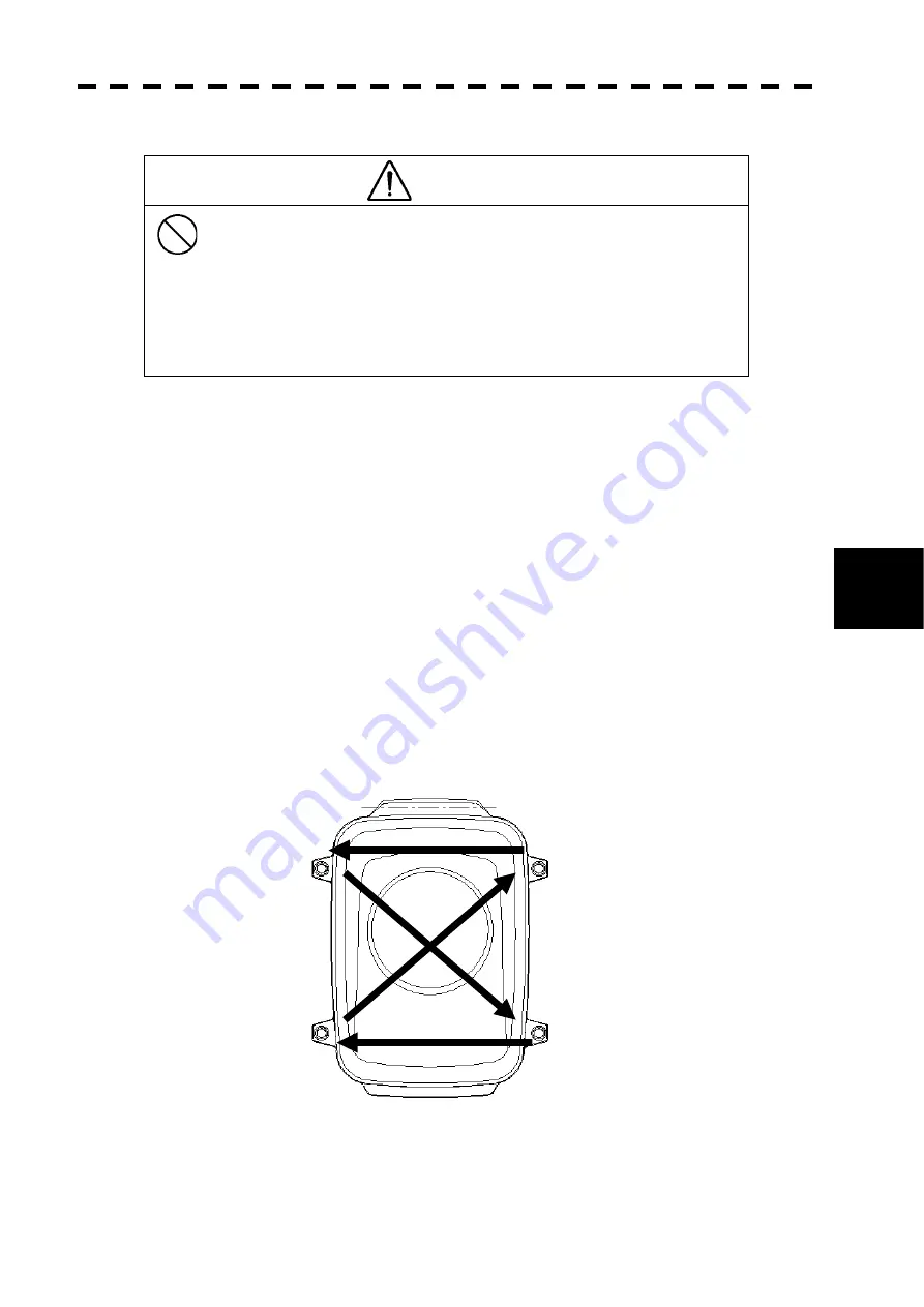
(c) Screw all the bolts by hand first to prevent them playing, then fasten them evenly in order not to cause
one-sided fastening. (Fasten the bolts with 25% of the required torque at the first step.)
*: Fasten the bolts in the diagonal order.
Top View of NKE-316
Figure 6.1 Bolt Tightening Procedure of NKE-316 Cover
ԛ
Ԛ
ԙ
Ԙ
Содержание JMA-610 Series
Страница 2: ......
Страница 20: ...xviii...
Страница 22: ...xx...
Страница 24: ......
Страница 29: ...1 5 1 1 4 EXTERIOR DRAWINGS y Fig 1 1 Exterior Drawing of Scanner Unit Type NKE 316 Unit mm...
Страница 30: ...1 6 Fig 1 2 Exterior Drawing of Processing Unit Type NDC 1486 Unit mm...
Страница 31: ...1 7 1 1 4 EXTERIOR DRAWINGS y Fig 1 3 Exterior Drawing of Operating Unit Type NCE 7882A Unit mm...
Страница 38: ...2 5...
Страница 40: ...2 7...
Страница 41: ...2 8 2 2 2 MENU LIST yy...
Страница 42: ...2 9...
Страница 43: ...2 10 2 2 2 MENU LIST yy...
Страница 48: ......
Страница 104: ...3 56...
Страница 106: ......
Страница 110: ...4 4 Figure 4 3...
Страница 112: ......
Страница 122: ...5 10...
Страница 124: ......
Страница 130: ...6 6...
Страница 131: ...SECTION 7 TROUBLE SHOOTING 7 1 FAULT FINDING 7 3 7 2 TROUBLE SHOOTING 7 5 7 3 REPLACEMENT OF MAJOR PARTS 7 7...
Страница 132: ......
Страница 142: ...7 10...
Страница 143: ...SECTION 8 AFTER SALES SERVICE When you Request for Repair Recommended Maintenance Radar Failure Check List...
Страница 144: ......
Страница 147: ...SECTION 9 DISPOSAL 9 1 DISPOSAL OF THE UNIT 9 1 9 2 DISPOSAL OF USED BATTERIES 9 2 9 3 DISPOSAL OF USED MAGNETRON 9 3...
Страница 148: ......
Страница 152: ...9 4...
Страница 154: ......
Страница 160: ...10 6...
Страница 162: ......
Страница 165: ...APPENDIX Fig 1 Block Diagram of JMA 610...
Страница 168: ...Fig 4 Internal Connection Diagram of Scanner Unit NKE 316...
Страница 169: ...APPENDIX Fig 5 Internal Connection Diagram of Control Unit NCM 883...
Страница 171: ......