background image

06.14

F561

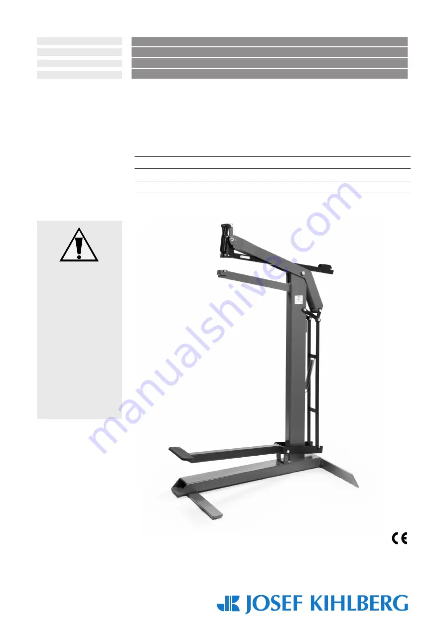
Manual bottom stapler
Manuell bottenhäftare
Manuelle Bodenheftmaschine
Agrafeuse manuelle pour fonds et côtés de cartons

From series no 1304461

Från serienummer 1304461    

Ab Serie-Nr. 1304461 

A partir du no de série 1304461

ENGLISH 3
SVENSKA 14
DEUTSCH 26
FRANÇAIS 38

Before using the 

bottom stapler, read the 

operating instructions 

carefully.

Läs igenom bruks-

anvisningen noga innan 

du använder maskinen.

Vor dem Gebrauch der 

Bodenheftmaschine 

die Betriebsanleitung 

aufmerksam lesen.

Avant l’utilisation de 

l’appareil, consultez 

soigneusement le 

mode d’emploi.

 OPERATING INSTRUCTIONS


Translation of original manual

 BRUKSANVISNING 

Original bruksanvisning

 BETRIEBSANLEITUNG 

Übersetzung der Originalbetriebsanleitung

 MODE D‘EMPLOI 

Traduction du mode d’emploi original

Содержание F561

Страница 1: ...using the bottom stapler read the operating instructions carefully Läs igenom bruks anvisningen noga innan du använder maskinen Vor dem Gebrauch der Bodenheftmaschine die Betriebsanleitung aufmerksam lesen Avant l utilisation de l appareil consultez soigneusement le mode d emploi OPERATING INSTRUCTIONS Translation of original manual BRUKSANVISNING Original bruksanvisning BETRIEBSANLEITUNG Übersetz...

Страница 2: ...r 10 7 3 Removing jammed staples 10 7 4 Adjustment stapling head bearing 11 7 5 Adjustment staple clinch 11 7 6 Replace stapling head 12 7 7 Replace feed spring or pusher 12 7 8 Replace driver blade or return springs 12 8 Trouble shooting 12 9 Spare parts kit 50 9 Parts list with recommended wear parts 51 Exploded drawing 52 10 Parts list Head HH561 12 22 53 Exploded drawing 54 SE JOSEF KIHLBERG A...

Страница 3: ...pages and increase the reliability and service life of the bottom stapler The operating instructions must always be available at the place of operation of the bottom stapler They must be read and observed by all persons concerned with work on the bottom stapler This work specifically includes operation refilling of operating material fault elimination and maintenance In addition to the operating i...

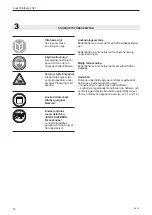
Страница 4: ...e condition of the bottom stapler at regular intervals for defects or worn parts Never use a bottom stapler that has defective or worn parts for sevice work refer also to chapters 7 1 and 7 2 3 SAFETY INSTRUCTIONS Inform yourself Read the operating instructions carefully Protect yourself When operating the bottom stapler wear eye and or ear protection Warning Danger of crushing Do not put your fin...

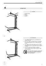
Страница 5: ...ositioned carton 3 The stapling head automatically pushes a staple through the carton and the staple clinches against the anvil 4 When you release the treadle the stapling head is returned and the bottom stapler is ready for next stapling 4 1 DESIGN 1 Stapling head 2 Anvil 3 Treadle 4 Pusher Fig 1 Fig 2 Warning before stapling ensure that no part of your body is underneath the stapling head 3 2 1 ...

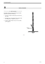
Страница 6: ...er is delivered with the rear foot dis assambled Assemble as following 1 Remove the bottom stapler and the rear foot from the carton 2 Assemble the rear foot Fig 3 1 and support 3 2 according to Fig 3 Tighten the screws 3 Place the bottom stapler on level firm and clean working ground 1 2 ...

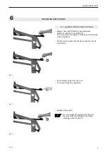
Страница 7: ... JK561 18 or JK561 22 The correct type of staple is marked on the left side of the magazine Pull the pusher back and lift up the pusher into its rear holder Insert staple strips from the rear Do not overload the magazine Release the pusher Do not release the pusher directly from the rear when the magazine is empty carefully guide it forward Fig 4 ...

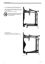
Страница 8: ... 1 Ensure to use the right length of the staple refer to chapter 6 3 Place the carton on the anvil holder Press the treadle The stapling head presses the carton and automatically clinches the staple against the anvil Fig 7 Fig 8 Warning before stapling ensure that no part of your body is underneath the stapling head ...

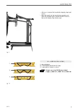
Страница 9: ... length of staple too short Always use Josef Kihlberg original staples JK561 15 JK561 18 or JK561 22 Fig 9 When you release the treadle the stapling head will return Move the carton to the next staple position and press the treadle again Repeat until the correct amount of staples have been used Fig 10 3 2 1 ...

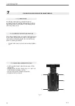
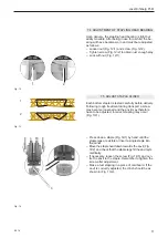
Страница 10: ...THE BOTTOM STAPLER This bottom stapler does not require special servicing It only needs regular cleaning with a non aggressive non corrosive cleaning agent Do not remove any parts for cleaning purposes Check if all screws and nuts are securely tighten ed Pull the pusher back to take the pressure off the staple strip Slightly loosen the five screws Fig 11 1 and 11 2 that hold the front plate one tu...

Страница 11: ... hit the anvil sym metrically If necessary loosen the screw Fig 14 3 and cen tre the anvil to the staple Remember to tighten the screw after adjustment Make a test stapling in a piece of cardboard If the anvil is correctly adjusted the clinch should be as shown in Fig 13 2 7 4 ADJUSTMENT OF STAPLING HEAD BEARING Upon delivery the stapling head bearing is tight but easily movable After being in use...

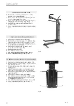
Страница 12: ...sassemble the two cylinder screws holding the stapling head to its bearing Fig 15 2 4 Replace the stapling head and assemble in reverse order 5 Adjust the stapling head to the anvil as described 7 5 Fig 15 7 8 REPLACE DRIVER BLADE RETURN SPRINGS 1 Remove the stapling head as per chapter 7 6 2 Dismantle the four screws Fig 16 1 and remove the unit from the rail 3 Dismantle the screw Fig 16 2 and re...

Страница 13: ...ples Check if the feeder spring is not defective If necessary replace Check if the staple pusher is not defective If necessary replace Clean the staple track Check return spring in the stapling head If necessary replace Check if stapling head bearing has no play refer to chapter 7 4 Check if anvil is properly centered refer to chap ter 7 5 Check if driver is not damaged If necessary replace Check ...

Страница 14: ...nde underhåll 22 7 1 Smörjning 22 7 2 Rengöring av bottenhäftaren 22 7 3 Avlägsna en klammer som fastnat 23 7 4 Inställning av häfthuvudets lagring 23 7 5 Inställning av städ 7 6 Byte av häfthuvud 24 7 7 Byte av frammatarfjäder eller frammatare 24 7 8 Byte av drivare eller returfjäder 24 8 Felsökning 25 9 Reservdelssatser 50 10 Reservdelslista 51 Sprängskiss 52 11 Reservdelslista häfthuvud 53 Sprä...

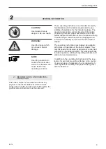
Страница 15: ...rstås av all personal som använder häftaren Som tillägg till maualen skall bestämmelse för före byggande olycksfallsrisker följas för det land där produkten används Det skall också iakttagas tekniska förordningar angående säker och riktig användning FÖRBUD Symbolen används vid fara för liv och lem VARNING Symbolen används vid risk för materiella skador OBSERVERA Symbolen används för allmänna instr...

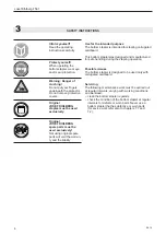
Страница 16: ...ndet konditionen på häftaren och se till att inga defekta eller utslitna delar förekommer för mer information angående service se 7 1 and 7 2 3 SÄKERHETSFÖRESKRIFTER Informera dig Läs igenom bruks anvisningen noga Skyddsutrustning Bär skyddsutrustning för ögon och öron när du använder bottenhäftaren Varning Akta fingrarna Stoppa inte fingrar eller andra kroppsdelar under skyddet Plocka inte bort s...

Страница 17: ...När du aktiverar fotpedalen förs automatiskt en klammer ut ur häfthuvudet genom kartongen och böjs mot städet 4 När du avaktiverar fotpedalen returnerar häfthu vudet automatiskt och häftaren är klar för nästa klammer 4 1 SAMMANSÄTTNING 1 Häfthuvud 2 Häftstäd 3 Fotpedal 4 Frammatare Varning innan du häftar säkerställ att ingen del av din kropp är under häfthuvudet Fig 1 Fig 2 Fig 1 3 2 1 4 1 2 ...

Страница 18: ... foten och främre sidostöd demonterad Monteras enligt följande Tag ur bottenhäftaren ur kartongen Bakre foten är bipackad inuti stativet skyddad med wellpapp Montera bakre foten Fig 3 1 och sidostöd 3 2 till stativet och drag fast skruvarna Placera bottenhäftaren på ett rent plant underlag Fig 3 1 2 ...

Страница 19: ...en etikett som visar aktuell klammertyp Dra frammataren bakåt och lyft upp den i sin bakre hållare Klammerstavarna förs in bakifrån Ladda inte så många klammer i magasinet att frammataren skadas när slutstycket fälls ner igen Frigör frammataren Släpp aldrig frammataren från sitt bakersta läge vid tomt magasin utan för fram det försiktigt för hand 6 ANVÄNDNING Fig 5 Fig 6 Fig 4 ...

Страница 20: ...tel 6 1 Kontrollera att du laddat med rätt benlängd av klammern se kapitel 6 3 Placera kartongen på städhållaren Tryck ned fotpedalen Häfthuvudet pressas mot kartongen och bockar klammern automatiskt mot häftstädet Varning Innan du påbörjar häftning kontrollera att ingen kroppsdel finns under skyddet Fig 7 Fig 8 ...

Страница 21: ...ammern 3 För kort benlängd av klammern Använd alltid Josef Kihlberg original klammer JK561 15 JK561 18 eller JK561 22 När du släpper upp fotpedalen så återvänder häft huvudet till sitt ursprungsläge Flytta kartongen till nästa klamringsläge och aktivera fotventilen igen Upprepa detta tills rätt antal klamringar har uppnåtts Fig 9 ...

Страница 22: ...ÄFTAREN Denna bottenhäftare behöver inget speciellt underhåll Den behöver regelbunden rengöring med ett neutralt rengöringsmedel ej frätande Demontera inte några delar vid rengöring Kontrollera dagligen att alla skruvar och muttrar är åtdragna Lossa de fem skruvarna Fig 11 1 och 11 2 som håller den främre kulissen ett varv Ta bort den fastnade klammern nedåt Dra åt de fem skruvarna igen 7 3 AVLÄGS...

Страница 23: ...a symme triskt Om städet behöver justeras lossa skruven Fig 14 3 och centrera städet så att klammer träffar skålarna symmetriskt Drag åt låsskruven efter justeringen Gör en test genom att klamra i en kartong En klam ring med korrekt justerat städ visas i Fig 13 2 7 4 INSTÄLLNING AV HÄFTHUVUDETS LAGRING När häftaren har använts en längre tid kan ett glapp uppstå i häfthuvudets lagring så att en jus...

Страница 24: ...uvudet och montera i omvänd ordning 5 Justera häfthuvudet så att klammern bockas sym metriskt se 7 5 Fig 12 7 8 BYTE AV DRIVARE RETURFJÄDRAR 1 Demontera häfthuvudet enligt 7 6 2 Tag bort eventuella klammmer från klammerbanan och för frammataren till sitt främre läge 3 Demontera de fyra skruvarna Fig 13 1 och de montera de drivande delarna från klammerbanan 4 Tag bort skruv Fig 13 2 som håller de d...

Страница 25: ...llera att frammatarfjädern är felfri Vid behov byt ut den Kontrollera att frammataren är felfri Vid behov byt ut den Rengör klammerbanan från smuts Kontrollera att returfjädern i häfthuvudet är felfri Vid behov byt ut den Kontrollera att häfthuvudets lagring är glappfri Justera vid behov Kontrollera att häftstädet är rätt centrerat Justera vid behov Kontrollera att drivaren inte är skadad Vid beho...

Страница 26: ...tfernen 34 7 4 Einstellung des Heftkopflagers 35 7 5 Einstellung der Rillplatte 35 7 6 Heftkopf ersetzen 36 7 7 Druckfeder und Schieber ersetzen 36 7 8 Treiberplatte und Druckfedern ersetzen 36 8 Störungsbehebung 37 9 Ersatzteil Set 50 9 Teileliste mit empfohlenen Ersatzteilen 51 Explosionszeichnung 52 10 Teileliste Kopf HH561 12 22 53 Explosionszeichnung 54 SE JOSEF KIHLBERG AB Industrigatan 37 B...

Страница 27: ...uren und Ausfallzeiten vermindern sowie die Zuverlässigkeit und Lebensdauer der Maschine zu erhöhen Die Betriebsanleitung muss am Einsatzort der Maschi ne verfügbar sein Sie ist von allen Personen zu lesen und anzuwenden die mit der Maschine arbeiten Zu diesen Arbeiten zählen insbesondere die Bedienung die Störungsbehebung und die Wartung Neben der Betriebsanleitung und den im Verwender land und a...

Страница 28: ...elmässig reinigen Regelmässig den Zustand der Bodenheftmaschine auf defekte oder abgenutzte Teile prüfen Arbeiten Sie nie mit einer Bodenheftmaschine die defekte oder abgenutzte Teile aufweist siehe Kapitel 7 1 und 7 2 3 SICHERHEITSVORSCHRIFTEN Informieren Sie sich Vor dem Gebrauch der Maschine die Betriebsan leitung sorgfältig lesen Schützen Sie sich Beim Arbeiten Gehör schutz und Schutzbrille tr...

Страница 29: ...io nierten Wellkarton 3 Der Heftkopf drückt automatisch eine Heftklam mer durch den Karton und danach die Klammer gegen die Rillplatte 4 Wird das Fusspedal deaktiviert fährt der Heftkopf nach oben Die Bodenheftmaschine ist bereit für die nächste Heftung 4 1 AUFBAU 1 Heftkopf 2 Rillplatte 3 Fusspedal 4 Schieber Fig 1 Vor dem Heften sicherstellen dass sich keine Körperteile unter dem Heft kopf befin...

Страница 30: ...it demontierem hin teren Fuss geliefert Maschine folgendermassen montieren 1 Bodenheftmaschine und hinteren Fuss aus Verpa ckung entfernen 2 Hinteren Fuss mit den zwei mitgelieferten Schrau ben befestigen siehe Fig 3 1 3 Bodenheftmaschine auf einen geraden sauberen Untergrund stellen Fig 3 1 2 ...

Страница 31: ...azinabdeckung hochheben Schieberkolben ist fixiert Klammerstreifen von hinten ins Magazin einführen Das Magazin niemals überfüllen da sonst der Schieberkolben beim herunterlassen der Abde ckung beschädigt werden kann Magazinabdeckung herunterlassen und Schieber kolben vorsichtig nach vorne fahren Niemals bei leerem Magazin den Schieber kolben in der hinteren Stellung loslassen sondern vorsichtig v...

Страница 32: ...len das die richtigen Klammern Schenkellänge verwendet werden siehe Kapitel 6 3 Zu heftenden Wellkarton auf der Rillplatte positio nieren Fusspedal betätigen Der Heftkopf fährt nach unten dabei wird die Klammer gegen die Rillplatte ge presst und umgebogen Vor dem Heften sicherstellen dass sich keine Körperteile unter dem Heft kopf befinden Fig 7 Fig 8 ...

Страница 33: ...mmerschenkel zu kurz Immer Josef Kihlberg Originalklammern verwenden JK561 15 JK561 18 or JK561 22 Fusspedal deaktivieren Der Heftkopf fährt nach oben Wellkarton zur nächsten Heftposition führen und Fusspedal wieder betätigen Vorgang wiederholen bis genügend Heftungen angebracht sind Fig 10 3 2 1 Fig 9 ...

Страница 34: ...ne erfordert keine besondere Wartung Regelmässig mit einem nicht aggressiven nicht korrosiv Reinigungsmittel die Maschine reini gen Für die Reinigung sind keine Teile zu entfernen Prüfen ob alle Schrauben und Muttern korrekt angezogen sind Den Schieberkolben nach hinten ziehen um den Klammersteifen zu entlasten Die fünf Zylinderschrauben Fig 11 1 und 11 2 eine Umdrehung lösen Steckengebliebene Kla...

Страница 35: ...e Rillplatte gegenüber der Klammer seitlich justieren Danach vordere Schraube wieder festziehen Machen Sie eine Probeklammerung in einen Kar ton Wenn die Rillplatte korrekt eingestellt ist sollte die Klammerung wie in Fig 13 2 aussehen 7 4 EINSTELLUNG DES HEFTKOPFLAGERS Bei der Auslieferung ist das Heftkopflager ohne Spiel jedoch leicht zu bewegen Nach einer gewissen Betriebsdauer ist das Lager ei...

Страница 36: ... befestigt ist entfernen 4 Heftkopf entfernen und ersetzen Der Einbau erfolgt in umgekehrter Reihenfolge 5 Einstellung der Rillplatte prüfen Siehe Kapitel 7 5 Fig 15 7 8 TREIBERPLATTE UND DRUCKFEDERN ERSETZEN 1 Heftkopf entfernen siehe Kapitel 7 6 2 Vier Zylinderschrauben Fig 16 1 entfernen und Baugruppe von Führung entfernen 3 Zylinderschraube Fig 16 2 lösen und Federfüh rung entfernen 4 Mit eine...

Страница 37: ... Ordnung ist Nötigenfalls ersetzen Kontrollieren ob der Schieberkolben in Ordnung ist Nötigenfalls ersetzen Schmutz in der Klammerbahn beseitigen Kontrollieren ob die Druckfedern im Heftkopf in Ordnung sind Nötigenfalls ersetzen Kontrollieren ob das Heftkopflager spielfrei ist siehe Kapitel 7 4 Kontrollieren ob die Rillplatte korrekt zentriert ist siehe Kapitel 7 5 Kontrollieren ob die Treiberplat...

Страница 38: ... 3 Enlèvement d une agrafe bloquée 46 7 4 Ajustement du palier de la tête d agrafage 47 7 5 Ajustement de l enclure 47 7 6 Remplacement de la tête d agrafage 48 7 7 Remplacement du ressort et de la barrette 48 7 8 Remplacement de la plaque d entraînement et des ressorts de pression 48 8 Dépannage 49 9 Jeu de pièces détachées 50 9 Pièces de rechange recommandées 51 Vue éclatée 52 10 Liste des pièce...

Страница 39: ...arations et les temps d arrêt et à augmenter la fiabilité de l appareil et sa durée de vie Les instructions de service doivent constamment être à disposition sur le lieu d utilisation de l appareil Elles doivent être lues et appliquées par toutes les person nes qui sont chargées de travaux sur l appareil Ces travaux comprennent en particulier le service l alimentation des consommables l éliminatio...

Страница 40: ...tres nettoyer l appareil régulièrement voir chapitre 7 6 vérifier régulièrement l état de l appareil à propos d éventuelles défectuosités ou de pièces usées Ne travaillez jamais avec un appareil présentant des pièces défectueuses ou usées chapitre 7 1 et 7 2 3 INSTRUCTIONS DE SÉCURITÉ Renseignez vous Avant l utilisation de l appareil consultez soigneusement le mode d emploi Protégez vous Au cours ...

Страница 41: ... FONCTIONNEMENT 1 Le vérin pneumatique Fig 2 1 est activé par la pédale 2 2 2 L activation de la pédale déclenche la pression du vérin Fig 2 3 contre le carton ondulé positionné manuellement 3 La tête d agrafage presse automatiquement une agrafe à travers le carton et puis contre l enclure 4 Lorsque la pédale est désactivée la tête d agrafage remonte L agrafeuse pour fonds et côtés de cartons est ...

Страница 42: ... avec le pied arrière démonté Monter la machine de la manière suivante 1 Sortir l agrafeuse pour fonds et côtés de cartons ainsi que le pied arrière de l emballage 2 Fixer le pied arrière avec les deux vis fournies voir Fig 3 1 3 Placer l agrafeuse pour fonds et côtés de cartons sur une surface plane et propre Fig 3 1 2 ...

Страница 43: ...le ver le capot du chargeur Le piston de coulisseau est fixé La bande d agrafes est introduite de l arrière Ne jamais remplir exagérément le chargeur sinon le piston de coulisseau peut être endommagé lors de l abaissement du capot Abaisser le capot du chargeur et déplacer précauti onneusement le piston de coulisseau vers l avant Ne lâchez jamais le poussoir de l arrière quand le magasin est vide A...

Страница 44: ...r chapitre 6 1 Vérifier que les agrafes adéquates sont utilisées longueur d épaulement voir chapitre 6 3 Positionner le carton ondulé à agrafer sur l enclume Actionner la pédale La tête d agrafage descend l agrafe est pressée et pliée contre l enclure Avant le processus d agrafage s assurer qu aucune partie du corps ne se trouve sous le capot tête d agrafage Fig 7 Fig 8 ...

Страница 45: ...afe trop petite N utiliser que des agrafes d origine Josef Kihlberg JK561 15 JK561 18 ou JK561 22 Désactiver la pédale La tête d agrafage monte Déplacer le carton ondulé vers la nouvelle positi on d agrafage et actionner à nouveau la pédale Répéter le processus jusqu à un nombre suffisant d agrafages Fig 10 3 2 1 Fig 9 ...

Страница 46: ...agrafeuse pour fonds et côtés de cartons ne nécessite pas de maintenance particulière Nettoyer la machine régulièrement avec un détergent non agressif non corrosif Les petites pièces doivent être retirées pour le nettoyage Vérifier que toutes les vis et les écrous sont serrés correctement Tirer le piston du coulisseau vers l arrière afin de décharger l étançon d agrafage Desserrer d un tour les ci...

Страница 47: ...lement N oubliez pas à resserrer la vis après l ajustement Faites un agrafage d épreuve dans une pièce de carton Lorsque l enclure est réglée correctement l agrafage doit avoir l allure indiquée en Fig 13 2 7 4 AJUSTEMENT DU PALIER DE LA TÊTE D AGRAFAGE A la livraison le palier n a pas du jeu mais peut bouger facilement Après une certaine durée d exploitation le palier a du jeu et doit à nouveau ê...

Страница 48: ...agrafage à l arrière doivent être retirées 4 Retirer et remplacer la tête d agrafage Le monta ge a lieu dans l ordre inverse du démontage 5 Vérifier le réglage de l enclure voir chapitre 7 5 Fig 15 7 8 REMPLACEMENT DE LA PLAQUE D ENTRAÎNEMENT ET DES RESSORTS DE PRESSION 1 Retirer la tête d agrafage voir chapitre 7 6 2 Retirer les quatre vis à tête cylindrique fig 16 1 et retirer le sous groupe du ...

Страница 49: ...berg que le ressort du magasin est en bon état que le poussoir de l agarafeuse est en état que le rail d amenée des agrafes est propre et n est pas encrassé que le ressort de retour de la tête d agrafage est en bon état Contrôler que le palier de la tête d agrafage n a pas trop de jeu voir chapitre 7 4 que l enclume est bien centrée voir chapitre 7 5 que la lame poussoir n est pas endommagée Si né...

Страница 50: ...ing Tallriksfjäder Tellerfeder 1 20 156568 Bracket Konsol Konsole 1 21 158145 Anvil 561 Häftstäd 561 Rillplatte 561 1 22 946524 Screw Skruv Schraube 1 23 150307 Spacer Lagerdistans Distanzring 1 25 946558 Screw Skruv Schraube 1 26 163292 Front link Främre Länk Vorderes Gelenk 1 28 146183 Pin screw Axel skruv Stiftschraube 1 29 163290 Push rod Tryckstång Schubstange 1 33 156699 Spring holder Fjäder...

Страница 51: ...06 14 51 Josef Kihlberg F561 61 41 34 25 40 16 1 4 11 29 33 46 37 48 47 4 18 25 45 17 5 9 13 5 4 4 20 26 4 19 44 23 4 14 1 4 11 1 10 9 12 2 3 13 19 8 18 49 4 22 28 21 7 6 ...

Страница 52: ...2 9 156184 Spring guide Fjäderstyrning Federführung 1 10 143132 Rail 561 Klammerbana 561 Führung 561 1 12 133178 Pusher Frammatare Schieber 1 13 946591 Screw Skruv Zylinderschraube 2 14 946021 Nut Mutter Mutter 3 15 946613 Screw Skruv Zylinderschraube 2 16 946002 Nut Mutter Mutter 2 17 945025 Tension pin Spännstift Spannstift 2 18 174021 Feed spring Frammmatarfjäder Magazinfeder 1 20 150086 Washer...

Страница 53: ...06 14 53 Josef Kihlberg F561 4 13 7 21 29 3 17 28 22 31 10 16 30 14 20 5 15 8 14 2 18 25 12 26 1 24 9 6 ...

Страница 54: ...54 06 14 Josef Kihlberg F561 Notes ...

Страница 55: ...06 14 55 Josef Kihlberg F561 Notes ...

Страница 56: ...4 Josef Kihlberg F561 www kihlberg com Josef Kihlberg AB 2013 JOSEF KIHLBERG AB Industrigatan 37B 544 50 Hjo SWEDEN Tel 46 503 32800 Fax 46 503 32801 E mail reception kihlberg se www kihlberg com 1 1 c 561PN22 ...

Отзывы: