background image


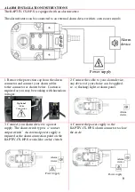
ALARM INSTALLATION INSTRUCTIONS 

The KAPTIV-CS-HP-S is equipped with an alarm feature.  
 
The alarm feature can be connected to an external alarm device with its own power supply. 


1. Remove the protection cap from the alarm 
connector and connect your alarm cables 
to the connector


as shown below. Caution is 

required as you may be working with hazardous 
voltages.


2. Connect the cable to your alarm device,  
any device of your choice can be applied.  
i.e. a (flashing) light or alarm panel. 


 3. Connect your alarm device to a power   
 supply. The alarm switch type is a “contact   
 output switch”. An external power supply is  
 required as the alarm connection point on the  
 KAPTIV-CS-HP-S works like a relay switch 
only.   


4. Connect the power supply to the  
KAPTIV-CS-HP-S alarm connector to close 
the circle. 
 

Power supply 

ALARM DEVICE 

POWER SUPPLY 


Optional 

Alarm 

Connection


Alarm 
device 


Power supply 
 

Alarm  
device 


Alarm 
device 


Power supply 

Alarm  
device 


Alarm  
device 


Power supply 

Содержание KAPTIV-CS-HP-S

Страница 1: ...pressed air systems up to 100 m3 min without the loss of compressed air The KAPTIV CS HP S is a high pressure stainless steel zero air loss drain with a pressure rating from 0 to 50 bar The compact robust industrial housing the 2 2 way direct acting valve the alarm NC and NO and the integrated mesh strainer make the KAPTIV CS HP S a reliable draining solution The alarm function can be connected to...

Страница 2: ...afe working practices and observe all regulations and legal requirements for safety when operating this product When handling operating or carrying out maintenance on this product personnel must employ safe engineering practices and observe all local health safety requirements regulations International users refer to regulations that prevail within the country of installation Most accidents which ...

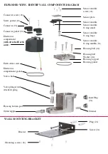
Страница 3: ...s compartment gasket Valve shaft Valve plunger with attached spring Housing bottom part Outlet nipple Sensor module screw 4x Sensor plate Sensor module Sensor module O ring small Sensor module O ring large Sensor module O ring middle 2x Housing bolt 4x Housing bolt Washer 4x Housing top part Housing gasket WALL MOUNTING BRACKET Plug 2x Screw 2x Bracket Mounting screws 4x Inlet Plug 2x Strainer ...

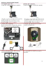
Страница 4: ...ugs 5a Top inlet connection If you choose to use the top inlet please locate a suitable condensate draining point on your compressed air system and connect your KAPTIV CS HP S as illustrated We strongly recommend to use flexible tubing to avoid damaging the unit by strong vibrations caused by the compressor The use of a ball valve is advisable 4 Use the four mounting screws to secure the KAPTIV CS...

Страница 5: ...r cable as shown 5 Power cable connection Remove the protection cap from the connector and connect your power cable as shown 9 Press and hold down the TEST button to check the valve function 10 Your KAPTIV CS HP S is ready for operation L Power Connection We advise to use the outlet nipple delivered with the KAPTIV CS HP S If it is necessary to use an alternative nipple make sure it has the correc...

Страница 6: ...cable to your alarm device any device of your choice can be applied i e a flashing light or alarm panel 3 Connect your alarm device to a power supply The alarm switch type is a contact output switch An external power supply is required as the alarm connection point on the KAPTIV CS HP S works like a relay switch only 4 Connect the power supply to the KAPTIV CS HP S alarm connector to close the cir...

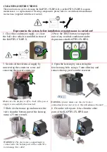
Страница 7: ... the KAPTIV CS HP S 3 Switch off the electrical supply by unscrewing the connector screw and removing the power connector Make sure the display is off to check if the power supply is successfully disconnected 4 Open the housing by unscrewing the four housing bolts using a 5 mm allen key and remove the top part from the reservoir WARNING please make sure the electronics compartment does not get wet...

Страница 8: ...erly to ensure IP65 rating and make sure the electronics have not been in contact with water WARNING Please make sure the cable connected to the electronics part does not get damaged while re assembling the components 9 Switch on the electrical supply by replacing the connector and connector screw max torque 1Nm Make sure the gasket is secured properly to ensure IP65 rating Make sure the display l...

Страница 9: ...9 SERVICE CHART Date Description Name ...

Страница 10: ...24VAC or 24VDC Connectors DIN 43650 B Serviceable valve Yes TEST feature Yes Environmental protection IP65 NEMA4 Integrated mesh strainer Yes Housing Material Stainless Steel Alarm feature type Contact output switch voltage free available in two versions A1 and A2 A1 Normally open contacts closed when in alarm phase Light on the drain is OFF when in operation and ON when in alarm mode A2 Normally ...

Отзывы: