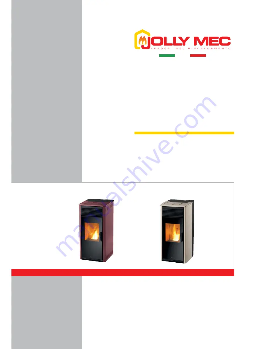
EKO Plus (6 kW)
STILE (8 kW)
SM063 EN REV06 2016_05
Air and
pellet STOVE
INSTALLATION, USE AND
MAINTENANCE MANUAL
To be kept by the purchaser
Страница 1: ...EKO Plus 6 kW STILE 8 kW SM063 EN REV06 2016_05 Air and pellet STOVE INSTALLATION USE AND MAINTENANCE MANUAL To be kept by the purchaser ...
Страница 2: ... VENTILATION 16 CHAP 06 POSITIONING AND CONNECTIONS FOR THE INSTALLER 17 06 1 SETTING UP OF EXTERNAL AIR INTAKES AND ELECTRIC CURRENT 17 06 2 PHASES OF ASSEMBLING DISASSEMBLING STOVE CLADDING 18 06 3 OPTIONALS 18 06 4 ELECTRICAL CONNECTIONS 18 06 5 ELECTRONIC CONTROL UNIT 19 06 6 EKO PLUS STILE STOVE CONTROL UNIT ELECTRICAL WIRING DIAGRAM 20 CHAP 07 USE AND MAINTENANCE FOR THE USER 21 07 1 STOVE O...
Страница 3: ...nical manual are owned by JOLLY MEC CAMINETTI S p A The descriptions and illustrations provided in the following publication are not binding JOLLY MEC CAMINETTI S p A reserves the right to make any modifications that may be deemed appropriate This manual cannot be given to third parties for perusal without the written permission of JOLLY MEC CAMINETTI S p A The technical directions for installatio...
Страница 4: ...information on the correct use of the product in accordance with the purposes for which it was designed and built It also provides information about loads commissioning re pair and maintenance of the stove in conformance with the limits set down by the manufacturer Conservation of the manual The installation and maintenance manual is an integral part of the product and must be conserved up to the ...
Страница 5: ...on the machine disconnect it from all energy sources in particular turn the electrical power switch to ZERO Prior to installation the user and installer are obliged to check that the mains electrical supply to which the machine will be con nected corresponds to the voltage on the identification plate see CHAP 04 2 PRODUCT IDENTIFICATION and that it is equipped with all suitable safety devices to c...
Страница 6: ...stem is sized so as to bear the maximum load required of the product and also that it is equipped with all suitable safety devices to classify the electrical system as COMPLIANT with applicable safety stan dards If this is not the case contact a Qualified Technician to adapt the system to required standards The power cord plug must be connected only AFTER the con clusion of the installation and as...
Страница 7: ...prescriptions in CHAP 02 of this manual and must wear work gloves and safety footwear For safety reasons unauthorised persons must not be in the area while the product is being moved The product must be moved only with a trolley or pallet fork and never with belts chains overhead cranes see CHAP 05 TECH NICAL DATA for the weight All parts of the packaging coming into contact with the crane belts o...
Страница 8: ...th relative temperatures Ambient temperature setting and viewing of the current ambient temperature on the display Output levels possibility to adjust the heat output to five different levels and to set the Silent mode Operating mode displays real time product operating modes Multi language choice of five European languages They are also fitted with PELLET hopper about 11 kg in capacity Humidifier...
Страница 9: ... replacing the top blind lid with another optional lid bearing a 100 mm diam hole through which the fumes are exhausted Combustion chamber door with BLACK silkscreen printed CERAMIC GLASS resistant to a temperature of 700 C Painted door open close handle Built in humidifier No claims can arise concerning the colour variations of the painted surfaces especially those of different materials and with...
Страница 10: ...g The shown label may be graphically different from the original 04 2 PRODUCT IDENTIFICATION 1 Product model 2 CE Marking 3 Year of Commissioning and Certification 4 Reference Standard 5 Performance declaration No 6 Product LOT no 7 Product Sales Code 8 Product Sales Number 9 Product label code Pursuant to European Regulation No 305 2011 manufacturers are now required to have the DoP Declaration o...
Страница 11: ...fume exhaust union the flue and pollute nature 05 1 HOMOLOGATION EN 14785 2006 CHAP 05 TECHNICAL DATA Description EKO PLUS STILE M U 353 Nominal burning output Qtot 6 53 8 56 kW 366 Nominal heat output P 6 13 8 0 kW 362 Reduced heat output P 3 60 3 60 kW 302 Nominal output consumption Bt 1 38 1 80 kg h 304 Reduced output consumption Bt 0 80 0 80 kg h 357 Maximum output dispersed into the environme...
Страница 12: ...ch guarantee conformity with the following values Powder 1 maximum through a 3 2 mm screen Apparent density 680 Kg m3 minimum Dimensions 6 mm diameter from 25 to 30 mm of maximum length Ash content 1 maximum Humidity 8 maximum Heating power 4 9 kWh Kg Packaging in eco compatible or biodegradable material sacks Store pellets at least 1 m from the stove fireplace Do not use pellets that are very har...
Страница 13: ...craper D Lid for loading pellets E LCD Display F Pellet hopper G Coaxial control H Fume pressure switch I Humidifier J Coaxial Control measuring point K Ash drawer L Iron firebox M Handle for opening the door N Combustion chamber door O Heating fan P Electrical heating element for lighting Q Combustion and fume exhauster fan ø80 mm R Pellet loading auger gear motor S Electronic control unit T Comb...
Страница 14: ...14 L 432 mm H 919 mm P 451 mm P1 515 mm EKO PLUS U M L 448 mm H 919 mm P 451 mm P1 515 mm STILE U M 05 4 DIMENSIONS in mm L P1 P H L P1 P H ...
Страница 15: ...t for connecting the equipment to the flue is forbidden Exhaust pipes must not run through rooms where the installation of combustion equipment is forbidden The union must be connected to the flue in such a way as to ensure they remain airtight when the appliance is operating in pressurised conditions and to avoid the formation of condensation and its conveyance to the appliance It has to be avoid...
Страница 16: ...es not work which will trigger the no depression alarm It is not possible to make corrections or reset the stove operating values to override the alarm 05 6 INSTALLATION ROOM VENTILATION According to reference regulation UNI10683 4 Pa depression must be verified between the installation room interior and exterior Pre pare adequate ventilation openings in the room where the product is installed to ...
Страница 17: ...t be installed in an area where the appliance itself gas exhaust pipes and flue can be easily accessed for cleaning The minimum distances to be maintained are shown in the te chnical drawings The lateral distance from the adjacent wall according to installation is to be maintained on both sides All measurements are in mm 1 Fume exhaust 2 Electric socket to be positioned 1250 mm max from the stove ...
Страница 18: ...o the CLADDING ASSEMBLY MANUAL for instructions on the cladding assembly phases 06 4 ELECTRICAL CONNECTIONS Electrical connections must be carried out by skilled per sonnel according to the regulations in force 2014 30 UE and 2014 35 UE Connect the 230Vac 50Hz line with the proper cable with plug supplied with the stove which powers up the control unit and all the stove s electrical components The...
Страница 19: ... appropriate for reading the correct ambient temperature The electric electronic elements also include certain safety systems FUME TEMPERATURE PROBE fitted inside the fume exhaust fan PRESSURE SWITCH fitted inside the fume exhaust fan PELLET HOPPER SAFETY THERMOSTAT fitted inside the PEL LET container it intervenes in situations where the temperature in side the stove is too high The Control Displ...
Страница 20: ...6 7 9 8 10 11 13 14 15 12 16 17 1 Number Description 1 User display 2 Electronic card 3 Bipolar switch 4 Electric power cord with schuko socket 5 Smoke fan 6 Electrical heating element 7 Exchange fan 8 Bulb type safety thermostat 9 Fume pressure switch Number Description 10 Pellet loader gear motor 11 Ambient probe 12 Smoke probe 13 2 way connector for remote probe or thermostat 14 Serial port 15 ...
Страница 21: ...ted on the upper part of the cladding The fireplace is equipped with an exchanger in steel and dual heat developing FIREFLECTOR closed in front by a door in ceramic glass The quantity of fuel the feeding of comburent air and the extraction of fumes are regulated with an electronic card in order to obtain a highly efficient combustion The control panel M is used to manage all operating functions se...
Страница 22: ... output button Button to change page within the Menu Page forward Display panel Displays the stove status messages Component reference icons DGT DIGIT Indicator box 1 2 3 4 5 6 7 8 9 Decal icon key Symbols are found on the left of the LCD display which refer to the electric electronic components installed on the stove and the presence of a DGT see pos 9 next to the icon means that the indicated co...
Страница 23: ...ng phase 3 PELLET preloading after the preheating phase a set amount of PELLETS are delivered to the firebox to ignite the first flame 4 Flame standby the fourth phase is a standby time required to heat the preloaded PELLETS and wait for ignition 5 Start up time when the flame is ignited the electronic control unit starts up where the fume temperature must reach a preset value in order for the sto...
Страница 24: ...ure must decrease to 1 0 C below the SET temperature The fan speed for the hot air exhausted through the grid depends on the output levels the higher the output level the faster the air will be pumped through the front grid Example of display message with the stove in RUNNING mode XXX WORK Example of display message with the stove in ECO mode xxx ECO YYY MODULAT Example of display message when adj...
Страница 25: ...n 1 or 2 to set START 1 time press button 4 to confirm 9 press button 1 or 2 to set STOP 1 time press button 4 to confirm 10 Set the operating power with buttons 1 or 2 Press button 4 to confirm 11 Set the required room temperature with buttons 1 or 2 Press button 4 to confirm 12 press button 1 or 2 to set START 2 time press button 4 to confirm 13 press button 1 or 2 to set STOP 2 time press butto...
Страница 26: ...ss button 3 4 to confirm 4 pressbutton1or2tochangethelanguage pressbutton4toconfirm 5 press button 3 to exit press repeatedly to reach the home page 1 2 3 4 6 Menu M2 1 001 XXX DELAY YYY TURN ON The DELAY Function settable from MENU 02 SET CHRONO con sents to set the offset time before switching on and after scheduled shutdown on the appliance When the appliance is OFF set DELAY TURN ON for deferr...
Страница 27: ...ended to enable the STD BY function only if the ambient conditions are favourable excessive start ups and switch offs during the day reduces the performance of the stove and leads to wasting of energy Menu 06 XXX YYY 1 2 3 4 6 Menu 06 XXX SET YYY DISPLAY User interface settings DISPLAY SETTINGS 1 button 4 2 press button 6 to reach the SET DISPLAY page press button 4 to confirm 3 pressbutton1or2toe...
Страница 28: ...a lower heat efficiency and vice versa ADJUST CHIMNEY use this setting when the draught conditions change Increase in cases of weak draught and vice versa WARNING Jolly Mec declines all liability regarding incorrect adjustments and setting that could cause the stove to malfunction Menu 08 XXX YYY 5 3 4 6 Menu 08 XXX STATE YYY STOVE Menu 8 consists of various pages that display information on the s...
Страница 29: ...number of exclusions of Coaxial Control system 7 press button 6 to go to page 13 which displays the alarms memory log Each alarm page shows how many times it was triggered and the date of the most recent event 8 press button 6 to move from one alarm page to the next 9 move on by pressing button 6 From page 18 to 21 the name the manufacturing date the lot and the serial number of the product are di...
Страница 30: ...ectly at the head office of Jolly Mec Caminetti S p A If the glass becomes very dirty with visible blackening while operating on pellets possible causes could be low draught by the flue clean the flue or check its characteristics Insufficient comburent air add more air with the combustion fan clean the air intake Note that it is necessary to burn about 1 31kg of pellets per hour in order to achiev...
Страница 31: ...turning smoke enter the pellet hopper Reposition the pellet container perfectly Glass cleaning daily Clean the glass daily with a damp sponge or paper hand towels If the glass becomes dirty with black smoke the pellet basket is probably dirty or the combustion air must be increased Take care not to use products that are too aggressive in order not to ruin the paint If the stove requires more frequ...
Страница 32: ...s re commended to vacuum the drawer housing to remove any ash residue 6 Removing the firebox With the combustion chamber door open lift the firebox upwards to remove it see Fig 7 It is compulsory to clean the firebox thoroughly making sure no holes are clogged Before replacing the firebox check there is no ash or dirt in the firebox housing Vacuum this area tho roughly too 7 Positioning the firebo...
Страница 33: ... see Fig 14 10 Cleaning the cladding As per the ceramic glass do not spray products directly onto the cladding see Fig 15 take a damp cloth see Fig 16 and use it to clean the cladding see Fig 17 and Fig 18 Use of abrasive and or corrosive chemical products can damage the painted or ceramic parts and are reason for invalidation of the warranty on these parts ...
Страница 34: ...anying it until it has been completely extracted from the combustion chamber see Fig 21 12 Resetting the safety thermostat see also par 07 7 Unscrew the black hood fastened to the galvanised section at the back of the stove see Fig 22 Press the white button see Fig 23 funtil you hear it CLICK into the safety reset position Refit the black hood 13 Connecting the power socket Before connecting the p...
Страница 35: ...s you may have we invite you to contact the specialised Technical Service Center through your retailer Scheduled maintenance must include WARNING To carry out these operations the stove must be disconnected from the mains wait until the stove is cold and comply rigorously with the safety regulations in force Cleaning the main stove body to be verified according to use Cleaning of the flue once a y...
Страница 36: ...ean it thoroughly and check it is clean each time you start it up The basket is positioned incorrectly The resistance is faulty The pellets burn incorrectly and unburnt elements gather in the basket the glass looks black and is very dirty The amount of pellets loaded in the basket for the various output modes does not correspond to the amounts indicated in the Technical Specifications see CHAP 05 ...
Страница 37: ...r rpm Check that all the electrical connections are in order Check to see if the combustion fan is very dirty Check to see if a foreign body has accidentally been caught up in the fan or the external motor AL05 NO LIGHTIN The START UP DELTA setting has not been reached within the maximum startup time Check the efficiency of the electrical element Check that the element guide tube is clean Always c...
Страница 38: ...ry to replace the motherboard or the gear motor AL12 ENCODER AUGER The control unit does not detect the correct number of revolutions of the gear motor Contact the specialised Technical Service Center AL13 FLAME ANOMAL During the stabilisation phase Flame present the fumes temperature does not exceed the Pr18 FLAME DELTA Check the pellet load and fume exhaust fan values they may be incorrect and n...
Страница 39: ... is not correct read Check probe wiring If correct replace the probe AL18 PELLET LEVEL If the level sensor is installed on the model it signals that the pellet level in the container is lower than the sensor Fill the container with fuel Each safety alarm shuts down the stove However not all alarms indicate actual danger must are just warnings or alerts To resume normal operating conditions press K...
Страница 40: ...e machine must be disposed of in a manner that complies with the laws in force and the environment 09 2 DISPOSAL OF THE MACHINE The stove is mainly composed of ferrous materials but it may also contain piping insulating materials electrical parts etc refractory materials When you no longer intend to use the stove ever again do not dispose of it irresponsibly Remember to empty the circuit completel...
Страница 41: ...41 NOTES ...
Страница 42: ...42 ...
Страница 43: ...43 ...
Страница 44: ...Via S Giuseppe 2 24060 Telgate Bg Italy Tel 39 035 83 59 211 Fax 39 035 83 59 203 www jolly mec it info jolly mec it SM063 EN REV06 2016_05 ...