background image

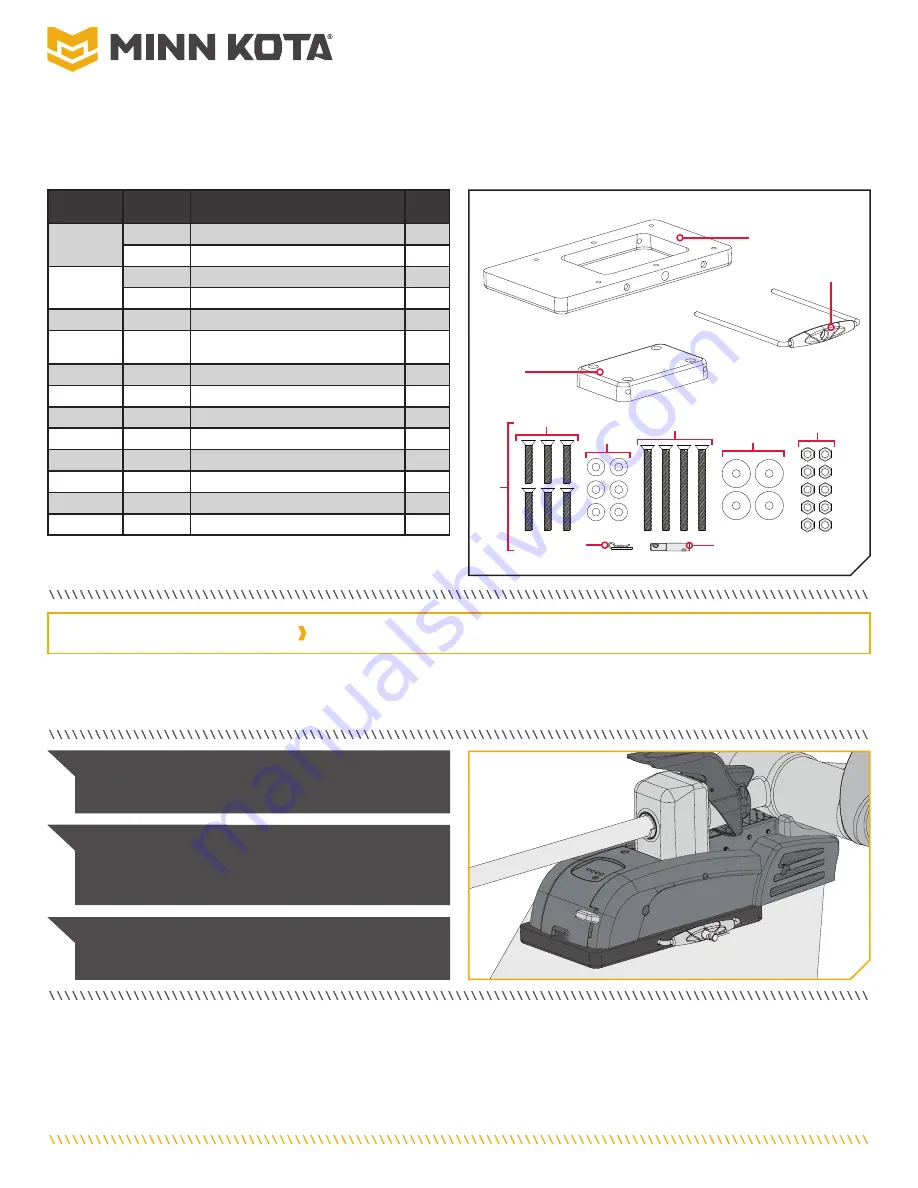
MKA-21/RTA-17  

QUICK RELEASE BRACKET

1854021 & 1854017

Item / 

Assembly

Part #

Description

Qty.

2

2371965

PLATE-INNER PD/AP QCK REL.

1

2371966

PLATE-INNER PD/AP QRB BLK.

1

4

2371967

PLATE-OUTER PD/AP QCK REL.

1

2371968

PLATE-OUTER PD/AP QRB BLK.

6

2990906

HANDLE ASSY PD/AP QRB.

1

A

Includes 8-20

2994848

BAG ASSY PD/AP QRB

1

8

2372631

PIN-PADLOCK PD/AP QCK REL.

1

10

2260800

CLIP-HAIR SPRING,SS,MAX BG

1

12

2373480

SCREW-1/4-20 X 1 1/2 PFH SS

6

14

2371712

WASHER-FLAT 9/32 X 5/8 X 1/16

6

16

2373482

SCREW-1/4-20 X 3” PFH SS

4

18

2261713

WASHER-1/4 FLAT 18-8 SS

4

20

2073100

NUT-HEX 1/4-20 NYLOC-JAM SS

10

2374917

INSTRUCTIONS PD/AP QRB

1

The MKA-21 is recommended for use with Minn Kota

®

 Ulterra™, Terrova

®

, PowerDrive™, PowerDrive V2, and Pontoon PowerDrive™ 

freshwater trolling motors and the Deckhand 40. The RTA-17 is recommended for use with Minn Kota

® 

RT Ulterra™, RT Terrova

®

, RT 

PowerDrive™ and RT PowerDrive V2 saltwater trolling motors. 

Do not use with motors equipped with a shaft 72” or greater. Do not use with 

112lb thrust motors.

NOTICE:

 Do not use with motors equipped with a shaft 

72” or greater. Do not use with 112lb thrust motors.

NOTICE:

 It is recommended to have a second person 

help with this installation. 

 Not shown on Parts Diagram. 

 This part is included in an assembly and cannot be ordered individually. 

2

2

4

4

12

12

16

16

14

14

18

18

20

20

A

A

6

6

10

10

8

8

TOOLS AND RESOURCES REQUIRED

•  Drill
•  Drill bit 17/64”
•  #2 or #3 Philips Screwdriver

•  Awl, pencil or similar marking tool
•  Scissors 

•  A second person to help with  

the installation

NOTICE:

 Images are a graphical representation and 

may vary from your motor. 

Save the box! A template for 

installation is printed on the inside of the box.

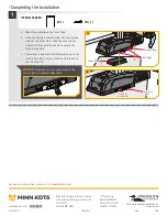
Complete Typical 

Complete Typical 

Installation

Installation

1  |  minnkotamotors.com

©2021 Johnson Outdoors Marine Electronics, Inc.

Содержание 1854017

Страница 1: ... is recommended for use with Minn Kota RT Ulterra RT Terrova RT PowerDrive and RT PowerDrive V2 saltwater trolling motors Do not use with motors equipped with a shaft 72 or greater Do not use with 112lb thrust motors NOTICE Do not use with motors equipped with a shaft 72 or greater Do not use with 112lb thrust motors NOTICE It is recommended to have a second person help with this installation Not ...

Страница 2: ...e edge of the boat Make sure the area under the mounting location is flat clear to drill holes and install nuts and washers Recruit a second person to help with the installation as an unsecured motor will tip when deployed and when left unattended Ulterra PowerDrive or Terrova Ulterra Ulterra RT Ulterra RT Ulterra PowerDrive Pontoon PowerDrive Pontoon PowerDrive PowerDrive RT PowerDrive RT PowerDr...

Страница 3: ... obstructions when positioning the motor on and off the composite bracket The exact placement of the motor and bracket when mounting may vary depending on the boat boat deck and which base extrusion or bracket the bracket is being mounted to Bow of Bow of Boat Boat Outboard Outboard Inboard Inboard Port Port Starboard Starboard ITEM S NEEDED 4 x 1 2 x 1 6 x 1 8 x 1 1b c Once an orientation for the...

Страница 4: ...he Power Cables from the battery are disconnected or that the breaker if equipped is off b Remove the four sideplate screws using a 3 Phillips screwdriver Two of these screws will be located on each side of the mount c Remove the Right Sideplate d Swing the Left Sideplate out and away from the Base Extrusion Removing the sideplates exposes the Mounting Holes in the Base Extrusion 2 Right Sideplate...

Страница 5: ...f the Outer Plate and then through the Base Extrusion Place a Flat Washer on the end of each bolt and then secure each Screw with a Nylock Nut g Re install both side covers Secure the Screws using a 3 Phillips Screwdriver Motor Base Motor Base Extrusion Extrusion Outer Outer Plate Plate Nylock Nylock Nut Nut Flat Flat Washer Washer Inboard Inboard Outboard Outboard Stainless Stainless Steel Screw ...

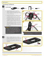
Страница 6: ...w Nylock Nut Nylock Nut Flat Flat Washer Washer 1 a Position the Pontoon Hand Control Bracket over the Outer Plate Item 4 and mount the Bracket using only the four holes that are farthest Outboard The two holes closest inboard are not used to install the Bracket b Take four x 1 Stainless Steel Screws Item 12 and insert them from the bottom of the Outer Plate through the Pontoon Hand Control Bracke...

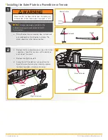
Страница 7: ...n place Once the e clips are removed slide the Extension Damper off the Damper Pins to expose the left rear Mounting Hole Set the two e clips and Extension Damper in a safe place so they are not misplaced before they are reassembled later in the installation E clips E clips Extension Extension Damper Damper Damper Pins Damper Pins Extension Extension Damper Damper E clip E clip E clip E clip Mount...

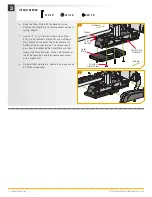
Страница 8: ...ra The Stainless Steel Screws Item 12 will still be used Instead the Clipped Washers 2201725 included in the mounting hardware that came with the Ulterra motor should be used NOTICE To prevent seizing of the stainless steel hardware do not use high speed installation tools Wetting the screws or applying an anti seize may help prevent seizing ITEM S NEEDED 4 x 1 12 x 3 f Place the hardware on the D...

Страница 9: ...s E clips E clips Extension Damper Extension Damper Damper Pins Damper Pins 6 i Replace the Right Sideplate j Replace the Left Sideplate k Replace the four sideplate Screws using a 2 or 3 Phillips Screw Driver Left Sideplate Left Sideplate Screw Screw Screw Screw Screw Screw Right Sideplate Right Sideplate Screw Screw 7 7i 7j 9 minnkotamotors com 2021 Johnson Outdoors Marine Electronics Inc ...

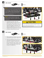
Страница 10: ...ully pull the glued edges apart and open the box so that it lays flat On the inside of the box a template is printed to help locate mark and drill the holes for the Inner Plate Cut the template out and place it on the bow Align it with the markings that were made while checking handle and motor clearances Make sure that the orientation of the Outer Plate in the template matches the orientation of ...

Страница 11: ... 20 x 3 Stainless Steel Screws Item 16 four Flat Washers Item 18 and four Nylock Nuts Item 20 The Screws should pass through the Inner Plate then the Bow then the Flat Washers and Nylock Nuts NOTICE If the Handle Assembly does not slide easily into place after completing the installation it may be necessary to drill out the Handle Rod Holes using a letter F 257 drill bit Stainless Stainless Steel ...

Страница 12: ...r onto the Inner Plate b Slide the Handle Assembly Item 6 into the rod holes of the Outer Plate Slide the Hair Clip Pin Item 10 through the Lock Pin to secure the Handle Assembly c Your motor is now mounted Always make sure the Handle Assembly is fully inserted and retained by the Hair Clip Pin Inner Plate Inner Plate Outer Plate Outer Plate Handle Handle Assembly Assembly Hair Clip Hair Clip Pin ...

Страница 13: ...erraMC RT TerrovaMD RT PowerDriveMC et RT PowerDrive V2 Ne pas utiliser avec des moteurs équipés d un arbre de 72 po 183 cm ou plus Ne pas utiliser avec des moteurs offrant une poussée de 112 lb 51 kg AVIS Ne pas utiliser avec des moteurs équipés d un arbre de 72 po 183 cm ou plus Ne pas utiliser avec des moteurs offrant une poussée de 112 lb 51 kg AVIS On recommande qu une deuxième per sonne vous...

Страница 14: ...one sous l emplacement de montage est dégagée et plate pour percer des trous et installer des rondelles et des écrous Recrutez une deuxième personne pour aider avec l installation car un moteur non fixé basculera lorsqu il est déployé et lorsqu il est laissé sans surveillance Ulterra PowerDrive ou Terrova Ulterra Ulterra et et RT Ulterra RT Ulterra PowerDrive Pontoon PowerDrive Pontoon PowerDrive ...

Страница 15: ... lorsque vous le placez sur le support en composite et que vous l enle vez L emplacement précis du moteur et du support peut varier selon le bateau le pont du bateau et l extrusion de la base ou le support auquel est monté le support Étrave du Étrave du bateau bateau Hors bord Hors bord En bord En bord Bâbord Bâbord Tribord Tribord ARTICLE S REQUIS 4 x 1 2 x 1 6 x 1 8 x 1 1b c Une fois le choix de...

Страница 16: ...batterie sont déconnectés ou que le disjoncteur le cas échéant est en position arrêt b Retirez les quatre vis de la plaque latérale en utilisant un tournevis cruciforme nº 3 Deux de ces vis seront situées de chaque côté du support c Enlevez la plaque latérale droite d Faites pivoter la plaque latérale gauche en l éloignant de l extrusion de la base Le retrait des plaques latérales expose les trous...

Страница 17: ... la plaque externe et ensuite à travers l extrusion de la base Placez une rondelle plate au bout de chaque boulon et fixez chaque vis avec un écrou Nylock g Re installez les deux couvercles latéraux Fixez les vis à l aide d un tournevis cruciforme nº 3 Extrusion Extrusion de la base de la base du moteur du moteur Plaque Plaque externe externe Écrou Nylock Écrou Nylock Rondelle Rondelle plate plate...

Страница 18: ...elle Rondelle plate plate 1 a Positionnez le support de commande manuelle Pontoon au dessus de la plaque externe article nº 4 et montez le support en utilisant seulement les quatre trous qui sont le plus loin hors bord Les deux trous les plus proches en bord ne sont pas utilisés pour installer le support b Prenez quatre vis en acier inoxydable de po x 1 po 6 4 mm x 38 1 mm article nº 12 et insérez...

Страница 19: ...ation de l amortisseur des tiges d amortisseur pour exposer le trou de montage arrière gauche Déposez les deux serre câbles et la prolongation de l amortisseur dans un endroit sûr afin de ne pas les perdre avant d être réassemblés plus tard dans l installation Serre câbles Serre câbles Prolongation de Prolongation de l amortisseur l amortisseur Tiges Tiges d amortisseur d amortisseur Prolongation ...

Страница 20: ...erie de montage fournie avec le moteur Ulter ra devraient être utilisées à la place AVIS Pour prévenir le grippage de la quincaillerie en acier inoxydable n utilisez pas d outils haute vitesse pour l installation Le fait de mouiller les vis ou d appliquer un produit antigrippant peut aider à prévenir qu elles grippent f Placer la quincaillerie dans les trous de montage sur le côté du support où se...

Страница 21: ... Serre câbles Prolongation de l amortisseur Prolongation de l amortisseur Tiges d amortisseur Tiges d amortisseur 6 k Replacez la plaque latérale droite l Replacez la plaque latérale gauche m Replacez les quatre vis de la plaque latérale en utilisant un tournevis cruciforme nº 2 ou nº 3 Plaque latérale Plaque latérale gauche gauche Vis Vis Vis Vis Vis Vis Plaque latérale Plaque latérale droite dro...

Страница 22: ...ollés puis ouvrez la boîte pour qu elle soit à plat À l intérieur de la boîte se trouve un gabarit imprimé pour aider à localiser marquer et percer les trous pour la plaque interne Découpez le gabarit et placez le sur l étrave Alignez le avec les marques qui sont faites tout en vérifiant les dégagements pour la poignée et le moteur Assurez vous que l orientation de la plaque externe dans le gabari...

Страница 23: ... po 6 4 mm 20 x 76 2 mm article nº 16 quatre rondelles plates article nº 18 et quatre écrous Nylock article nº 20 Les vis devraient passer à travers la plaque interne puis l étrave ensuite les rondelles plates et les écrous Nylock AVIS Si l ensemble poignée ne glisse pas facile ment en place après l installation il pour rait être nécessaire de forer les trous de la tige de la poignée avec une mèch...

Страница 24: ...ensemble poignée article nº 6 dans les trous de la tige de la plaque externe Faites glisser la goupille Béta article nº 10 à travers la goupille de verrouillage pour fixer l ensemble poignée c Votre moteur est maintenant monté Assurez vous toujours que l ensemble poignée est entièrement inséré et retenu par la goupille Béta Plaque Plaque interne interne Plaque Plaque externe externe Ensemble Ensem...

Отзывы: