


JOHNSON CONTROLS
18
FORM 160.75-N1
ISSUE DATE: 4/30/2014
SECTION 2 - INSTALLATION
REFRIGERANT RELIEF PIPING
Each unit is equipped with pressure relief valves lo-
cated on the condenser and on the evaporator for the
purpose of quickly relieving excess pressure of the re-
frigerant charge to the atmosphere as a safety precau-
tion in case of an emergency, such as fire.
Refrigerant relief vent piping (by others), from the re-
lief valves to the outside of the building, is required
by code in most areas and should be installed on all
chillers. The vent line should be sized in accordance
with the ANSI/ASHRAE-15, or local code. The vent
line must include a dirt trap in the vertical leg to in-
tercept and permit clean out and to trap any vent stack
condensation. The piping MUST be arranged to avoid
strain on the relief valves, using a flexible connection,
if necessary.
UNIT PIPING
Compressor lubricant piping and system external pip-
ing are factory installed on all units shipped assembled.
On units shipped dismantled, the following piping
should be completed under the supervision of the John-
son Controls representative: (1) the lubricant piping to
oil sump and oil evaporator and system oil return con-
nections using material furnished. Refer to
Installation
- Unit (Form 160.75-N3).
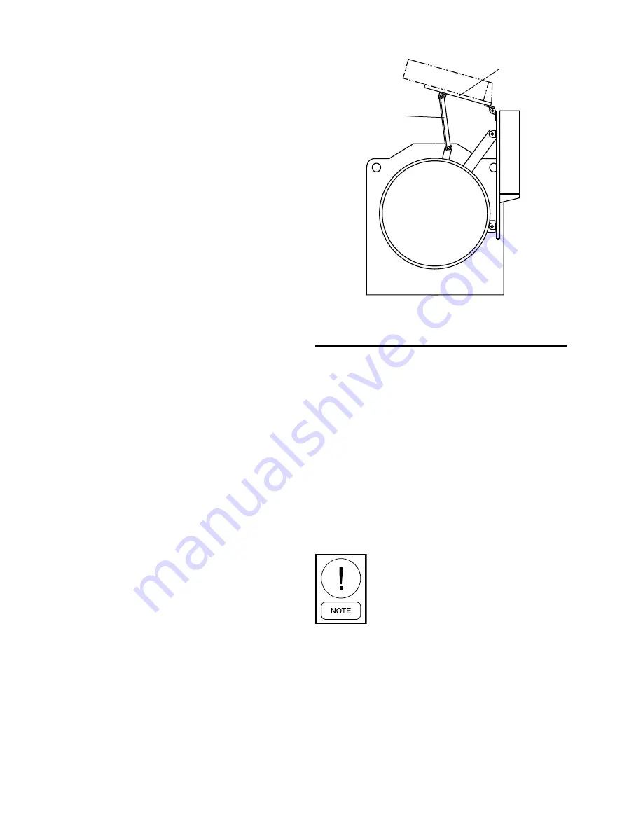
CONTROL PANEL POSITIONING
On large YK chillers equipped with H9 and K1-K7
compressors, the control panel height can be adjusted.
Chillers equipped with P and Q compressors the
control panel height is NOT adjustable.
The OptiV-
iew™ Control Center is placed in a position above the
evaporator for shipping. To move the control center
into position for operation, proceed as follows:
1. While supporting the control center, remove the
hardware between the support arms and the evap-
orator.
2. Swing the control center into a vertical position.
3. Slide the control center down the guide rails to the
proper position. Tighten securely.
4. Discard unused hardware.
CONTROL WIRING
On units shipped disassembled, after installation of the
control center, control wiring must be completed be-
tween unit components and control center, solid state
starter, or variable speed drive, when used, using wir-
ing harnesses furnished. Refer to
Installation - Unit
(Form 160.75-N3).
Field wiring connections for commonly encountered
control modifications (by others) if required, are
shown on
Wiring Diagram – Unit (Style G) Field Con-
trol Modifications (Form 160.75-PW4).
No deviations in unit wiring from that
shown on drawings furnished shall be
made without prior approval of the John-
son Controls representative.
POWER WIRING
Chiller with Electro-Mechanical Starter
A 115 volt – single phase – 60 or 50 Hertz power sup-
ply of 20 amperes must be furnished to the control
center, from the control transformer (2 KVA required)
included with the compressor motor starter. Do NOT
make final power connections to control center until
approved by YORK representative.
SUPPORT
ARMS
PANEL
TRACK
FIGURE 9 -
CONTROL PANEL POSITIONING
(H9, K1-K7)
LD03826
Содержание YORK YK Style G OPTIVIEW
Страница 38: ...JOHNSON CONTROLS 38 FORM 160 75 O1 111 NOTES ...
Страница 242: ...FORM 160 54 O1 ISSUE DATE 9 10 2014 JOHNSON CONTROLS 202 SECTION 3 DISPLAY MESSAGES THIS PAGE INTENTIONALLY LEFT BLANK ...
Страница 258: ...FORM 160 54 O1 ISSUE DATE 9 10 2014 JOHNSON CONTROLS 218 NOTES ...
Страница 266: ...JOHNSON CONTROLS 6 FORM 160 75 N1 ISSUE DATE 4 30 2014 THIS PAGE INTENTIONALLY LEFT BLANK ...