WARNING
External wiring, unless specified as an optional connection in the manufacturer’s product line, is not
to be connected inside the control cabinet. Devices such as relays, switches, transducers and controls
and any external wiring must not be installed inside the micro panel. All wiring must be in accordance
with Johnson Controls’ published specifications and must be performed only by a qualified electrician.
Johnson Controls will not be responsible for damage/problems resulting from improper connections
to the controls or application of improper control signals. Failure to follow this warning will void the
manufacturer’s warranty and cause serious damage to property or personal injury.
Changeability of this document
In complying with Johnson Controls’ policy for continuous product improvement, the information
contained in this document is subject to change without notice. Johnson Controls makes no
commitment to update or provide current information automatically to the manual or product
owner. Updated manuals, if applicable, can be obtained by contacting the nearest Johnson Controls
Service office or accessing the Johnson Controls website at
https://docs.johnsoncontrols.com/bas/
It is the responsibility of rigging, lifting, and operating and service personnel to verify the
applicability of these documents to the equipment. If there is any question regarding the
applicability of these documents, rigging, lifting, and operating and service personnel should verify
whether the equipment has been modified and if current literature is available from the owner of
the equipment prior to performing any work on the chiller.
Revision notes
Revisions made to this document are indicated in the following table. These revisions are to
technical information, and any other changes in spelling, grammar, or formatting are not included.
Affected pages
Description
38, 39
Planned Maintenance information added
Associated literature
Manual description
Form number
Operation – Variable Speed Drive – TM Model
160.00-O1
Operation and Maintenance – Solid State Starter (Mod B)
160.00-O2
Operation – Variable Speed Drive – VSD and LVD Model
160.00-O4
Floor Mounted MV SSS – Operation
160.00-O5
Unit Mounted MV SSS – Operation
160.00-O7
Operation – Variable Sped Drive – HYP Model
160.00-O10
Installation – Unit
160.75-N1
OptiView™ Control Center – Operation and Maintenance
160.54-O1
Wiring Diagram – Field Connections for YK Chiller (Style G) OptiView™ Control
Center with Remote Low or Medium Voltage EMS or Unit Mounted Low or Medium
Voltage SSS
160.75-PW1
Wiring Diagram – Field Connections for YK Chiller (Style G) OptiView™ Control
Center with Remote Medium Voltage SSS
160.75-PW2
Model YK Style G R-134a or R-513A
6
Содержание York OptiView YK G Series
Страница 2: ...2 Model YK Style G R 134a or R 513A...
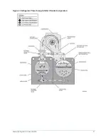
Страница 10: ...Figure 3 Refrigerant flow through chiller falling film evaporator Model YK Style G R 134a or R 513A 10...
Страница 11: ...Figure 4 Refrigerant flow through chiller flooded evaporator 11 Model YK Style G R 134a or R 513A...
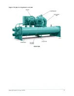
Страница 21: ...Figure 10 System components rear view 21 Model YK Style G R 134a or R 513A...
Страница 22: ...Figure 11 Schematic drawing YK compressor lubrication system Model YK Style G R 134a or R 513A 22...


