JOHNSON CONTROLS
11
SECTION 2 - INSTALLATION
FORM 160.43-NM4
ISSUE DATE: 11/12/2012
2
WIRING
Disconnect all supply circuits before wir-
ing LPCO control.
Wire control according to national and
local electrical codes. Maximum wire size
is #14 awg.
The recommended tightening torque for
field wiring terminals is 7 to 17 in-lbs.
Electrical ratings stated in literature and
on nameplates must never be exceeded -
overload on a switch can cause failure on
the first cycle.
A 7/8 in. dia. hole for conduit connection is provided
on the left hand side of the bracket plate. Refer to Fig-
ures 2 and 3.
Keep the wires as short as possible to prevent inter-
ference with the plunger or the adjustable differential
switch wheel or obstructing enclosure cover closure.
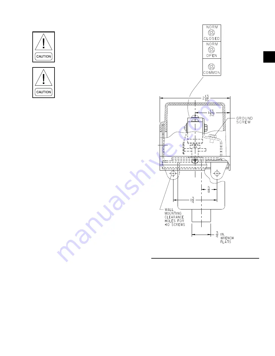
A grounding screw (green) is provided on the right
hand side at the rear of the switch bracket. Refer to
Figure 3.
The three switch terminals are clearly labeled COM-
MON, NORMALLY OPEN and NORMALLY
CLOSED. Refer to Figures 3 and 4.
1.
Remove enclosure cover first by removing the one
captive screw located on the front of the cover.
Refer to Figures 2 and 3.
2. Install kit supplied plastic snap bushing (YORK
p/n 025 10147 000) into 025 45742 LPCO control
7/8 in. dia. conduit hole. Refer to Figures 2 and 3.
3. Replacing a former 225 15443 002 LPCO control.
Proceed to step 4 if replacing a 025 45742 LPCO
control
a. To reach the LPCO control 025 45742 switch
terminals, the preexisting wires (47, 48 and
49) may need to be relocated through the
cabinet middle conduit fitting containing the
high pressure control wires. Reroute LPCO
wiring as necessary.
FIGURE 3 -
PRESSURE CONTROL FRONT VIEW
LD12523
b. The Faston type push-on terminal connectors
used with the former 225 15443 002 LPCO
control wiring are to be cut off and replaced
with kit supplied crimp-on insulated spring
spade (YORK p/n 025 18732 000) terminal
connectors.


