


JOHNSON CONTROLS
48
FORM 201.23-NM2
ISSUE DATE: 3/9/2015
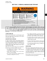
SECTION 4 - INSTALLATION
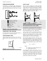
POWER WIRING
All electrical wiring should be carried out in accor-
dance with local regulations. Route properly sized
cables to cable entries on the unit.
In accordance with local codes, NEC codes and U.L.
Standards, it is the responsibility of the user to install
over current protection devices between the supply
conductors and the power supply terminals on the unit.
To ensure that no eddy currents are set up in the power
panel, the cables forming the 3-phase power supply
must enter via the same cable entry.
All sources of supply to the unit must be
taken via a common point of isolation (not
supplied by Johnson Controls).
Copper power wiring only should be used for supply-
ing power to the chiller. This is recommended to avoid
safety and reliability issues resulting from connection
failure at the power connections to the chiller. Alumi-
num wiring is not recommended due to thermal char-
acteristics that may cause loose terminations result-
ing from the contraction and expansion of the wiring.
Aluminum oxide may also build up at the termination
causing hot spots and eventual failure. If aluminum
wiring is used to supply power to the chiller, AL-CU
compression fittings should be used to transition from
aluminum to copper. This transition should be done in
an external box separate to the power panel. Copper
conductors can then be run from the box to the chiller.
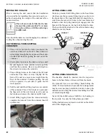
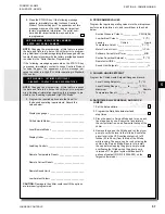
POWER SUPPLY WIRING
Units require only one 3-phase supply, plus earth
ground.
Connect the 3-phase supplies to the terminal block or
optional circuit breaker located in the panel using lug
sizes detailed in
Connect a ground wire from the chiller panel ground
lug to the incoming line supply ground.
115VAC CONTROL SUPPLY TRANSFORMER
A 3-wire high voltage to 115VAC supply transformer
is standard in the chiller. This transformer is mounted
in the cabinet and steps down the high voltage supply
to 115VAC to be used by the controls, VSD, Feed and
Drain Valve Controller, valves, solenoids, heaters, etc.
The high voltage for the transformer primary is taken
from the chiller input. Fusing is provided for the trans-
former.
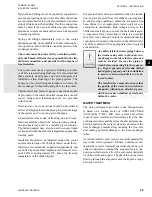
Removing high voltage power to the
chiller will remove the 115VAC supply
voltage to the control panel circuitry and
the evaporator heater. In cold weather,
this could cause serious damage to the
chiller due to evaporator freeze-up. Do
not remove power unless alternate means
are taken to ensure operation of the
evaporator heater.
CONTROL PANEL WIRING
All control wiring utilizing contact closures to the con-
trol panel terminal block is nominal 115VAC and must
be run in shielded cable, with the shield grounded at
the panel end only, and run in water tight conduit. Run
shielded cable separately from mains cable to avoid
electrical noise pick-up. Use the control panel cable
entry to avoid the power cables.
Voltage free contacts connected to the panel must be
suitable for 115VAC-10ma (gold contacts recommend-
ed). If the voltage free contacts form part of a relay
or contactor, the coil of the device must be suppressed
using a standard R/C suppressor. The above precau-
tions must be taken to avoid electrical noise, which
could cause a malfunction or damage to the unit and its
controls.
Содержание YCIV0157
Страница 18: ...JOHNSON CONTROLS 18 FORM 201 23 NM2 ISSUE DATE 3 9 2015 SAFETY SYMBOLS THIS PAGE INTENTIONALLY LEFT BLANK ...
Страница 38: ...JOHNSON CONTROLS 38 FORM 201 23 NM2 ISSUE DATE 3 9 2015 THIS PAGE INTENTIONALLY LEFT BLANK ...
Страница 42: ...JOHNSON CONTROLS 42 FORM 201 23 NM2 ISSUE DATE 3 9 2015 THIS PAGE INTENTIONALLY LEFT BLANK ...
Страница 50: ...JOHNSON CONTROLS 50 FORM 201 23 NM2 ISSUE DATE 3 9 2015 THIS PAGE INTENTIONALLY LEFT BLANK ...
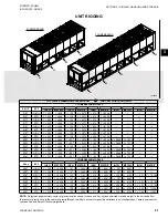
Страница 104: ...JOHNSON CONTROLS 104 FORM 201 23 NM2 ISSUE DATE 3 9 2015 SECTION 6 TECHNICAL DATA Panel Layout 2 Compressor Models ...
Страница 105: ...JOHNSON CONTROLS 105 SECTION 6 TECHNICAL DATA FORM 201 23 NM2 ISSUE DATE 3 9 2015 THIS PAGE INTENTIONALLY LEFT BLANK ...
Страница 115: ...JOHNSON CONTROLS 115 SECTION 6 TECHNICAL DATA FORM 201 23 NM2 ISSUE DATE 3 9 2015 THIS PAGE INTENTIONALLY LEFT BLANK ...
Страница 119: ...JOHNSON CONTROLS 119 SECTION 6 TECHNICAL DATA FORM 201 23 NM2 ISSUE DATE 3 9 2015 THIS PAGE INTENTIONALLY LEFT BLANK ...
Страница 333: ...JOHNSON CONTROLS 333 FORM 201 23 NM2 ISSUE DATE 3 9 2015 NOTES ...


