


JOHNSON CONTROLS
169
SECTION 6 - TECHNICAL DATA
FORM 201.23-NM2
ISSUE DATE: 3/9/2015
6
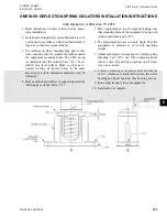
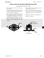
SLRS SEISMIC ISOLATOR INSTALLATION AND ADJUSTMENT
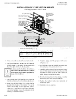
To Install and Adjust Mounts
1. Supports for mountings must be leveled to instal-
lation's acceptable tolerances.
2. Mountings not subjected to seismic or wind forces
do not require bolting to supports.
3. Mountings subjected to seismic or wind forces
must be bolted or welded in position.
4. If mountings are welded in position, remove low-
er friction pad before welding.
5. Set mountings with top channels held in place by
the lower restraining nuts and limit stops.
6. Place equipment on mountings and secure by
bolting or welding.
7. Hold lower restraining nut in place and turn ver-
tical limit stop bolt counter-clockwise until there
"D" Tap - 4 Holes unless
otherwise requested
Adjustment
Bolt
Vertical Limit
Stops-Out of
contact during
normal operation
Non-Skid Neoprene Pad-
Pad can be removed if
mounts are welded
into position.
Enclosed
Steel
Housing
Internal
Neoprene
Acoustical
Pad
Lower
Restraining
Nut
Rubber
Snubbing
Collar
MBD -Max
Bolt
Diameter
SHIPPED INSTALLED
A TER AD
STMENT
4"
"
LIMIT STOP
BOLT
LO ER
RESTRAININ
BOLTS
LD10568
Units shipped before June 15, 2008
is a 1/8" gap between the bolt head and the steel
washer.
8. Turn adjustment bolt 8 turns on each mount.
9. Take one additional complete turn on each adjust-
ment bolt in sequence until the top plate lifts off
of the lower restraining nuts. Take no additional
turns on that mount. Continue with equal turns on
the other mounts until the top plates lift off of the
lower restraining nuts of all mounts.
10. Hold the limit stop bolt in place and turn the low-
er restraining nut clockwise and tighten it against
the stanchion. Repeat the same procedure on all
mounts.
11.
Top plate should remain at a fixed elevation, plus
or minus 1/8".
Содержание YCIV0157
Страница 18: ...JOHNSON CONTROLS 18 FORM 201 23 NM2 ISSUE DATE 3 9 2015 SAFETY SYMBOLS THIS PAGE INTENTIONALLY LEFT BLANK ...
Страница 38: ...JOHNSON CONTROLS 38 FORM 201 23 NM2 ISSUE DATE 3 9 2015 THIS PAGE INTENTIONALLY LEFT BLANK ...
Страница 42: ...JOHNSON CONTROLS 42 FORM 201 23 NM2 ISSUE DATE 3 9 2015 THIS PAGE INTENTIONALLY LEFT BLANK ...
Страница 50: ...JOHNSON CONTROLS 50 FORM 201 23 NM2 ISSUE DATE 3 9 2015 THIS PAGE INTENTIONALLY LEFT BLANK ...
Страница 104: ...JOHNSON CONTROLS 104 FORM 201 23 NM2 ISSUE DATE 3 9 2015 SECTION 6 TECHNICAL DATA Panel Layout 2 Compressor Models ...
Страница 105: ...JOHNSON CONTROLS 105 SECTION 6 TECHNICAL DATA FORM 201 23 NM2 ISSUE DATE 3 9 2015 THIS PAGE INTENTIONALLY LEFT BLANK ...
Страница 115: ...JOHNSON CONTROLS 115 SECTION 6 TECHNICAL DATA FORM 201 23 NM2 ISSUE DATE 3 9 2015 THIS PAGE INTENTIONALLY LEFT BLANK ...
Страница 119: ...JOHNSON CONTROLS 119 SECTION 6 TECHNICAL DATA FORM 201 23 NM2 ISSUE DATE 3 9 2015 THIS PAGE INTENTIONALLY LEFT BLANK ...
Страница 333: ...JOHNSON CONTROLS 333 FORM 201 23 NM2 ISSUE DATE 3 9 2015 NOTES ...


