Network Room Modules
Installation Guide
Part No. 24-85638-1214, Rev. E
Issue Date June 14, 2010
Страница 1: ...Network Room Modules Network Room Modules Installation Guide Part No 24 85638 1214 Rev E Issue Date June 14 2010 ...
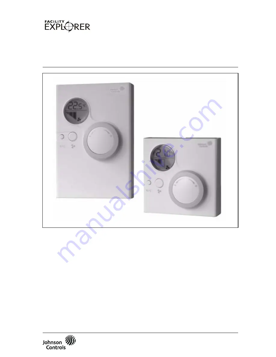
Страница 2: ... 80 3 15 120 4 72 25 0 98 6 Display in Celsius and Fahrenheit units 80 3 15 35 1 38 1 LCD Display with back light 2 Dial for Temperature Setpoint Adjustment 3 C F Button 4 Fan Button for fan speed adjustment 5 Service tool socket ...
Страница 3: ...II Figure 2 Removing the Cover from the Base ...
Страница 4: ...igure 3 Wall Mounting Base Dimensions mm in 31 1 22 60 2 36 2 x Ø 4 2 0 16 66 2 60 66 2 60 60 2 36 4 3 0 17 4 3 0 17 4 3 0 17 29 1 14 33 1 30 33 1 30 38 1 50 5 7 0 22 5 7 0 22 34 1 34 34 1 34 67 2 64 67 2 64 ...
Страница 5: ...IV Figure 4 Dual Switch DIP Switch Block Figure 5 Terminal Block Connection ...
Страница 6: ...V Figure 6 Service Port 4 pin for LP NRM0xx 000C Series Figure 7 Port 6 pin Modular Jack for LP NRM5xx 000C and LP NRM6xx 000C Series ...
Страница 7: ...m the FX Controller or from an external power source and has a 4 pin service port Figure 6 The LP NRM5xx 000C and LP NRM6xx 000C Series NRMs require a 15 VDC power supply from the FX Controller or from an external power source and have a 6 pin Modular Jack service port Figure 6 North American Emissions Compliance United States This equipment has been tested and found to comply with the limits for ...
Страница 8: ...ic models see Ordering Codes 4 Fan button for fan speed adjustment feature available in specific models see Ordering Codes 5 Service port 6 Display in Celsius and Fahrenheit units Mounting The NRM mounts directly on a wall surface in the room you want to control Choose a location for the NRM while considering the following information Place the room module where the occupant can easily read the LC...
Страница 9: ... holes Drill the holes and insert the plastic plugs wall anchors into the holes 2 Mount the module base on the wall and secure with at least two screws For other mounting options see Ordering Codes and refer to the corresponding installation sheets Addressing Figure 4 Dual Switch DIP Switch Block NRM models which are not addressable have a fixed physical address of 191 For those models which are a...
Страница 10: ...M Room Command Module only as an operating control Where failure or malfunction of the NRM could lead to personal injury or property damage to the controlled equipment or other property additional precautions must be designed into the control system Incorporate and maintain other devices such as supervisory or alarm systems or safety or limit controls intended to warn of or protect against failure...
Страница 11: ...ge to the terminals as marked 15 24 VAC VDC and COM common for the LP NRM0xx 000C Series NRM 15 VDC and COM common for the LP NRM5xx 000C and LP NRM6xx 000C Series NRMs Service Port The service port is located on the lower edge of the module There are two different types of service ports depending on the NRM Series you are using 4 Pin Service Port See Figure 6 for service port wiring for LP NRM0xx...
Страница 12: ...002 000C Yes Yes No No No LP NRM003 000C Yes Yes Yes No No LP NRM511 000C MUI No No No No Yes LP NRM502 000C Yes Yes No No No LP NRM503 000C Yes Yes Yes No No Product Code Features Options Size mm inch Service Port Type LCD Display Temperature Adjust Dial Fan Speed Selector Button F C Addressable LP NRM511 000C 80 x 80 mm 3 15 x 3 15 in MUI No No No No Yes LP NRM552 000C Yes Yes No Yes No LP NRM55...
Страница 13: ... x 4 in wall box TM 9100 8900 Special Tool to open module Europe T 4000 119 Special Tool to open module North America LP KIT100 000C Programming Key FX Controller Type MUI NRM Configuration Limits FX06 One MUI and one NRM FX06 Rev A One MUI and one NRM FX07 One MUI and one NRM FX07 Rev A One MUI and one NRM FX14 One MUI and two NRMs1 FX14 Rev A One MUI and two NRMs1 FX14 Rev B One MUI and two NRMs...
Страница 14: ...rew terminals in base for 1 5 mm2 16 AWG max wires Recommended tightening torque 0 5 Nm Temperature Sensor RTD Platinum element PTC 1k ohm at 0 C 32 F Pt1000 Class A DIN EN 60751 Suitable for residential and commercial office environments only Display and Controls LCD display with three digits and seven symbols Dial and push button s Communications Interface N2 Open Protocol communication Service ...
Страница 15: ...2 and higher FXVMA all versions Compliance Europe CE Mark Johnson Controls Inc declares that the Network Room Modules NRMs are in compliance with the essential requirements and other relevant provisions of the EMC Directive 2004 108 EC Canada UL Listed PAZX7 C22 2 No 205 Signal Equipment Industry Canada ICES 003 United States UL Listed PAZX UL 916 Energy Management Equipment FCC compliant to CFR 4...
Страница 16: ...10 Network Room Modules Installation Guide ...
Страница 17: ... Efficiency 507 E Michigan Street Milwaukee WI 53202 Johnson Controls is a registered trademark of Johnson Controls Inc All other marks herein are the marks of their respective owners 2010 Johnson Controls Inc ...