Installing a CAB3/CAB4 Cabinet
JWS-3 Embedded Installation
15
JWS-3 Installation and Operation Manual - P/N: 53550:Rev: A1 1/12/10
2.3 Installing a CAB3/CAB4 Cabinet
Install a new CAB-3/CAB-4 series cabinet according to the requirements of the local authority
having jurisdiction or prepare an existing CAB-3/CAB-4 series cabinet that houses a supported
Johnson Controls panel or annunciator. Refer to
Appendix A, “JWS-3 Compatible Node Types”, on
for list of supported panels and annunciators.
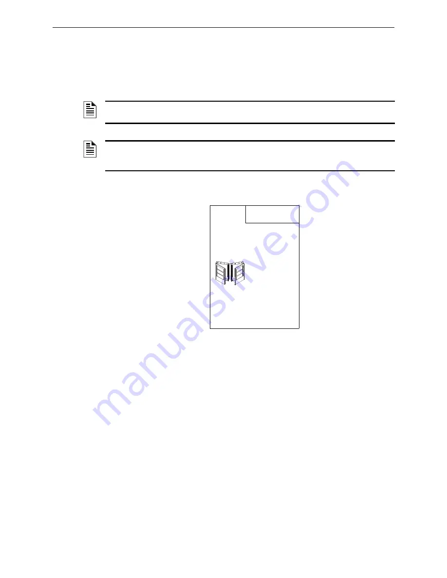
Figure 2.2 CAB-3/CAB-4 Series Installation Document, 15330
NOTE:
The CAB3/CAB4 cabinet is ordered separately. For installation details, refer to the CAB-3/
CAB-4 Series Installation Document, 15330 and or the panel’s or annunciator’s documentation.
NOTE:
Knockouts are provided on the unit so that the field wiring may be run in conduit if
required by the local authority having jurisdiction. All field wiring connections are intended to be
made at the installation wiring terminals provided as part of the unit.
CAB-3/CAB-4 Series Cabinets
Product Installation Document
PN 15330:I 10/23/07 07-695
1 General
All cabinets are fabricated from 16 gauge steel. The cabinet consists of two basic components: a backbox and a locking
door.
The key-locked door is provided with a pin-type hinge, two keys, and the necessary hardware to mount the door to the
backbox. The backbox has been engineered to provide ease-of-entry for the installer. Knockouts are positioned at
numerous points to let the installer bring conduit into the enclosure easily. Doors can be mounted on the left or right-hand
side. The same hinge works in both configurations, so that this choice can be made in the field. The door opens 180°.
Cabinets are available in five sizes: A through D, and AA. The outside dimensions are noted on each enclosure diagram.
“A” size accommodates one chassis, a power supply, and two 26 AH batteries; “D” size accommodates four chassis, a
power supply, and two 26 AH batteries; “AA” size holds one chassis with no compartment for batteries. A trim ring
option is available for semi-flush mounting. The CAB-3/CAB-4 Series is compatible with multiple chassis including the
CHS-M2, CHS2-M2, CHS-M3, CHS-4, CHS-4L, CHS-4N, CHS-BH, CHS-PS, CA-1, and CA-2. Note: CAB-4 series
backboxes and doors are sold separately.
2 Before You Begin
The option of mounting doors in either a left/right hand configuration
will aid in installation and service when two control panels are
mounted in a confined area or side by side (as shown). In this manner
the doors can be opened “barn door” style, permitting an open work
space. Note that in this type of installation it is necessary to leave
enough space between cabinets to insert a key into the locks on the
door frames.
IMPORTANT
:
Attach the two hinges and two alignment tabs to the
backbox
before
any equipment is installed. With chassis installed,
space is very limited.
Display Interface Assembly Note
: When the door is left-hand
mounted, the Display Interface Assembly (DIA) dress panel cannot be
opened when the door is at less than a 120° angle to the cabinet. If you are using the left-hand mounting option, be sure
that the door can open at least 120°. This is especially important if the cabinet is to be mounted in a closed area, such as a
closet or utility room.
3 Door Assembly Instructions
Hinges can be either left or right hand mounted. The illustrations and text depict a left hand mounted example. For a right
hand mounting, simply substitute right for left in the instructions.
1.
Insert door hinges (A) into the top and bottom slots of the side to be hinged (in this case the LEFT side). Secure the
hinges to the studs in the backbox with the #8 hex nuts provided. Note that the small hole on the outer tab faces
outward.
2.
Thread stud (B) into the BOTTOM hinge first. Thread from the bottom up. Place the grounding “star” washer on the
stud. Place the door's lower corner onto this stud. Placing the door on the lower stud first provides a place for the door
to rest while you complete the assembly.
3.
Align the door on the backbox, so that the door sits directly under the top hinge. Thread remaining stud (B) into the
TOP hinge and through the hole in the top of the door. Your door should now swing freely.
CA
B d
o
o
r
LH
.w
m
f
CA
B d
o
o
r RH.wmf
Содержание JWS-3
Страница 1: ...JWS 3 Installation and Operation Manual Document 53550 1 12 10 Rev A1 P N 53550 A1 ECN 10 018...
Страница 12: ...JWS 3 Features System Architecture 12 JWS 3 Installation and Operation Manual P N 53550 Rev A1 1 12 10...
Страница 46: ...JWS 3 Operation Administration Tab 46 JWS 3 Installation and Operation Manual P N 53550 Rev A1 1 12 10...


