SECTION 5 - BASIC HYDRAULIC INFORMATION & SCHEMATICS
3121200
5-5
Disassembly
DO NOT AT TEMPT TO SERVICE A HYDRAULIC C YLINDER WHILE IT IS
INSTALLED. THE CYLINDER MUST BE REMOVED FROM THE MACHINE AND ALL
PRESSURE MUST BE RELIEVED. AIR MUST NOT BE USED TO EXTEND OR
RETRACT THE CYLINDER. SAFETY GLASSES MUST BE WORN AT ALL TIMES BY
SERVICE PERSONNEL.
1.
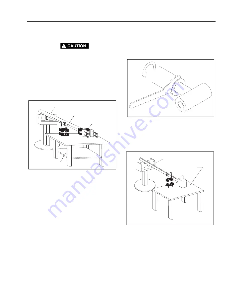
The cylinder should be secured in such a way as to pre-
vent rotation of the barrel while unscrewing the head
gland. Care should be taken to avoid damaging the rod
surface and to avoid excessive deformation of the barrel,
which could permanently damage the unit. Make sure
to support the rod during removal.
2.
Remove all dirt, grease, and other contaminants from
around the ports and the head gland. Drain all oil from
the unit. Extending and retracting the rod manually can
help purge the bulk of the remaining oil.
3.
Mark the orientation of the rod, gland, and barrel with a
permanent marker or paint pen. Do not apply any paint
on the chromed surface of the rod. Unscrew the head
gland from the cylinder assembly using a spanner
wrench in the holes provided in the OD of the head
gland.
NOTE:
The threads are locked with a non-permanent thread
adhesive during assembly. A quick tug on the wrench may
be necessary to release the thread adhesive.
4.
Remove the rod assembly from the barrel using care not
to damage the threads or any other component surface.
5.
Clamp the rod mount and support the rod assembly
with the chrome surface protected. Remove the piston
assembly either by unthreading the locknut with a
socket wrench or the piston itself from the rod using a
spanner wrench depending on the cylinder model.
ROD SUPPORT
PROTECTED ROD CLAMP
BARREL CLAMP
SUPPORT TABLE
SUPPORT TABLE
Figure 5-3. Cylinder Barrel Support
Figure 5-4. Cylinder Head Removal
MAE29480
SUPPORT TABLE
ROD SUPPORT
Figure 5-5. Cylinder Rod Support
Содержание T500J
Страница 1: ...Service and Maintenance Manual Model T500J PN 3121200 July 25 2018 Rev I AS NZS...
Страница 2: ......
Страница 16: ...xii 3121200 LIST OF TABLES TABLE NO TITLE PAGE NO This page left blank intentionally...
Страница 36: ...SECTION 2 GENERAL 2 8 3121200 NOTES...
Страница 115: ...SECTION 3 CHASSIS TURNTABLE 3121200 3 79 MAE29600 DRIVE MOTOR SPINDLE 1 Figure 3 37 Wheel Drive Removal and Installation...
Страница 136: ...SECTION 3 CHASSIS TURNTABLE 3 100 3121200 Figure 3 41 Battery Cable Routing Prior to SN 0030001804...
Страница 143: ...SECTION 3 CHASSIS TURNTABLE 3121200 3 107 Figure 3 45 Battery Charger Schematic...
Страница 213: ...SECTION 5 BASIC HYDRAULIC INFORMATION SCHEMATICS 3121200 5 39 This page left blank intentionally...
Страница 234: ...SECTION 5 BASIC HYDRAULIC INFORMATION SCHEMATICS 5 60 3121200 NOTES...
Страница 246: ...SECTION 6 JLG CONTROL SYSTEM 6 12 3121200 Figure 6 5 System Test Flow Chart Platform Tests...
Страница 248: ...SECTION 6 JLG CONTROL SYSTEM 6 14 3121200 Figure 6 6 System Test Flow Chart Ground Station Tests...
Страница 283: ...SECTION 7 BASIC ELECTRICAL INFORMATION SCHEMATICS 3121200 7 11 Figure 7 17 Connector Installation...
Страница 297: ...SECTION 7 BASIC ELECTRICAL INFORMATION SCHEMATICS 3121200 7 25 This page left blank intentionally...
Страница 304: ...SECTION 7 BASIC ELECTRICAL INFORMATION SCHEMATICS 7 32 3121200 NOTES...
Страница 305: ......


