SECTION 3 - CHASSIS & TURNTABLE
3-96
3121200
3.24
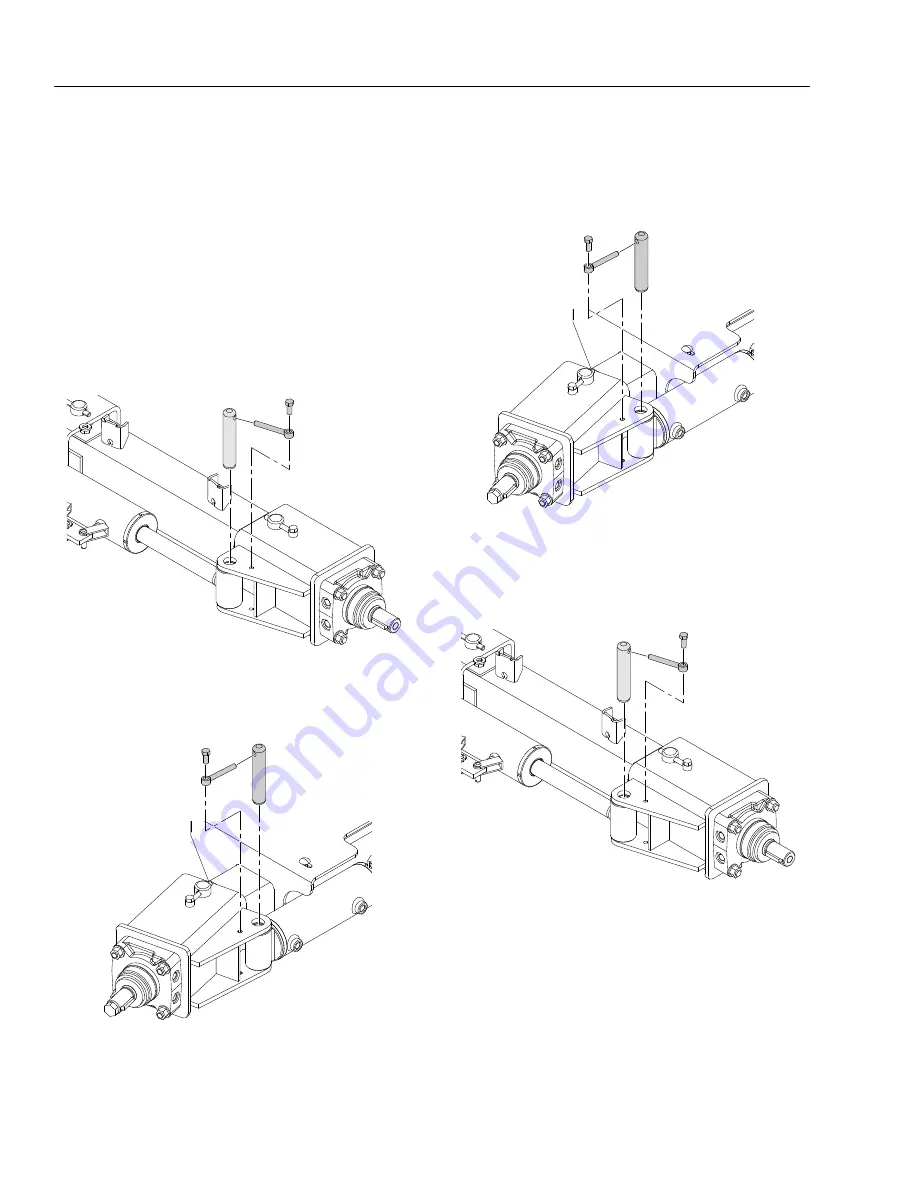
DRIVE ENGAGE CYLINDER
Removal
1.
Tag and disconnect the hoses running to the drive
engage
cylinder. Cap or plug all openings.
2.
Using an adequate supporting device, support the drive
engage cylinder so it doesn’t fall when the pin is
removed.
NOTE:
The drive engage cylinder weighs approximately 26 lbs.
(12 kg).
3.
Remove the retaining pins and pivot pin from the rod
end of the cylinder.
4.
Remove the retaining pins and pivot pin from the barrel
end of the cylinder and remove the cylinder from the
machine.
Installation
1.
Using suitable lifting device, lift the drive engage cylin-
der into position and install the pivot pin and retaining
pin into the barrel end of the cylinder.
NOTE:
The drive engage cylinder weighs approximately 26 lbs.
(12 kg).
2.
Install the pivot pin and retaining pin into the rod end of
the cylinder.
3.
Connect the hydraulic hoses to the drive engage cylin-
der as tagged during removal.
4.
Cycle the drive engage cylinder several times to check
for proper operation and any leakage.
MAE29610
MAE30670
MAE30670
MAE29610
Содержание T500J
Страница 1: ...Service and Maintenance Manual Model T500J PN 3121200 July 25 2018 Rev I AS NZS...
Страница 2: ......
Страница 16: ...xii 3121200 LIST OF TABLES TABLE NO TITLE PAGE NO This page left blank intentionally...
Страница 36: ...SECTION 2 GENERAL 2 8 3121200 NOTES...
Страница 115: ...SECTION 3 CHASSIS TURNTABLE 3121200 3 79 MAE29600 DRIVE MOTOR SPINDLE 1 Figure 3 37 Wheel Drive Removal and Installation...
Страница 136: ...SECTION 3 CHASSIS TURNTABLE 3 100 3121200 Figure 3 41 Battery Cable Routing Prior to SN 0030001804...
Страница 143: ...SECTION 3 CHASSIS TURNTABLE 3121200 3 107 Figure 3 45 Battery Charger Schematic...
Страница 213: ...SECTION 5 BASIC HYDRAULIC INFORMATION SCHEMATICS 3121200 5 39 This page left blank intentionally...
Страница 234: ...SECTION 5 BASIC HYDRAULIC INFORMATION SCHEMATICS 5 60 3121200 NOTES...
Страница 246: ...SECTION 6 JLG CONTROL SYSTEM 6 12 3121200 Figure 6 5 System Test Flow Chart Platform Tests...
Страница 248: ...SECTION 6 JLG CONTROL SYSTEM 6 14 3121200 Figure 6 6 System Test Flow Chart Ground Station Tests...
Страница 283: ...SECTION 7 BASIC ELECTRICAL INFORMATION SCHEMATICS 3121200 7 11 Figure 7 17 Connector Installation...
Страница 297: ...SECTION 7 BASIC ELECTRICAL INFORMATION SCHEMATICS 3121200 7 25 This page left blank intentionally...
Страница 304: ...SECTION 7 BASIC ELECTRICAL INFORMATION SCHEMATICS 7 32 3121200 NOTES...
Страница 305: ......


