


SECTION 6 - JLG CONTROL SYSTE
M
3121160
6-51
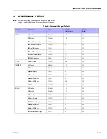
6.3
MACHINE ORIENTATION WHEN DOING SPEED
TESTS
Tower Lift:
Upper Boom horizontal, telescoped in. Tower lift
up, record time. Tower lift down, record time.
Lift:
Tower lift fully elevated, tower telescope fully extended,
main telescope fully retracted.
Swing:
Boom at full elevation, telescope retracted. Swing the
turntable off center and stop. Swing the opposite direction
and start the test when the turntable is centered up. This elim-
inates ramp up and down on the controller affecting times.
Telescope:
Boom at full elevation, telescope retracted. Tele-
scope out, record time. Telescope in, record time.
Drive:
Test should be done on a smooth, level surface. Drive
select switch should be set at high speed. Start approximately
25 feet from starting point so that the unit is at maximum
speed when starting the test. Results should be recorded for a
200 foot course. Drive forward, record time. Drive reverse,
record time.
Drive (Above Horizontal):
Test should be done on a smooth,
level surface. Drive select switch should be set at low engine,
low drive. The platform speed control knob should be selected
to the creep speed. This simulates machine speed when the
boom is above horizontal. Results should be recorded for a 50
foot course. Drive forward, record time. Drive in reverse, record
time.
Platform Rotate:
Platform level and completely rotated one
direction. Rotate the opposite direction, record time. Rotate
the other direction, record time.
Articulating Jib
: Platform level and centered with the boom.
Start with jib down. Jib up, record time. Jib down, record time.
Test Notes
1.
Stop watch should be started with the function, not
with the controller or switch.
2.
Drive test results reflect (15 X 19.5 OR 18 X 19.5). Tires on
740AJ is, air or foam filled.
3.
All speed tests are run from the platform. These speeds
do not reflect ground control operation.
4.
The platform speed control knob must be at full speed
(turned clockwise completely).
5.
Function speeds may vary due to cold thick hydraulic oil.
Tests should be run with the oil temperature above 100°
F (38° C).
6.
Some flow control functions may not work with the
speed knob clicked into the creep position.
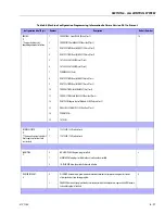
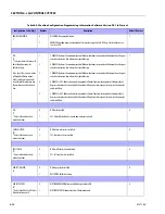
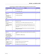
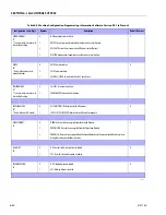
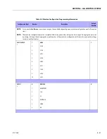
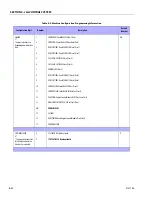
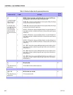
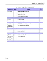
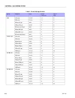
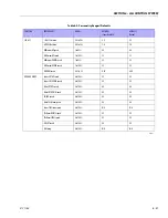
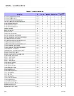
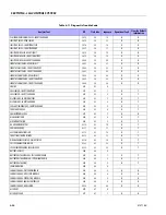
Table 6-7. Function Speeds (In Seconds)
Function
740AJ
Speed Tolerances
(Seconds)
Main Lift Up
45-50
Main Lift Down
45-50
Swing Right & Left
NOTE:
Max 10% Difference Between
Left & Right
79-101
Platform Rotate Left & Right
NOTE:
Max 15% Difference Between
Left & Right
19-30
Jib Up
20-30
Jib Down
30-40
Tower Lift Up
57-70
Tower Lift Down
44-53
Drive (2-WD)
Forward & Reverse
33-45
Drive (4-WD)
Forward & Reverse
33-45
Drive (2 & 4-WD) Horizontal
Above elevation forward & reverse (CE)
122 MIN
Drive (2WD) Horizontal above elevation
Forward & reverse (ANSI)
61-70
Drive (4WD) Horizontal above elevation
Forward & reverse (ANSI)
122 MIN
4150241 H
Содержание 740AJ
Страница 1: ...Service and Maintenance Manual Model 740AJ Prior to S N 0300185827 P N 3121160 October 24 2017 AS NZS...
Страница 2: ......
Страница 51: ...SECTION 2 GENERAL 3121160 2 11 Figure 2 2 Engine Operating Temperature Specifications Ford 4150548 E...
Страница 55: ...SECTION 3 CHASSIS TURNTABLE 3121160 3 3 This page left blank intentionally...
Страница 56: ...SECTION 3 CHASSIS TURNTABLE 3 4 3121160 1 Figure 3 2 Axle and Steering Installation Sheet 1 of 2 0258286 C...
Страница 100: ...SECTION 3 CHASSIS TURNTABLE 3 48 3121160 Figure 3 37 Swing Bearing Tolerance Boom Placement Sheet 1 of 2...
Страница 101: ...SECTION 3 CHASSIS TURNTABLE 3121160 3 49 Figure 3 38 Swing Bearing Tolerance Boom Placement Sheet 2 of 2...
Страница 116: ...SECTION 3 CHASSIS TURNTABLE 3 64 3121160 Figure 3 44 Swing Hub Prior to SN 0300074383...
Страница 124: ...SECTION 3 CHASSIS TURNTABLE 3 72 3121160 Figure 3 45 Swing Drive Hub Fairfield SN 0300074383 through 0300134352...
Страница 180: ...SECTION 3 CHASSIS TURNTABLE 3 128 3121160 1 Figure 3 66 Auxiliary Pump Location 1 AuxiliaryPump 2 HydraulicTank...
Страница 203: ...SECTION 3 CHASSIS TURNTABLE 3121160 3 151 Figure 3 77 EFI Component Location...
Страница 206: ...SECTION 3 CHASSIS TURNTABLE 3 154 3121160 Figure 3 78 ECM EPM Identification ECM EPM...
Страница 213: ...SECTION 3 CHASSIS TURNTABLE 3121160 3 161 Megajector Regulator LockoffSolenoid Figure 3 80 LPG System Components Mixer...
Страница 219: ...SECTION 3 CHASSIS TURNTABLE 3121160 3 167 Figure 3 81 Check Out and Initial Start Up Procedures...
Страница 224: ...SECTION 3 CHASSIS TURNTABLE 3 172 3121160 Figure 3 83 Deutz EMR 2 Troubleshooting Flow Chart...
Страница 225: ...SECTION 3 CHASSIS TURNTABLE 3121160 3 173 Figure 3 84 Deutz EMR 2 Vehicle Side Connection Diagram...
Страница 226: ...SECTION 3 CHASSIS TURNTABLE 3 174 3121160 Figure 3 85 Deutz EMR 2 Engine Side Connection Diagram Sheet 1 of 2...
Страница 227: ...SECTION 3 CHASSIS TURNTABLE 3121160 3 175 Figure 3 86 Deutz EMR 2 Engine Side Connection Diagram Sheet 2 of 2...
Страница 228: ...SECTION 3 CHASSIS TURNTABLE 3 176 3121160 Figure 3 87 EMR 2 Engine Plug Pin Identification...
Страница 229: ...SECTION 3 CHASSIS TURNTABLE 3121160 3 177 Figure 3 88 EMR 2 Vehicle Plug Pin Identification...
Страница 230: ...SECTION 3 CHASSIS TURNTABLE 3 178 3121160 Figure 3 89 EMR2 Fault Codes Sheet 1 of 5...
Страница 231: ...SECTION 3 CHASSIS TURNTABLE 3121160 3 179 Figure 3 90 EMR2 Fault Codes Sheet 2 of 5...
Страница 232: ...SECTION 3 CHASSIS TURNTABLE 3 180 3121160 Figure 3 91 EMR2 Fault Codes Sheet 3 of 5...
Страница 233: ...SECTION 3 CHASSIS TURNTABLE 3121160 3 181 Figure 3 92 EMR2 Fault Codes Sheet 4 of 5...
Страница 234: ...SECTION 3 CHASSIS TURNTABLE 3 182 3121160 Figure 3 93 EMR2 Fault Codes Sheet 5 of 5...
Страница 303: ...SECTION 4 BOOM PLATFORM 3121160 4 31 Figure 4 20 Rotator Assembly HELAC...
Страница 335: ...SECTION 4 BOOM PLATFORM 3121160 4 63 THIS SENSOR ON NON ADE MACHINES ONLY Figure 4 27 UMS Sensor Location...
Страница 336: ...SECTION 4 BOOM PLATFORM 4 64 3121160 Figure 4 28 UMS Module Location ADE MACHINES NON ADE MACHINES...
Страница 425: ...SECTION 5 BASIC HYDRAULIC INFORMATION AND SCHEMATICS 3121160 5 81 Figure 5 131 Variable Displacement Pump Rexroth...
Страница 443: ...SECTION 5 BASIC HYDRAULIC INFORMATION AND SCHEMATICS 3121160 5 99 Figure 5 146 Fault Logic Troubleshooting...
Страница 444: ...SECTION 5 BASIC HYDRAULIC INFORMATION AND SCHEMATICS 5 100 3121160 Figure 5 147 Fault Logic Troubleshooting...
Страница 445: ...SECTION 5 BASIC HYDRAULIC INFORMATION AND SCHEMATICS 3121160 5 101 Figure 5 148 Fault Logic Troubleshooting...
Страница 460: ...SECTION 5 BASIC HYDRAULIC INFORMATION AND SCHEMATICS 5 116 3121160 NOTES...
Страница 467: ...SECTION 6 JLG CONTROL SYSTEM 3121160 6 7 Figure 6 2 ADE Block Diagram...
Страница 471: ...SECTION 6 JLG CONTROL SYSTEM 3121160 6 11 Figure 6 6 Analyzer Flow Chart Prior to Version 5 X Software Sheet 4 of 4...
Страница 473: ...SECTION 6 JLG CONTROL SYSTEM 3121160 6 13 Figure 6 8 Analyzer Flow Chart Version 5 X Software Sheet 2 of 4...
Страница 534: ...SECTION 6 JLG CONTROL SYSTEM 6 74 3121160 NOTES...
Страница 545: ...SECTION 7 BASIC ELECTRICAL INFORMATION SCHEMATICS 3121160 7 11 Figure 7 15 Connector Installation...
Страница 580: ...SECTION 7 BASIC ELECTRICAL INFORMATION SCHEMATICS 7 46 3121160 NOTES...
Страница 581: ......


