


SECTION 5 - BASIC HYDRAULIC INFOR
M
ATION AND SCHE
M
ATICS
5-60
3121160
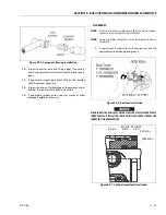
5.7
CYLINDER REMOVAL AND INSTALLATION
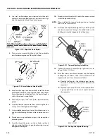
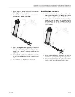
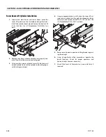
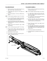
Main Boom Telescope Cylinder Removal
1.
Place machine on a flat and level surface, with main
boom in the horizontal position.
2.
Extend the boom to gain access to main fly boom tele-
scope cylinder rod end pin.
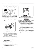
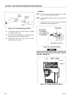
3.
Remove the hardware securing the telescope cylinder
rod attach pin to the boom. Using a suitable brass drift,
drive out the cylinder rod attach pin.
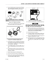
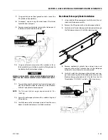
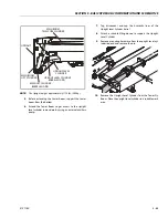
NOTE:
The Main Boom weighs approximately 2226 lbs. (1010 kg).
4.
Using a suitable sling and lifting device, secure the plat-
form end of the boom.
5.
Place blocking under the main lift cylinder to prevent it
from falling when the attaching hardware is removed.
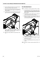
6.
Remove the hardware securing the main lift cylinder rod
attach pin to the boom. Using a suitable brass drift, drive
out the cylinder rod attach pin.
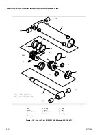
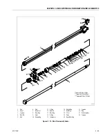
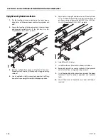
Figure 5-125. Components Main Boom and Tower Boom
Содержание 740AJ
Страница 1: ...Service and Maintenance Manual Model 740AJ Prior to S N 0300185827 P N 3121160 October 24 2017 AS NZS...
Страница 2: ......
Страница 51: ...SECTION 2 GENERAL 3121160 2 11 Figure 2 2 Engine Operating Temperature Specifications Ford 4150548 E...
Страница 55: ...SECTION 3 CHASSIS TURNTABLE 3121160 3 3 This page left blank intentionally...
Страница 56: ...SECTION 3 CHASSIS TURNTABLE 3 4 3121160 1 Figure 3 2 Axle and Steering Installation Sheet 1 of 2 0258286 C...
Страница 100: ...SECTION 3 CHASSIS TURNTABLE 3 48 3121160 Figure 3 37 Swing Bearing Tolerance Boom Placement Sheet 1 of 2...
Страница 101: ...SECTION 3 CHASSIS TURNTABLE 3121160 3 49 Figure 3 38 Swing Bearing Tolerance Boom Placement Sheet 2 of 2...
Страница 116: ...SECTION 3 CHASSIS TURNTABLE 3 64 3121160 Figure 3 44 Swing Hub Prior to SN 0300074383...
Страница 124: ...SECTION 3 CHASSIS TURNTABLE 3 72 3121160 Figure 3 45 Swing Drive Hub Fairfield SN 0300074383 through 0300134352...
Страница 180: ...SECTION 3 CHASSIS TURNTABLE 3 128 3121160 1 Figure 3 66 Auxiliary Pump Location 1 AuxiliaryPump 2 HydraulicTank...
Страница 203: ...SECTION 3 CHASSIS TURNTABLE 3121160 3 151 Figure 3 77 EFI Component Location...
Страница 206: ...SECTION 3 CHASSIS TURNTABLE 3 154 3121160 Figure 3 78 ECM EPM Identification ECM EPM...
Страница 213: ...SECTION 3 CHASSIS TURNTABLE 3121160 3 161 Megajector Regulator LockoffSolenoid Figure 3 80 LPG System Components Mixer...
Страница 219: ...SECTION 3 CHASSIS TURNTABLE 3121160 3 167 Figure 3 81 Check Out and Initial Start Up Procedures...
Страница 224: ...SECTION 3 CHASSIS TURNTABLE 3 172 3121160 Figure 3 83 Deutz EMR 2 Troubleshooting Flow Chart...
Страница 225: ...SECTION 3 CHASSIS TURNTABLE 3121160 3 173 Figure 3 84 Deutz EMR 2 Vehicle Side Connection Diagram...
Страница 226: ...SECTION 3 CHASSIS TURNTABLE 3 174 3121160 Figure 3 85 Deutz EMR 2 Engine Side Connection Diagram Sheet 1 of 2...
Страница 227: ...SECTION 3 CHASSIS TURNTABLE 3121160 3 175 Figure 3 86 Deutz EMR 2 Engine Side Connection Diagram Sheet 2 of 2...
Страница 228: ...SECTION 3 CHASSIS TURNTABLE 3 176 3121160 Figure 3 87 EMR 2 Engine Plug Pin Identification...
Страница 229: ...SECTION 3 CHASSIS TURNTABLE 3121160 3 177 Figure 3 88 EMR 2 Vehicle Plug Pin Identification...
Страница 230: ...SECTION 3 CHASSIS TURNTABLE 3 178 3121160 Figure 3 89 EMR2 Fault Codes Sheet 1 of 5...
Страница 231: ...SECTION 3 CHASSIS TURNTABLE 3121160 3 179 Figure 3 90 EMR2 Fault Codes Sheet 2 of 5...
Страница 232: ...SECTION 3 CHASSIS TURNTABLE 3 180 3121160 Figure 3 91 EMR2 Fault Codes Sheet 3 of 5...
Страница 233: ...SECTION 3 CHASSIS TURNTABLE 3121160 3 181 Figure 3 92 EMR2 Fault Codes Sheet 4 of 5...
Страница 234: ...SECTION 3 CHASSIS TURNTABLE 3 182 3121160 Figure 3 93 EMR2 Fault Codes Sheet 5 of 5...
Страница 303: ...SECTION 4 BOOM PLATFORM 3121160 4 31 Figure 4 20 Rotator Assembly HELAC...
Страница 335: ...SECTION 4 BOOM PLATFORM 3121160 4 63 THIS SENSOR ON NON ADE MACHINES ONLY Figure 4 27 UMS Sensor Location...
Страница 336: ...SECTION 4 BOOM PLATFORM 4 64 3121160 Figure 4 28 UMS Module Location ADE MACHINES NON ADE MACHINES...
Страница 425: ...SECTION 5 BASIC HYDRAULIC INFORMATION AND SCHEMATICS 3121160 5 81 Figure 5 131 Variable Displacement Pump Rexroth...
Страница 443: ...SECTION 5 BASIC HYDRAULIC INFORMATION AND SCHEMATICS 3121160 5 99 Figure 5 146 Fault Logic Troubleshooting...
Страница 444: ...SECTION 5 BASIC HYDRAULIC INFORMATION AND SCHEMATICS 5 100 3121160 Figure 5 147 Fault Logic Troubleshooting...
Страница 445: ...SECTION 5 BASIC HYDRAULIC INFORMATION AND SCHEMATICS 3121160 5 101 Figure 5 148 Fault Logic Troubleshooting...
Страница 460: ...SECTION 5 BASIC HYDRAULIC INFORMATION AND SCHEMATICS 5 116 3121160 NOTES...
Страница 467: ...SECTION 6 JLG CONTROL SYSTEM 3121160 6 7 Figure 6 2 ADE Block Diagram...
Страница 471: ...SECTION 6 JLG CONTROL SYSTEM 3121160 6 11 Figure 6 6 Analyzer Flow Chart Prior to Version 5 X Software Sheet 4 of 4...
Страница 473: ...SECTION 6 JLG CONTROL SYSTEM 3121160 6 13 Figure 6 8 Analyzer Flow Chart Version 5 X Software Sheet 2 of 4...
Страница 534: ...SECTION 6 JLG CONTROL SYSTEM 6 74 3121160 NOTES...
Страница 545: ...SECTION 7 BASIC ELECTRICAL INFORMATION SCHEMATICS 3121160 7 11 Figure 7 15 Connector Installation...
Страница 580: ...SECTION 7 BASIC ELECTRICAL INFORMATION SCHEMATICS 7 46 3121160 NOTES...
Страница 581: ......


