


SECTION
4
- BOO
M
& PLATFOR
M
4-66
3121160
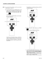
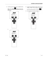
4.18 UMS TROUBLESHOOTING AND FAULT MESSAGES
NON-ADE MACHINES
Tower Lift Down Permanently closed
2/2 FUNCTION LOCKED OUT - TOWER LIFT DOWN PERMANENTLY
CLOSED.
The control system shall illuminate lamps and sound the alarm at
startup for one second on and one second off. If the control sys-
tem detects the TOWER LIFT DOWN, it shall report a fault. The
TOWER LIFT DOWN function shall be locked out and activate the
ground boom malfunction indicator lamp, upright tilted lamp
and platform alarm continually until the condition is cleared.
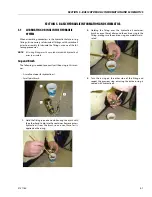
Solution:
• Inspect switch and harness. Voltage (
12V) should only be
present on J1-3 of the UMS module when Tower Down
switch is closed.
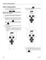
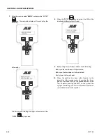
Backward Stability Concern Message
2/5 UMS SENSOR BACKWARD LIMIT REACHED.
When the upright angle relative to the turntable is higher than
+2.5° (away from the work platform), tower lift down shall be dis-
allowed immediately. Tower Lift Down shall be re-allowed when
the upright angle relative to the turntable is less than 2.0
. If
Tower Lift Down is disabled for more than 1.5 seconds, the
ground boom malfunction indicator lamp, upright tilted lamp
and platform alarm shall light/sound continually and a fault shall
be raised. These conditions shall be latched along with Tower Lift
Down until the upright angle is less than 2.0
for 2 seconds and
the Tower Lift Down command is returned to neutral.
Solution:
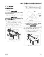
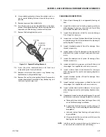
• Inspect sensor mounting.
• Verify sensor calibration on level pad.
• Follow the corrective action listed on decal 1702265
located near the red knob of the machine.
• Inspect machine hydraulics.
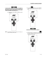
Forward Stability Concern Message
2/5 UMS SENSOR FORWARD LIMIT REACHED.
When the upright angle relative to the turntable is less than –4.0°
for longer than 1.5 seconds, the ground boom malfunction indi-
cator lamp, the platform distress lamp, and platform alarm shall
light/sound continually and a fault shall be raised. The light/
alarm signal shall be removed only when the upright angle
reaches values greater than –3.0° for 2 seconds.
Solution:
• Inspect sensor mounting.
• Verify sensor calibration on level pad.
• Tower lift down.
• Inspect machine hydraulics.
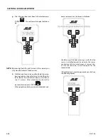
UMS Out of Usable Range Message
2/5 UMS SENSOR OUT OF USABLE RANGE
When both the Turntable tilt sensor and the UMS sensor read
greater then
10
in the same direction the UMS shall be disen-
gaged until the condition no longer exists and a fault shall be
raised.
Solution:
• Verify the message clears when operating the machine on
grade less than 10
.
• Inspect sensor mounting.
• Verify sensor calibration on level pad.
Battery Voltage < 9.0 Volts
4/4 SYSTEM VOLTS LOW
Battery voltage is below 9V.
Solution:
• Inspect battery and alternator output.
• Inspect harness, looking closely for possible short circuits.
Battery Voltage > 16.0 Volts
4/4 SYSTEM VOLTS HIGH
Battery voltage is above 16V.
Solution:
• Inspect battery and alternator output.
Содержание 740AJ
Страница 1: ...Service and Maintenance Manual Model 740AJ Prior to S N 0300185827 P N 3121160 October 24 2017 AS NZS...
Страница 2: ......
Страница 51: ...SECTION 2 GENERAL 3121160 2 11 Figure 2 2 Engine Operating Temperature Specifications Ford 4150548 E...
Страница 55: ...SECTION 3 CHASSIS TURNTABLE 3121160 3 3 This page left blank intentionally...
Страница 56: ...SECTION 3 CHASSIS TURNTABLE 3 4 3121160 1 Figure 3 2 Axle and Steering Installation Sheet 1 of 2 0258286 C...
Страница 100: ...SECTION 3 CHASSIS TURNTABLE 3 48 3121160 Figure 3 37 Swing Bearing Tolerance Boom Placement Sheet 1 of 2...
Страница 101: ...SECTION 3 CHASSIS TURNTABLE 3121160 3 49 Figure 3 38 Swing Bearing Tolerance Boom Placement Sheet 2 of 2...
Страница 116: ...SECTION 3 CHASSIS TURNTABLE 3 64 3121160 Figure 3 44 Swing Hub Prior to SN 0300074383...
Страница 124: ...SECTION 3 CHASSIS TURNTABLE 3 72 3121160 Figure 3 45 Swing Drive Hub Fairfield SN 0300074383 through 0300134352...
Страница 180: ...SECTION 3 CHASSIS TURNTABLE 3 128 3121160 1 Figure 3 66 Auxiliary Pump Location 1 AuxiliaryPump 2 HydraulicTank...
Страница 203: ...SECTION 3 CHASSIS TURNTABLE 3121160 3 151 Figure 3 77 EFI Component Location...
Страница 206: ...SECTION 3 CHASSIS TURNTABLE 3 154 3121160 Figure 3 78 ECM EPM Identification ECM EPM...
Страница 213: ...SECTION 3 CHASSIS TURNTABLE 3121160 3 161 Megajector Regulator LockoffSolenoid Figure 3 80 LPG System Components Mixer...
Страница 219: ...SECTION 3 CHASSIS TURNTABLE 3121160 3 167 Figure 3 81 Check Out and Initial Start Up Procedures...
Страница 224: ...SECTION 3 CHASSIS TURNTABLE 3 172 3121160 Figure 3 83 Deutz EMR 2 Troubleshooting Flow Chart...
Страница 225: ...SECTION 3 CHASSIS TURNTABLE 3121160 3 173 Figure 3 84 Deutz EMR 2 Vehicle Side Connection Diagram...
Страница 226: ...SECTION 3 CHASSIS TURNTABLE 3 174 3121160 Figure 3 85 Deutz EMR 2 Engine Side Connection Diagram Sheet 1 of 2...
Страница 227: ...SECTION 3 CHASSIS TURNTABLE 3121160 3 175 Figure 3 86 Deutz EMR 2 Engine Side Connection Diagram Sheet 2 of 2...
Страница 228: ...SECTION 3 CHASSIS TURNTABLE 3 176 3121160 Figure 3 87 EMR 2 Engine Plug Pin Identification...
Страница 229: ...SECTION 3 CHASSIS TURNTABLE 3121160 3 177 Figure 3 88 EMR 2 Vehicle Plug Pin Identification...
Страница 230: ...SECTION 3 CHASSIS TURNTABLE 3 178 3121160 Figure 3 89 EMR2 Fault Codes Sheet 1 of 5...
Страница 231: ...SECTION 3 CHASSIS TURNTABLE 3121160 3 179 Figure 3 90 EMR2 Fault Codes Sheet 2 of 5...
Страница 232: ...SECTION 3 CHASSIS TURNTABLE 3 180 3121160 Figure 3 91 EMR2 Fault Codes Sheet 3 of 5...
Страница 233: ...SECTION 3 CHASSIS TURNTABLE 3121160 3 181 Figure 3 92 EMR2 Fault Codes Sheet 4 of 5...
Страница 234: ...SECTION 3 CHASSIS TURNTABLE 3 182 3121160 Figure 3 93 EMR2 Fault Codes Sheet 5 of 5...
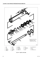
Страница 303: ...SECTION 4 BOOM PLATFORM 3121160 4 31 Figure 4 20 Rotator Assembly HELAC...
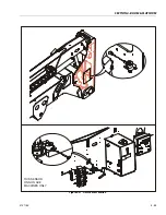
Страница 335: ...SECTION 4 BOOM PLATFORM 3121160 4 63 THIS SENSOR ON NON ADE MACHINES ONLY Figure 4 27 UMS Sensor Location...
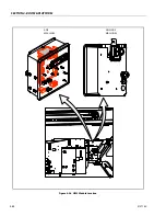
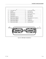
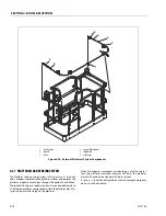
Страница 336: ...SECTION 4 BOOM PLATFORM 4 64 3121160 Figure 4 28 UMS Module Location ADE MACHINES NON ADE MACHINES...
Страница 425: ...SECTION 5 BASIC HYDRAULIC INFORMATION AND SCHEMATICS 3121160 5 81 Figure 5 131 Variable Displacement Pump Rexroth...
Страница 443: ...SECTION 5 BASIC HYDRAULIC INFORMATION AND SCHEMATICS 3121160 5 99 Figure 5 146 Fault Logic Troubleshooting...
Страница 444: ...SECTION 5 BASIC HYDRAULIC INFORMATION AND SCHEMATICS 5 100 3121160 Figure 5 147 Fault Logic Troubleshooting...
Страница 445: ...SECTION 5 BASIC HYDRAULIC INFORMATION AND SCHEMATICS 3121160 5 101 Figure 5 148 Fault Logic Troubleshooting...
Страница 460: ...SECTION 5 BASIC HYDRAULIC INFORMATION AND SCHEMATICS 5 116 3121160 NOTES...
Страница 467: ...SECTION 6 JLG CONTROL SYSTEM 3121160 6 7 Figure 6 2 ADE Block Diagram...
Страница 471: ...SECTION 6 JLG CONTROL SYSTEM 3121160 6 11 Figure 6 6 Analyzer Flow Chart Prior to Version 5 X Software Sheet 4 of 4...
Страница 473: ...SECTION 6 JLG CONTROL SYSTEM 3121160 6 13 Figure 6 8 Analyzer Flow Chart Version 5 X Software Sheet 2 of 4...
Страница 534: ...SECTION 6 JLG CONTROL SYSTEM 6 74 3121160 NOTES...
Страница 545: ...SECTION 7 BASIC ELECTRICAL INFORMATION SCHEMATICS 3121160 7 11 Figure 7 15 Connector Installation...
Страница 580: ...SECTION 7 BASIC ELECTRICAL INFORMATION SCHEMATICS 7 46 3121160 NOTES...
Страница 581: ......


