SECTION
4
- BOO
M
& PLATFOR
M
3121160
4-45
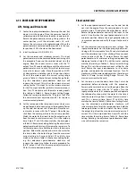
Testing the Actuator
If the equipment is available, the actuator should be tested on a
hydraulic test bench. The breakaway pressure — the pressure at
which the shaft begins to rotate — should be approximately 400
psi (28 bar). Cycle the actuator at least 25 times at 3000 psi (210
bar) pressure. After the 25 rotations, increase the pressure to
4500 psi (315 bar) to check for leaks and cracks. Perform the test
again at the end of the rotation in the opposite direction.
TESTING THE ACTUATOR FOR INTERNAL LEAKAGE
If the actuator is equipped with a counterbalance valve, plug the
valve ports. Connect the hydraulic lines to the housing ports.
Bleed all air from the actuator (see Installation and Bleeding)
Rotate the shaft to the end of rotation at 3000 psi (210 bar) and
maintain pressure. Remove the hydraulic line from the non-pres-
surized side.
Continuous oil flow from the open housing port indicates inter-
nal leakage across the piston. Replace the line and rotate the
shaft to the end of rotation in the opposite direction. Repeat the
test procedure outlined above for the other port. If there is an
internal leak, disassemble, inspect and repair.
Installation and Bleeding
After installation of the actuator on the equipment, it is impor-
tant that all safety devices such as tie rods or safety cables are
properly reattached.
To purge air from the hydraulic lines, connect them together to
create a closed loop and pump hydraulic fluid through them.
Review the hydraulic schematic to determine which hydraulic
lines to connect. The linear feet and inside diameter of the
hydraulic supply lines together with pump capacity will deter-
mine the amount of pumping time required to fully purge the
hydraulic system.
Bleeding may be necessary if excessive backlash is exhibited
after the actuator is connected to the hydraulic system. The fol-
lowing steps are recommended when a minimum of two gallons
(8 liters) is purged.
1.
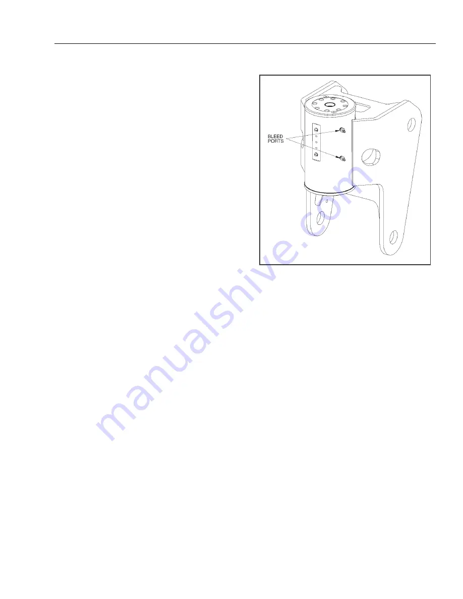
Connect a 3/16 in. inside diameter x 5/16 in. outside
diameter x 5 foot clear, vinyl drain tube to each of the
two bleed nipples. Secure them with hose clamps. Place
the vinyl tubes in a clean 5-gallon container to collect
the purged oil. The oil can be returned to the reservoir
after this procedure is completed.
2.
With an operator in the platform, open both bleed nip-
ples 1/4 turn. Hydraulically rotate the platform to the
end of rotation (either clockwise or counterclockwise),
and maintain hydraulic pressure. Oil with small air bub-
bles will be seen flowing through the tubes. Allow a 1/2
gallon of fluid to be purged from the actuator.
3.
Keep the fittings open and rotate the platform in the
opposite direction to the end position. Maintain hydrau-
lic pressure until an additional 1/4 gallon of fluid is
pumped into the container.
4.
Repeat steps 2 & 3. After the last 1/2 gallon is purged,
close both bleed nipples before rotating away from the
end position.
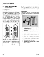
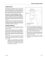
TYPICAL CONFIGURATION
OF ACTUATOR
Содержание 740AJ
Страница 1: ...Service and Maintenance Manual Model 740AJ Prior to S N 0300185827 P N 3121160 October 24 2017 AS NZS...
Страница 2: ......
Страница 51: ...SECTION 2 GENERAL 3121160 2 11 Figure 2 2 Engine Operating Temperature Specifications Ford 4150548 E...
Страница 55: ...SECTION 3 CHASSIS TURNTABLE 3121160 3 3 This page left blank intentionally...
Страница 56: ...SECTION 3 CHASSIS TURNTABLE 3 4 3121160 1 Figure 3 2 Axle and Steering Installation Sheet 1 of 2 0258286 C...
Страница 100: ...SECTION 3 CHASSIS TURNTABLE 3 48 3121160 Figure 3 37 Swing Bearing Tolerance Boom Placement Sheet 1 of 2...
Страница 101: ...SECTION 3 CHASSIS TURNTABLE 3121160 3 49 Figure 3 38 Swing Bearing Tolerance Boom Placement Sheet 2 of 2...
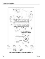
Страница 116: ...SECTION 3 CHASSIS TURNTABLE 3 64 3121160 Figure 3 44 Swing Hub Prior to SN 0300074383...
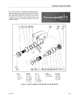
Страница 124: ...SECTION 3 CHASSIS TURNTABLE 3 72 3121160 Figure 3 45 Swing Drive Hub Fairfield SN 0300074383 through 0300134352...
Страница 180: ...SECTION 3 CHASSIS TURNTABLE 3 128 3121160 1 Figure 3 66 Auxiliary Pump Location 1 AuxiliaryPump 2 HydraulicTank...
Страница 203: ...SECTION 3 CHASSIS TURNTABLE 3121160 3 151 Figure 3 77 EFI Component Location...
Страница 206: ...SECTION 3 CHASSIS TURNTABLE 3 154 3121160 Figure 3 78 ECM EPM Identification ECM EPM...
Страница 213: ...SECTION 3 CHASSIS TURNTABLE 3121160 3 161 Megajector Regulator LockoffSolenoid Figure 3 80 LPG System Components Mixer...
Страница 219: ...SECTION 3 CHASSIS TURNTABLE 3121160 3 167 Figure 3 81 Check Out and Initial Start Up Procedures...
Страница 224: ...SECTION 3 CHASSIS TURNTABLE 3 172 3121160 Figure 3 83 Deutz EMR 2 Troubleshooting Flow Chart...
Страница 225: ...SECTION 3 CHASSIS TURNTABLE 3121160 3 173 Figure 3 84 Deutz EMR 2 Vehicle Side Connection Diagram...
Страница 226: ...SECTION 3 CHASSIS TURNTABLE 3 174 3121160 Figure 3 85 Deutz EMR 2 Engine Side Connection Diagram Sheet 1 of 2...
Страница 227: ...SECTION 3 CHASSIS TURNTABLE 3121160 3 175 Figure 3 86 Deutz EMR 2 Engine Side Connection Diagram Sheet 2 of 2...
Страница 228: ...SECTION 3 CHASSIS TURNTABLE 3 176 3121160 Figure 3 87 EMR 2 Engine Plug Pin Identification...
Страница 229: ...SECTION 3 CHASSIS TURNTABLE 3121160 3 177 Figure 3 88 EMR 2 Vehicle Plug Pin Identification...
Страница 230: ...SECTION 3 CHASSIS TURNTABLE 3 178 3121160 Figure 3 89 EMR2 Fault Codes Sheet 1 of 5...
Страница 231: ...SECTION 3 CHASSIS TURNTABLE 3121160 3 179 Figure 3 90 EMR2 Fault Codes Sheet 2 of 5...
Страница 232: ...SECTION 3 CHASSIS TURNTABLE 3 180 3121160 Figure 3 91 EMR2 Fault Codes Sheet 3 of 5...
Страница 233: ...SECTION 3 CHASSIS TURNTABLE 3121160 3 181 Figure 3 92 EMR2 Fault Codes Sheet 4 of 5...
Страница 234: ...SECTION 3 CHASSIS TURNTABLE 3 182 3121160 Figure 3 93 EMR2 Fault Codes Sheet 5 of 5...
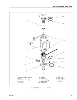
Страница 303: ...SECTION 4 BOOM PLATFORM 3121160 4 31 Figure 4 20 Rotator Assembly HELAC...
Страница 335: ...SECTION 4 BOOM PLATFORM 3121160 4 63 THIS SENSOR ON NON ADE MACHINES ONLY Figure 4 27 UMS Sensor Location...
Страница 336: ...SECTION 4 BOOM PLATFORM 4 64 3121160 Figure 4 28 UMS Module Location ADE MACHINES NON ADE MACHINES...
Страница 425: ...SECTION 5 BASIC HYDRAULIC INFORMATION AND SCHEMATICS 3121160 5 81 Figure 5 131 Variable Displacement Pump Rexroth...
Страница 443: ...SECTION 5 BASIC HYDRAULIC INFORMATION AND SCHEMATICS 3121160 5 99 Figure 5 146 Fault Logic Troubleshooting...
Страница 444: ...SECTION 5 BASIC HYDRAULIC INFORMATION AND SCHEMATICS 5 100 3121160 Figure 5 147 Fault Logic Troubleshooting...
Страница 445: ...SECTION 5 BASIC HYDRAULIC INFORMATION AND SCHEMATICS 3121160 5 101 Figure 5 148 Fault Logic Troubleshooting...
Страница 460: ...SECTION 5 BASIC HYDRAULIC INFORMATION AND SCHEMATICS 5 116 3121160 NOTES...
Страница 467: ...SECTION 6 JLG CONTROL SYSTEM 3121160 6 7 Figure 6 2 ADE Block Diagram...
Страница 471: ...SECTION 6 JLG CONTROL SYSTEM 3121160 6 11 Figure 6 6 Analyzer Flow Chart Prior to Version 5 X Software Sheet 4 of 4...
Страница 473: ...SECTION 6 JLG CONTROL SYSTEM 3121160 6 13 Figure 6 8 Analyzer Flow Chart Version 5 X Software Sheet 2 of 4...
Страница 534: ...SECTION 6 JLG CONTROL SYSTEM 6 74 3121160 NOTES...
Страница 545: ...SECTION 7 BASIC ELECTRICAL INFORMATION SCHEMATICS 3121160 7 11 Figure 7 15 Connector Installation...
Страница 580: ...SECTION 7 BASIC ELECTRICAL INFORMATION SCHEMATICS 7 46 3121160 NOTES...
Страница 581: ......

