


SECTION 3 - CHASSIS & TURNTABLE
3-198
3121160
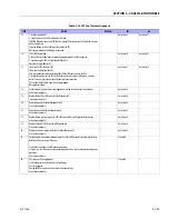
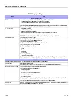
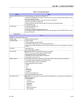
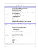
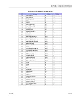
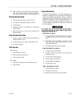
Table 3-14. LPF Fuel System Diagnosis
STEP
ACTION
VALUE(S)
YES
NO
1
Were you referred to this procedure by a DTC diagnostic chart?
- -
Go to Step 3
Go to Step 2
2
Perform the On Board Diagnostic (OBD) System Check.
Are any DTCs present in the ECM?
- -
Go to the
applicable DTC Table
Go to Step 3
3
Verify that the LPG fuel tank has a minimum of 1/4 tank of fuel, that the manual valve is open
and the tank quick connect is fully engaged
Does the vehicle have fuel?
- -
Go to Step 4
- -
4
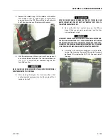
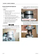
1. Connect a water column gauge or a manometer to the secondary test port of the low pressure
regulator (LPR).
2. Start the engine and allow it to reach operating temperature.
Does the engine start and run?
- -
Go to Step 5
Go to Step 8
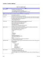
5
With the engine idling, observe the pressure reading for the LPR secondary pressure.
Does the fuel pressure fluctuate rhythmically OUTSIDE the specified range?
-1.0 in. to
-2.0 in. w.c
Go to Step 25
Go to Step 6
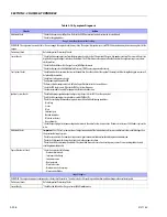
6
1. Disconnect the EPR electrical connectors. NOTE: This action will cause a DTC to be set by the
ECM
2. With the engine idling observe the pressure reading on the secondary test port.
Is the fuel pressure WITHIN the specified range?
-1.0 in. to
-2.0 in. w.c
Go to Fuel Control System
Diagnosis
Go to Step 7
7
1. Inspect the air intake stream between the mixer assembly and the throttle body for leaks.
2. Inspect the fuel hose connection between the LPR and mixer assembly for damage or leak-
age.
3. Inspect any vacuum hoses for leaks
Was a problem found and corrected?
- -
Go to Step 26
Go to Step 22
8
1. Connect a water column gauge or a manometer to the secondary test port of the low pressure
regulator (LPR).
2. Crank the engine and observe the pressure reading for the LPR secondary pressure.
Does the fuel pressure indicate a vacuum is present?
- -
Go to Step 12
Go to Step 9
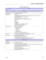
9
1. Remove Air induction hose to the mixer
2. Observe the air valve for movement while the engine is cranking. Note: Movement of the air
valve will be minimal at cranking speeds.
Does the air valve move when the engine is cranked?
- -
Go to Step 11
Go to Step 10
10
1. Inspect the air intake stream to the mixer assembly and the throttle body for vacuum leaks.
2. Inspect the vacuum hoses from the mixer for proper connection and condition.
Was a problem found and repaired?
- -
Go to Step 26
Go to Step 24
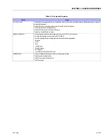
11
Inspect the fuel hose connection between the LPR and the mixer assembly for damage or leak-
age.
Was a problem found and repaired?
- -
Go to Step 26
Go to Step 12
12
1. Connect a 0-10 psi gauge to the primary test port of the low pressure regulator (LPR).
2. Crank the engine and observe the pressure reading for the LPR primary pressure.
Is the fuel pressure ABOVE the specified value?
1- 3 PSI
Go to Step 22
Go to Step 13
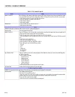
13
1. Turn OFF the ignition.
2. Disconnect the LPL connector.
3. Install a test light between the pins of the LPL connector.
4. Crank the engine. The test light should illuminate.
Does the test light illuminate?
- -
Go to Step 14
Go to Step 16
14
Using a DVOM, check the resistance of the low pressure lock-off (LPL).
Is the resistance within the specified range?
12
W
- 16
W
Go to Step 15
Go to Step 23
Содержание 740AJ
Страница 1: ...Service and Maintenance Manual Model 740AJ Prior to S N 0300185827 P N 3121160 October 24 2017 AS NZS...
Страница 2: ......
Страница 51: ...SECTION 2 GENERAL 3121160 2 11 Figure 2 2 Engine Operating Temperature Specifications Ford 4150548 E...
Страница 55: ...SECTION 3 CHASSIS TURNTABLE 3121160 3 3 This page left blank intentionally...
Страница 56: ...SECTION 3 CHASSIS TURNTABLE 3 4 3121160 1 Figure 3 2 Axle and Steering Installation Sheet 1 of 2 0258286 C...
Страница 100: ...SECTION 3 CHASSIS TURNTABLE 3 48 3121160 Figure 3 37 Swing Bearing Tolerance Boom Placement Sheet 1 of 2...
Страница 101: ...SECTION 3 CHASSIS TURNTABLE 3121160 3 49 Figure 3 38 Swing Bearing Tolerance Boom Placement Sheet 2 of 2...
Страница 116: ...SECTION 3 CHASSIS TURNTABLE 3 64 3121160 Figure 3 44 Swing Hub Prior to SN 0300074383...
Страница 124: ...SECTION 3 CHASSIS TURNTABLE 3 72 3121160 Figure 3 45 Swing Drive Hub Fairfield SN 0300074383 through 0300134352...
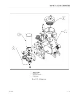
Страница 180: ...SECTION 3 CHASSIS TURNTABLE 3 128 3121160 1 Figure 3 66 Auxiliary Pump Location 1 AuxiliaryPump 2 HydraulicTank...
Страница 203: ...SECTION 3 CHASSIS TURNTABLE 3121160 3 151 Figure 3 77 EFI Component Location...
Страница 206: ...SECTION 3 CHASSIS TURNTABLE 3 154 3121160 Figure 3 78 ECM EPM Identification ECM EPM...
Страница 213: ...SECTION 3 CHASSIS TURNTABLE 3121160 3 161 Megajector Regulator LockoffSolenoid Figure 3 80 LPG System Components Mixer...
Страница 219: ...SECTION 3 CHASSIS TURNTABLE 3121160 3 167 Figure 3 81 Check Out and Initial Start Up Procedures...
Страница 224: ...SECTION 3 CHASSIS TURNTABLE 3 172 3121160 Figure 3 83 Deutz EMR 2 Troubleshooting Flow Chart...
Страница 225: ...SECTION 3 CHASSIS TURNTABLE 3121160 3 173 Figure 3 84 Deutz EMR 2 Vehicle Side Connection Diagram...
Страница 226: ...SECTION 3 CHASSIS TURNTABLE 3 174 3121160 Figure 3 85 Deutz EMR 2 Engine Side Connection Diagram Sheet 1 of 2...
Страница 227: ...SECTION 3 CHASSIS TURNTABLE 3121160 3 175 Figure 3 86 Deutz EMR 2 Engine Side Connection Diagram Sheet 2 of 2...
Страница 228: ...SECTION 3 CHASSIS TURNTABLE 3 176 3121160 Figure 3 87 EMR 2 Engine Plug Pin Identification...
Страница 229: ...SECTION 3 CHASSIS TURNTABLE 3121160 3 177 Figure 3 88 EMR 2 Vehicle Plug Pin Identification...
Страница 230: ...SECTION 3 CHASSIS TURNTABLE 3 178 3121160 Figure 3 89 EMR2 Fault Codes Sheet 1 of 5...
Страница 231: ...SECTION 3 CHASSIS TURNTABLE 3121160 3 179 Figure 3 90 EMR2 Fault Codes Sheet 2 of 5...
Страница 232: ...SECTION 3 CHASSIS TURNTABLE 3 180 3121160 Figure 3 91 EMR2 Fault Codes Sheet 3 of 5...
Страница 233: ...SECTION 3 CHASSIS TURNTABLE 3121160 3 181 Figure 3 92 EMR2 Fault Codes Sheet 4 of 5...
Страница 234: ...SECTION 3 CHASSIS TURNTABLE 3 182 3121160 Figure 3 93 EMR2 Fault Codes Sheet 5 of 5...
Страница 303: ...SECTION 4 BOOM PLATFORM 3121160 4 31 Figure 4 20 Rotator Assembly HELAC...
Страница 335: ...SECTION 4 BOOM PLATFORM 3121160 4 63 THIS SENSOR ON NON ADE MACHINES ONLY Figure 4 27 UMS Sensor Location...
Страница 336: ...SECTION 4 BOOM PLATFORM 4 64 3121160 Figure 4 28 UMS Module Location ADE MACHINES NON ADE MACHINES...
Страница 425: ...SECTION 5 BASIC HYDRAULIC INFORMATION AND SCHEMATICS 3121160 5 81 Figure 5 131 Variable Displacement Pump Rexroth...
Страница 443: ...SECTION 5 BASIC HYDRAULIC INFORMATION AND SCHEMATICS 3121160 5 99 Figure 5 146 Fault Logic Troubleshooting...
Страница 444: ...SECTION 5 BASIC HYDRAULIC INFORMATION AND SCHEMATICS 5 100 3121160 Figure 5 147 Fault Logic Troubleshooting...
Страница 445: ...SECTION 5 BASIC HYDRAULIC INFORMATION AND SCHEMATICS 3121160 5 101 Figure 5 148 Fault Logic Troubleshooting...
Страница 460: ...SECTION 5 BASIC HYDRAULIC INFORMATION AND SCHEMATICS 5 116 3121160 NOTES...
Страница 467: ...SECTION 6 JLG CONTROL SYSTEM 3121160 6 7 Figure 6 2 ADE Block Diagram...
Страница 471: ...SECTION 6 JLG CONTROL SYSTEM 3121160 6 11 Figure 6 6 Analyzer Flow Chart Prior to Version 5 X Software Sheet 4 of 4...
Страница 473: ...SECTION 6 JLG CONTROL SYSTEM 3121160 6 13 Figure 6 8 Analyzer Flow Chart Version 5 X Software Sheet 2 of 4...
Страница 534: ...SECTION 6 JLG CONTROL SYSTEM 6 74 3121160 NOTES...
Страница 545: ...SECTION 7 BASIC ELECTRICAL INFORMATION SCHEMATICS 3121160 7 11 Figure 7 15 Connector Installation...
Страница 580: ...SECTION 7 BASIC ELECTRICAL INFORMATION SCHEMATICS 7 46 3121160 NOTES...
Страница 581: ......


